Passive Components Blog
No Result
View All Result
  • Home
  • NewsFilter
    • All
    • Aerospace & Defence
    • Antenna
    • Applications
    • Automotive
    • Capacitors
    • Circuit Protection Devices
    • electro-mechanical news
    • Filters
    • Fuses
    • Inductors
    • Industrial
    • Integrated Passives
    • inter-connect news
    • Market & Supply Chain
    • Market Insights
    • Medical
    • Modelling and Simulation
    • New Materials & Supply
    • New Technologies
    • Non-linear Passives
    • Oscillators
    • Passive Sensors News
    • Resistors
    • RF & Microwave
    • Telecommunication
    • Weekly Digest

    Designing a 2 kW LLC Transformer with Integrated Resonant Inductor

    Middle East Conflict: The Potential Impact to Passive Components

    Inductor Technology Dossier

    Coilcraft Releases TLVR Inductors for High Density VRMs and PoL Converters

    Rutheniums Critical Role in Passive Component Supply Chains

    Bourns Expands its Modular Contacts for Power-Dense Systems

    Murata to Decouple China Rare Earth Supply in 3 Years

    Samtec AcceleRate Slim ARC6 Cable Assemblies with New Signaling Options

    Hirose Electric to Establish Automotive Connector Plant in India

    Trending Tags

    • Ripple Current
    • RF
    • Leakage Current
    • Tantalum vs Ceramic
    • Snubber
    • Low ESR
    • Feedthrough
    • Derating
    • Dielectric Constant
    • New Products
    • Market Reports
  • VideoFilter
    • All
    • Antenna videos
    • Capacitor videos
    • Circuit Protection Video
    • Filter videos
    • Fuse videos
    • Inductor videos
    • Inter-Connect Video
    • Non-linear passives videos
    • Oscillator videos
    • Passive sensors videos
    • Resistor videos

    Thermal Modeling of Magnetics

    Standard vs Planar LLC transformers Comparison for Battery Chargers

    How Modern Tools Model Magnetic Components for Power Electronics

    Advanced Loss Modeling for Planar Magnetics in the Frenetic Planar Tool

    2026 Power Magnetics Design Trends: Flyback, DAB and Planar

    Enabling Software‑Defined Vehicle Architectures: Automotive Ethernet and Zonal Smart Power

    Calculating Resistance Value of a Flyback RC Snubber 

    One‑Pulse Characterization of Nonlinear Power Inductors

    Thermistor Linearization Challenges

    Trending Tags

    • Capacitors explained
    • Inductors explained
    • Resistors explained
    • Filters explained
    • Application Video Guidelines
    • EMC
    • New Products
    • Ripple Current
    • Simulation
    • Tantalum vs Ceramic
  • Knowledge Blog
  • DossiersNew
  • Suppliers
    • Who is Who
  • PCNS
    • PCNS 2025
    • PCNS 2023
    • PCNS 2021
    • PCNS 2019
    • PCNS 2017
  • Events
No Result
View All Result
Passive Components Blog
No Result
View All Result

Resonators as Microwave Devices

15.10.2022
Reading Time: 5 mins read
A A

This blog post originated from Knowles Precision Devices, explores the basics of resonators as microwave devices and dive deeper into specifications for ceramic coaxial and dielectric resonators specifically.

Resonators are essential building blocks for bandpass filters as these components are designed to store frequency-dependent electric and magnetic energy.

RelatedPosts

Knowles Doubles Capacitance of its Class I Ceramic C0G Capacitors

Knowles Releases High Q Non-Magnetic X7R MLCCs for Medical Imaging

Knowles Unveils High-Performance Safety-Certified MLCC Capacitors

A simple resonator, such as an LC resonator, can store the frequency-dependent electric energy in the capacitance (C) and magnetic energy in the inductance (L).

Resonant frequency of a resonator occurs when the energy stored in the electric field is equal to the energy stored in the magnetic field. In this post, we’re going to look more closely at two different types of resonators used in filters – coaxial ceramic and dielectric.

Figure 1. How electrical and magnetic energy travel in a coaxial transmission line; credit Knowles Precision Devices

Coaxial Ceramic Resonators

If you’ve ever had cable television service, then you have used a ceramic coaxial transmission line. The transmission line is constructed using a ceramic rectangular prism with a coaxial hole running through the center.

More specifically, the ceramic coaxial resonator is a transmission line resonator that operates in transverse electromagnetic (TEM) mode. TEM mode has both E- and H-field components at right angles to the z-direction and no signals in the direction of propagation as shown in Figure 1.

Each coaxial resonator transmission line is cut to a specific length based on the wavelength of the frequency of interest. To make the lines shorter, ceramics with specific dielectric constants are used to shrink the wavelength to the frequency of interest.

The dielectric used, length of the line, and metallization will dictate the performance at the frequency of interest. Coaxial resonators can be supplied as λ/4 resonators with one end fully metallized (i.e., shorted) and the other end open, fully metallized on both ends, or as λ/2 resonators with both ends open as shown in Figure 2.

Figure 2. How a signal will be impacted depending on the type of ceramic coaxial resonator added.; credit Knowles Precision Devices

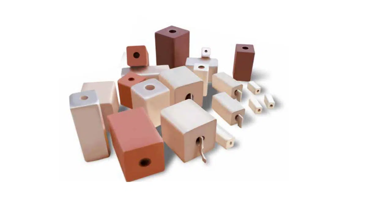
Knowles Precision Devices design high Q ceramic resonators made with class I dielectrics to operate in UHF, VHF, L, S, and C bands and in microwave frequency ranges, covering a total frequency range of 300 MHz to 5 GHz. A sampling of Knowles ceramic coaxial resonators is shown in Figure 3.

Some of the other key features of our range of ceramic coaxial resonators that are built at our facilities in the US include the following:

  • Standard frequency tolerances ranging from 0.1 percent to 1.0 precent, but custom tolerances are available
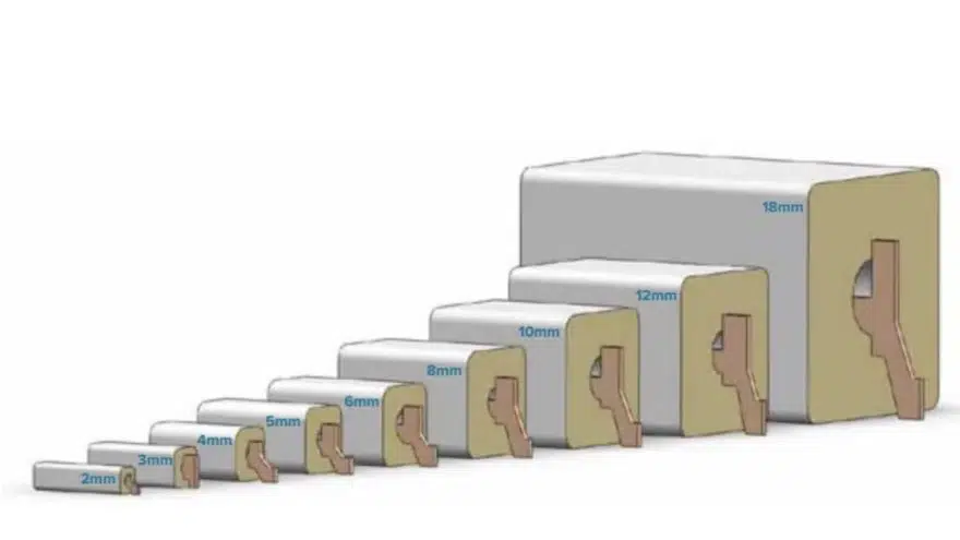
  • Resonator profiles ranging from 2mm to 18mm with custom profiles available (Figure 4)
  • Excellent temperature stability
  • A thick film silver coating for excellent Q and solderability
  • Superior silver adhesion with pull strengths greater than 20 lbs
Figure 3. A variety of Knowles tabbed and no-tab ceramic coaxial resonators.
Figure 4. The range of Knowles coaxial resonators.sizes

For surface mount devices (SMDs) tabs, tables, or slotted no-tab configurations are available, with our tabless version eliminating solder reflow issues and tab misalignments. Our resonators are pre-tuned to your specified frequency with a choice of tolerances and screened to ensure customer specifications are met. However, the self-resonant frequency (SRF) can be tuned by removing the silver metallization at either the open end or the shortened of the resonator to either increase or decrease the SRF.

For filtering applications specifically, our coaxial resonators made with modern, high-performance ceramic dielectric materials are an excellent option for bandpass, band stop, narrowband, delay, and EMI filters. You can also learn more about ceramic coaxial resonator technology in this related blog post.

Dielectric Resonators

Dielectric resonators are a kind of ceramic cavity resonator that work by confining frequencies inside the resonator material as a result of an abrupt change in permittivity at the surface, causing RF waves to bounce back and forth between the sides. The Knowles Precision Devices DLI brand includes a family of patented high-Q ceramic cavity resonators that offer an ideal solution for high-performance, low-cost microwave or mmWave oscillators with frequencies ranging from <1GHz to >67GHz (Figure 5).

Figure 5. Q vs frequency for various resonator types; credit: Knowles Precision Devices

As shown in this graph, these resonators can reach much higher frequencies than alternative technologies. These resonators are also fully shielded and designed on our temperature stable, high dielectric constant ceramics. Some of the key specifications that can be built into our range of DLI brand ceramic dielectric resonators include the following:

  • High Q, (up to 2000) over the 2GHz to 40+GHz range, offering 200 to 500 percent better Q over comparable technologies
  • Low loss, very low phase noise oscillators
  • Coupling capacitors can be integrated and tailored to the desired tuning range of the oscillator inside the package
  • Fully shielded – no large expensive housings or tuning screws
  • Frequency stability to < 3ppm/°C
  • Ready for automated assembly
  • Do not exhibit aging characteristics
  • Q leverage improves with increasing frequencies
  • Do not out-gas due to density of the material
  • High reliability thin film gold metallization is employed and frequency tolerances as low as 0.1% are attainable.

Dielectric resonator designs can be customized for either solder-surface mount or chip and wire applications as well.

Related

Source: Knowles Precision Devices

Recent Posts

Designing a 2 kW LLC Transformer with Integrated Resonant Inductor

20.3.2026
6
Schematic illustration of the electric double layer of porous carbon electrodes at elevated potentials in a a conventional electrolyte and b a weakly solvating electrolyte; source: authors

Researchers Presented Lignin-based Electrolyte for 4V Supercapacitors with Low Self‑Discharge

19.3.2026
7

Thermal Modeling of Magnetics

16.3.2026
19

Panasonic Releases Transparent EMI Shielding Film for Displays

16.3.2026
16

Standard vs Planar LLC transformers Comparison for Battery Chargers

13.3.2026
28

How Modern Tools Model Magnetic Components for Power Electronics

5.3.2026
56

Advanced Loss Modeling for Planar Magnetics in the Frenetic Planar Tool

4.3.2026
53

Mastering Galvanic Isolation in Power Electronics: Methods, Standards, and Implementation

2.3.2026
91

Earthing Systems and IEC Classification Explained

26.2.2026
182

Upcoming Events

Mar 21
All day

PSMA Capacitor Workshop 2026

Mar 24
9:00 - 10:00 CET

Power protection in the digital age – eFuse and hot-swap strategies for modern data center design

Apr 21
16:00 - 17:00 CEST

Heatsink Solutions: Thermal Management in electronic devices

View Calendar

Popular Posts

  • Buck Converter Design and Calculation

    0 shares
    Share 0 Tweet 0
  • Boost Converter Design and Calculation

    0 shares
    Share 0 Tweet 0
  • Flyback Converter Design and Calculation

    0 shares
    Share 0 Tweet 0
  • LLC Resonant Converter Design and Calculation

    0 shares
    Share 0 Tweet 0
  • MLCC Manufacturers Consider Price Increase as AI Demand Outpaces Supply

    0 shares
    Share 0 Tweet 0
  • MLCC and Ceramic Capacitors

    0 shares
    Share 0 Tweet 0
  • Dual Active Bridge (DAB) Topology

    0 shares
    Share 0 Tweet 0
  • Ripple Current and its Effects on the Performance of Capacitors

    3 shares
    Share 3 Tweet 0
  • MLCC Case Sizes Standards Explained

    0 shares
    Share 0 Tweet 0
  • What is a Dielectric Constant and DF of Plastic Materials?

    4 shares
    Share 4 Tweet 0

Newsletter Subscription


Passive Components Blog

© EPCI - Leading Passive Components Educational and Information Site

  • Home
  • Privacy Policy
  • EPCI Membership & Advertisement
  • About

No Result
View All Result
  • Home
  • Knowledge Blog
  • PCNS

© EPCI - Leading Passive Components Educational and Information Site

This website uses cookies. By continuing to use this website you are giving consent to cookies being used. Visit our Privacy and Cookie Policy.
Go to mobile version