Passive Components Blog
No Result
View All Result
  • Home
  • NewsFilter
    • All
    • Aerospace & Defence
    • Antenna
    • Applications
    • Automotive
    • Capacitors
    • Circuit Protection Devices
    • electro-mechanical news
    • Filters
    • Fuses
    • Inductors
    • Industrial
    • Integrated Passives
    • inter-connect news
    • Market & Supply Chain
    • Market Insights
    • Medical
    • Modelling and Simulation
    • New Materials & Supply
    • New Technologies
    • Non-linear Passives
    • Oscillators
    • Passive Sensors News
    • Resistors
    • RF & Microwave
    • Telecommunication
    • Weekly Digest

    YAGEO Unveils Compact 3.6kW LLC Transformer for OBC EV Charging

    Over-Voltage Protection Clippers, Clampers, Snubbers, DC Restorers

    KYOCERA Releases Shielded Board-to-Board Connectors for Reliable EMI Protection

    Wk 41 Electronics Supply Chain Digest

    Samtec Expands Connector Severe Environment Testing Offering

    Silicon Capacitors Market: Shaping the Foundation for Next-Gen Miniaturization Electronics

    YAGEO Releases Compact Coupled Inductors for High-Density VR Designs

    Enhancing Energy Density in Nanocomposite Dielectric Capacitors

    Advances in the Environmental Performance of Polymer Capacitors

    Trending Tags

    • Ripple Current
    • RF
    • Leakage Current
    • Tantalum vs Ceramic
    • Snubber
    • Low ESR
    • Feedthrough
    • Derating
    • Dielectric Constant
    • New Products
    • Market Reports
  • VideoFilter
    • All
    • Antenna videos
    • Capacitor videos
    • Circuit Protection Video
    • Filter videos
    • Fuse videos
    • Inductor videos
    • Inter-Connect Video
    • Non-linear passives videos
    • Oscillator videos
    • Passive sensors videos
    • Resistor videos

    Connector PCB Design Challenges

    Efficient Power Converters: Duty Cycle vs Conduction Losses

    Ripple Steering in Coupled Inductors: SEPIC Case

    SEPIC Converter with Coupled and Uncoupled Inductors

    Coupled Inductors in SEPIC versus Flyback Converters

    Non-Linear MLCC Class II Capacitor Measurements Challenges

    Percolation Phenomenon and Reliability of Molded Power Inductors in DC/DC converters

    Root Causes and Effects of DC Bias and AC in Ceramic Capacitors

    How to Calculate the Output Capacitor for a Switching Power Supply

    Trending Tags

    • Capacitors explained
    • Inductors explained
    • Resistors explained
    • Filters explained
    • Application Video Guidelines
    • EMC
    • New Products
    • Ripple Current
    • Simulation
    • Tantalum vs Ceramic
  • Knowledge Blog
  • Suppliers
    • Who is Who
  • Events
No Result
View All Result
Passive Components Blog
No Result
View All Result

Ripple Steering in Coupled Inductors: SEPIC Case

27.8.2025
Reading Time: 3 mins read
A A

prof. Sam Ben-Yaakov in this video explains ripple steering in coupled inductors and provide case study on SEPIC converters.

This presentation explores the concept of ripple steering within coupled inductors, with a specific focus on SEPIC (Single-Ended Primary Inductor Converter) configurations.

RelatedPosts

Over-Voltage Protection Clippers, Clampers, Snubbers, DC Restorers

Efficient Power Converters: Duty Cycle vs Conduction Losses

Coupled Inductors in SEPIC versus Flyback Converters

1. Introduction:

Ripple steering is a technique used in power electronics to manage and redistribute current ripple between inductors in a coupled system. This presentation revisits the principles of ripple steering, applying them to SEPIC converters, commonly used for their versatile voltage conversion capabilities.

2. SEPIC Converter Configuration:

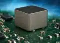
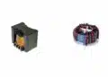
The SEPIC converter analyzed includes a transistor switch and two coupled inductors with nominal inductances of 50 µH. The inductors exhibit slight variations due to coupling coefficients, which is central to ripple steering mechanisms. The SEPIC converter’s advantage lies in its ability to maintain a transfer ratio both below and above unity, akin to the buck-boost converter.

3. Theoretical Background:

Coupled inductors in switch-mode power supplies (SMPS) require voltage symmetry across the inductors during on/off states to prevent short circuits. Any significant voltage mismatch transforms the coupled inductors into a transformer, potentially causing excessive currents. Minor deviations are mitigated by leakage inductance. The nominal design typically assumes equal inductances and a 1:1 turns ratio.

Ripple steering aims to shift current ripple from one inductor to another, thereby reducing ripple in targeted areas. In SEPIC converters, minimizing input inductor ripple is critical for Electromagnetic Interference (EMI) considerations.

4. Methodology:

Ripple steering is influenced by two main factors:

  • Coupling Coefficient (K): Reducing K increases leakage inductance, affecting ripple distribution.
  • Turns Ratio (KK): Altering KK modifies the current-sharing properties between inductors based on the square root relationship to inductance.

Simulations were conducted using LTspice to analyze ripple behavior under varying K and KK values. The study monitored gate signals and ripple waveforms across inductors L1 and L2.

5. Results:

  • Baseline Case (K=1, KK=1): Ripple currents in L1 and L2 were symmetrical, with peak-to-peak values around 2 A.
  • Modified Coupling (K=0.95, KK=0.9): A reduction in L1 ripple was observed, while L2 ripple remained relatively unchanged, transitioning to a triangular waveform due to higher leakage.
  • Ripple Steering Impact: By sweeping KK between 0.8 and 1.2, significant shifts in ripple distribution were noted. For example, reducing KK to 0.9 decreased L1 ripple considerably, demonstrating up to a 4.5-fold reduction compared to the balanced case.

6. Discussion:

The simulation results confirm that ripple can be effectively steered between inductors by adjusting K and KK. While the phenomenon lacks a comprehensive analytical model, empirical data underscores its potential for practical EMI reduction in SEPIC converters.

7. Conclusion:

Ripple steering in coupled inductors presents a valuable approach for optimizing current ripple in SEPIC converters. The findings highlight the method’s applicability, particularly in scenarios demanding stringent EMI performance. Future work may focus on developing analytical frameworks to predict ripple behavior more accurately.

References:

S. Cuk, “Integrated Magnetics versus Conventional Power Filtering,” INTELEC ’87 – The Ninth International Telecommunications Energy Conference, Stockholm, Sweden, 1987, pp. 61-72, doi: 10.1109/INTLEC.1987.4794530.

Relevant posts:

  • Coupled Inductors in SEPIC versus Flyback Converters

SEPIC Converter Design and Calculation

Related

Source: Sam Ben-Yaakov

Recent Posts

YAGEO Unveils Compact 3.6kW LLC Transformer for OBC EV Charging

13.10.2025
49

Over-Voltage Protection Clippers, Clampers, Snubbers, DC Restorers

13.10.2025
10

YAGEO Releases Compact Coupled Inductors for High-Density VR Designs

9.10.2025
17

Vishay Expanded Inductor Portfolio With More Than 2000 Stock Items 

8.10.2025
14

Connector PCB Design Challenges

3.10.2025
37

Experimental Evaluation of Wear Failures in SMD Inductors

1.10.2025
42

Resonant Capacitors in High-Power Resonant Circuits

1.10.2025
46

Efficient Power Converters: Duty Cycle vs Conduction Losses

29.9.2025
36

Passive Components J-STD-075 Process Sensitivity Level Classification And Labeling

25.9.2025
61

Bourns Releases Semi-Shielded Power Inductor with Polarity Control

25.9.2025
14

Upcoming Events

Oct 14
16:00 - 17:00 CEST

Smart Sensors, Smarter AI: Building Reliable Edge Systems

Oct 17
12:00 - 14:00 EDT

External Visual Inspection per MIL-STD-883 TM 2009

Oct 20
October 20 - October 23

Digital WE Days 2025 – Virtual Conference

View Calendar

Popular Posts

  • Buck Converter Design and Calculation

    0 shares
    Share 0 Tweet 0
  • Boost Converter Design and Calculation

    0 shares
    Share 0 Tweet 0
  • Flyback Converter Design and Calculation

    0 shares
    Share 0 Tweet 0
  • LLC Resonant Converter Design and Calculation

    0 shares
    Share 0 Tweet 0
  • What is a Dielectric Constant and DF of Plastic Materials?

    4 shares
    Share 4 Tweet 0
  • Ripple Current and its Effects on the Performance of Capacitors

    3 shares
    Share 3 Tweet 0
  • SEPIC Converter Design and Calculation

    0 shares
    Share 0 Tweet 0
  • Dual Active Bridge (DAB) Topology Explained

    0 shares
    Share 0 Tweet 0
  • MLCC and Ceramic Capacitors

    0 shares
    Share 0 Tweet 0
  • Flying Capacitors Explained

    0 shares
    Share 0 Tweet 0

Newsletter Subscription


Passive Components Blog

© EPCI - Leading Passive Components Educational and Information Site

  • Home
  • Privacy Policy
  • EPCI Membership & Advertisement
  • About

No Result
View All Result
  • Home
  • Knowledge Blog
  • Premium Suppliers

© EPCI - Leading Passive Components Educational and Information Site

This website uses cookies. By continuing to use this website you are giving consent to cookies being used. Visit our Privacy and Cookie Policy.
Go to mobile version