











Passive Components Blog
No Result
View All Result
  • Home
  • NewsFilter
    • All
    • Aerospace & Defence
    • Antenna
    • Applications
    • Automotive
    • Capacitors
    • Circuit Protection Devices
    • electro-mechanical news
    • Filters
    • Fuses
    • Inductors
    • Industrial
    • Integrated Passives
    • inter-connect news
    • Market & Supply Chain
    • Market Insights
    • Medical
    • Modelling and Simulation
    • New Materials & Supply
    • New Technologies
    • Non-linear Passives
    • Oscillators
    • Passive Sensors News
    • Resistors
    • RF & Microwave
    • Telecommunication
    • Weekly Digest

    Bourns Introduces Automotive Shielded Power Inductors for Compact DC‑DC Converters

    EMC Design Fundamentals: Safe Use of Varistors and Common Mode Chokes in Mains and Data-Line Filters

    Murata Unveils Lead Disc Ceramic Capacitors for Automotive Safety and EMI Suppression

    SCHURTER Releases Intelligent Three‑Terminal Fuses for Safer Li‑ion Battery Systems

    Can Copper Conductive Inks Displace Silver in Hybrid Electronics?

    Square-Wave Harmonics and RMS Currents in Power Converters

    LeanBOM: Practical Cross‑Technology Capacitor Search by Real Working Conditions

    In the Age of AI, Every Watt Counts: Implications for Components

    Stackpole Extends Resistance Range of 2512 High‑Power Current Sense Resistors

    Trending Tags

    • Ripple Current
    • RF
    • Leakage Current
    • Tantalum vs Ceramic
    • Snubber
    • Low ESR
    • Feedthrough
    • Derating
    • Dielectric Constant
    • New Products
    • Market Reports
  • VideoFilter
    • All
    • Antenna videos
    • Capacitor videos
    • Circuit Protection Video
    • Filter videos
    • Fuse videos
    • Inductor videos
    • Inter-Connect Video
    • Non-linear passives videos
    • Oscillator videos
    • Passive sensors videos
    • Resistor videos

    EMC Design Fundamentals: Safe Use of Varistors and Common Mode Chokes in Mains and Data-Line Filters

    Ferrite versus Nanocrystalline Power Inductor Cores: Turns, Gap and Size

    KYOCERA AVX Presents Antenna Integrator Studio Tutorial for Antenna Placement and RF Design

    Power Design Simulation Tools for Faster Inductor Selection and Loss Optimization

    EMC‑Compliant PCB and Connector Design Guidelines

    Why Isolated DC/DC Power Supplies Fail Late, Würth Elektronik Podcast

    Designing 800 V DC EMC Filters: Calculation, Simulation and Measurement

    Current Sense Transformer Datasheet and Design‑in Guide

    Designing a USB Type‑C Flyback Planar Transformer with Frenetic’s Planar Tool

    Trending Tags

    • Capacitors explained
    • Inductors explained
    • Resistors explained
    • Filters explained
    • Application Video Guidelines
    • EMC
    • New Products
    • Ripple Current
    • Simulation
    • Tantalum vs Ceramic
  • Knowledge Blog
  • Dossiers
    • AI Hardware Dossier
    • Power Converter Dossier
    • Automotive Dossier
    • Capacitor Dossier
    • Resistor Dossier
    • Inductor Dossier
    • Circuit Protection Dossier
  • Suppliers
    • Who is Who
  • PCNS
    • PCNS 2025
    • PCNS 2023
    • PCNS 2021
    • PCNS 2019
    • PCNS 2017
  • Events
  • Home
  • NewsFilter
    • All
    • Aerospace & Defence
    • Antenna
    • Applications
    • Automotive
    • Capacitors
    • Circuit Protection Devices
    • electro-mechanical news
    • Filters
    • Fuses
    • Inductors
    • Industrial
    • Integrated Passives
    • inter-connect news
    • Market & Supply Chain
    • Market Insights
    • Medical
    • Modelling and Simulation
    • New Materials & Supply
    • New Technologies
    • Non-linear Passives
    • Oscillators
    • Passive Sensors News
    • Resistors
    • RF & Microwave
    • Telecommunication
    • Weekly Digest

    Bourns Introduces Automotive Shielded Power Inductors for Compact DC‑DC Converters

    EMC Design Fundamentals: Safe Use of Varistors and Common Mode Chokes in Mains and Data-Line Filters

    Murata Unveils Lead Disc Ceramic Capacitors for Automotive Safety and EMI Suppression

    SCHURTER Releases Intelligent Three‑Terminal Fuses for Safer Li‑ion Battery Systems

    Can Copper Conductive Inks Displace Silver in Hybrid Electronics?

    Square-Wave Harmonics and RMS Currents in Power Converters

    LeanBOM: Practical Cross‑Technology Capacitor Search by Real Working Conditions

    In the Age of AI, Every Watt Counts: Implications for Components

    Stackpole Extends Resistance Range of 2512 High‑Power Current Sense Resistors

    Trending Tags

    • Ripple Current
    • RF
    • Leakage Current
    • Tantalum vs Ceramic
    • Snubber
    • Low ESR
    • Feedthrough
    • Derating
    • Dielectric Constant
    • New Products
    • Market Reports
  • VideoFilter
    • All
    • Antenna videos
    • Capacitor videos
    • Circuit Protection Video
    • Filter videos
    • Fuse videos
    • Inductor videos
    • Inter-Connect Video
    • Non-linear passives videos
    • Oscillator videos
    • Passive sensors videos
    • Resistor videos

    EMC Design Fundamentals: Safe Use of Varistors and Common Mode Chokes in Mains and Data-Line Filters

    Ferrite versus Nanocrystalline Power Inductor Cores: Turns, Gap and Size

    KYOCERA AVX Presents Antenna Integrator Studio Tutorial for Antenna Placement and RF Design

    Power Design Simulation Tools for Faster Inductor Selection and Loss Optimization

    EMC‑Compliant PCB and Connector Design Guidelines

    Why Isolated DC/DC Power Supplies Fail Late, Würth Elektronik Podcast

    Designing 800 V DC EMC Filters: Calculation, Simulation and Measurement

    Current Sense Transformer Datasheet and Design‑in Guide

    Designing a USB Type‑C Flyback Planar Transformer with Frenetic’s Planar Tool

    Trending Tags

    • Capacitors explained
    • Inductors explained
    • Resistors explained
    • Filters explained
    • Application Video Guidelines
    • EMC
    • New Products
    • Ripple Current
    • Simulation
    • Tantalum vs Ceramic
  • Knowledge Blog
  • Dossiers
    • AI Hardware Dossier
    • Power Converter Dossier
    • Automotive Dossier
    • Capacitor Dossier
    • Resistor Dossier
    • Inductor Dossier
    • Circuit Protection Dossier
  • Suppliers
    • Who is Who
  • PCNS
    • PCNS 2025
    • PCNS 2023
    • PCNS 2021
    • PCNS 2019
    • PCNS 2017
  • Events
No Result
View All Result
Passive Components Blog
No Result
View All Result

Coilcraft Releases Automotive Common Mode Chokes

19.2.2026
Reading Time: 7 mins read
A A

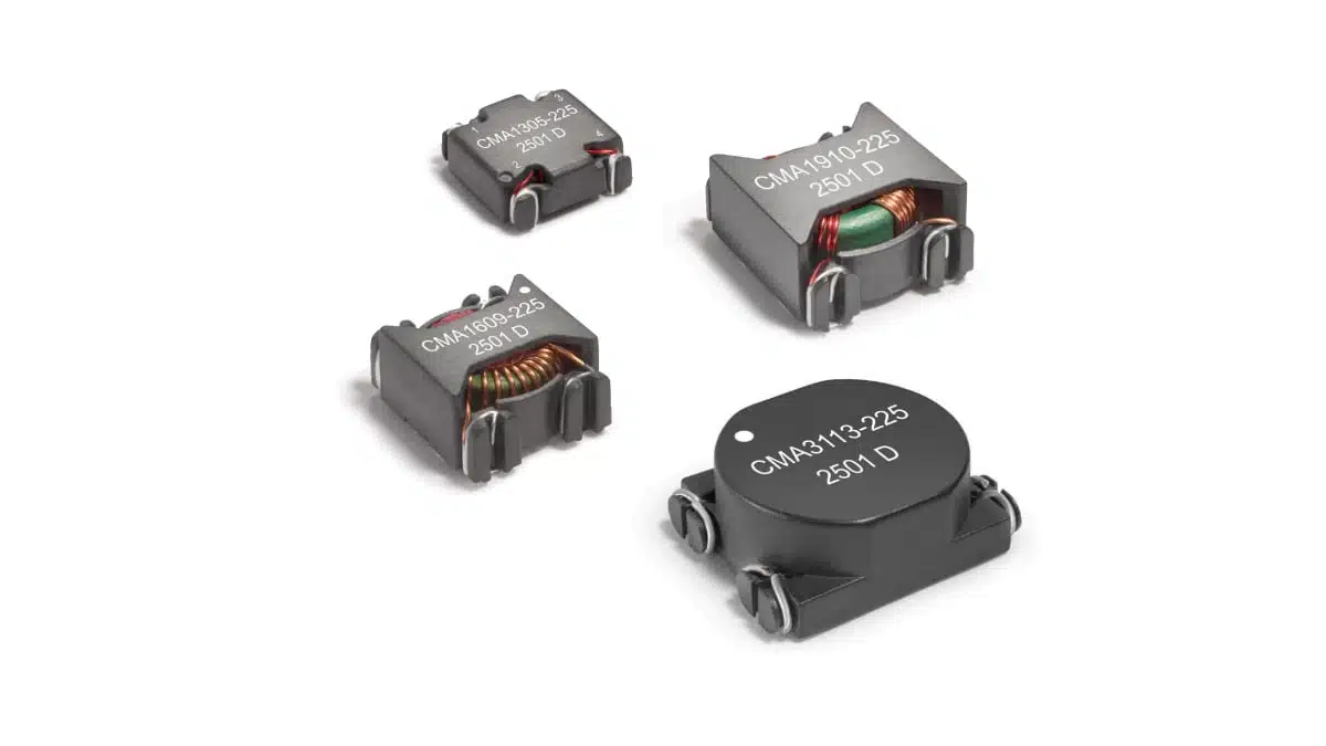
Coilcraft’s CMA family is a series of automotive‑qualified surface‑mount common mode chokes designed for EMI suppression in high‑current power line applications.

They target compact inverters, motor drives, onboard chargers, telecom and industrial supplies where high isolation and robust thermal performance are critical.

RelatedPosts

Coilcraft Releases High-Current Ferrite Beads for CISPR 25 EMC compliance

Coilcraft Releases 0402 Ferrite-Core Wirewound Chip Inductors for RF and EMI Control

Coilcraft Introduces SMT Current Sense Transformers for High‑Performance Power Electronics

Key features and benefits

The CMA series is positioned as a high‑isolation, AEC‑Q200 qualified common mode choke family for power electronics where conducted EMI limits are tightening and available PCB area is at a premium.

Key characteristics include:

  • Automotive qualified (AEC‑Q200) surface‑mount toroidal construction.
  • High frequency common mode noise suppression up to 100 MHz.
  • Isolation (hipot) rating of 1500 Vrms between windings.
  • Excellent current ratings up to 8.2 A rms depending on case size and inductance value.
  • Broad range of common mode impedances and inductance values per winding.
  • Ferrite core material for high permeability and stable high‑frequency performance.
  • Moisture Sensitivity Level 1, suitable for standard SMT processes and washing.

For design engineers, the combination of high isolation, high common‑mode impedance and SMT packaging simplifies meeting safety and EMC requirements without resorting to bulky through‑hole magnetics.

Typical applications

The CMA series is dedicated for automotive and general power line filtering tasks where common‑mode noise must be attenuated on AC or DC supply rails.

Typical use cases include:

  • Automotive inverters and traction motor drives on HV or LV bus lines.
  • Onboard chargers in EV/HEV platforms, particularly on AC input and DC output lines.
  • Automotive 12 V and 48 V power distribution modules and auxiliary converters.
  • Telecom and datacom power systems requiring 1500 Vrms isolation.
  • Industrial power supplies and motor drives with stringent conducted EMI limits.
  • Consumer electronics power adapters where high isolation and compact toroidal SMT parts are desired.

In these applications, the choke is typically placed in series with the supply and return conductors (two lines) to block common‑mode noise currents while allowing the desired DC or low‑frequency current to pass with minimal loss.

Technical highlights

The CMA family currently comprises four case sizes (CMA1305, CMA1609, CMA1910, CMA3113) and three nominal inductance ranges per size, giving a matrix of 12 part numbers.

Electrical parameters (overview)

  • Inductance per winding (typical family values): approximately 0.47 mH, 1.0 mH and 2.2 mH options per case size, with minimum inductance specified in the table according to the manufacturer datasheet.
  • Common mode peak impedance: from about 1.2 kΩ to 8.5 kΩ at test frequencies between 0.9 MHz and 2.6 MHz depending on part number.
  • Current ratings (Irms):
    • CMA1305 series: up to about 2.5 A.
    • CMA1609 series: up to about 4.3 A.
    • CMA1910 series: up to about 6.0 A.
    • CMA3113 series: up to about 8.2 A.
  • DCR per winding: from single‑digit milliohm values in larger sizes (e.g. 8.7 mΩ) up to a few hundred milliohms (e.g. 208 mΩ) in the smallest, highest‑inductance variants.
  • Isolation voltage (winding to winding): 1500 Vrms for all listed CMA part numbers, measured for 1 minute.

Irms is defined as the current flowing through both windings in series that causes a 40 °C temperature rise, and is provided for reference rather than as an absolute maximum rating. In practice, designers should derate according to ambient conditions, cooling and system‑level thermal design.

Design‑in notes for engineers

From an EMC and power design perspective, the CMA series is a general‑purpose high‑isolation common mode choke family covering a useful span of inductances and current ratings for automotive and industrial power lines.

Practical selection guidelines:

  • Choose the case size first based on required Irms and acceptable DCR:
    • CMA1305 for low‑to‑moderate currents where board space is tight and losses from higher DCR are acceptable.
    • CMA1609 and CMA1910 as mid‑range options balancing footprint and current capability.
    • CMA3113 for highest current demands up to 8.2 A with very low DCR and correspondingly larger footprint.
  • Select inductance and common‑mode impedance according to desired attenuation profile:
    • Higher inductance (e.g. “225” variants) gives higher impedance at low frequencies but typically higher DCR and lower Irms.
    • Lower inductance (e.g. “474” variants) suits higher‑current rails and may be preferred where losses must be minimized and EMI issues are more high‑frequency in nature.
  • Consider the noise spectrum:
    • Manufacturer tables specify common‑mode peak impedance at a given MHz frequency; use these values and the supplied S‑parameter data to model performance against your measured noise spectrum.
  • Verify isolation requirements:
    • The 1500 Vrms isolation rating is suitable for many automotive, telecom and industrial applications, but designers must still check system‑level safety standards (e.g. reinforced vs basic insulation, creepage/clearance on the PCB) and use the manufacturer’s dimensional drawings.
  • Thermal management:
    • The Irms values are referenced to a 40 °C temperature rise; in hot environments (e.g. 85–105 °C ambient) some derating is advisable to stay below the 155 °C maximum part temperature.
    • Where thermal margin is limited, prefer larger packages operating below their rated Irms to reduce core and copper losses.
  • Layout considerations:
    • Place the common mode choke close to the input or noisy source to minimize loop area and parasitic coupling.
    • Keep the two lines of each pair routed together into and out of the component to preserve common‑mode coupling and avoid unintended differential‑mode filtering effects.

Coilcraft provides a dedicated Common Mode Choke Finder and Analyzer tool as well as S‑parameter files for the CMA family, which can greatly simplify optimization of EMI filter performance during early design and troubleshooting.

Source

This article is based on publicly available technical information and datasheets from Coilcraft for the CMA automotive qualified common mode choke family, adapted and commented for design‑in and purchasing decisions.


References

  1. Coilcraft CMA Family – Automotive SMT Common Mode Chokes
  2. Coilcraft CMA Series Datasheet (PDF)
  3. Coilcraft Common Mode Choke Finder and Analyzer

Related

Recent Posts

Bourns Introduces Automotive Shielded Power Inductors for Compact DC‑DC Converters

16.7.2026
4

EMC Design Fundamentals: Safe Use of Varistors and Common Mode Chokes in Mains and Data-Line Filters

16.7.2026
28

Murata Unveils Lead Disc Ceramic Capacitors for Automotive Safety and EMI Suppression

15.7.2026
21

SCHURTER Releases Intelligent Three‑Terminal Fuses for Safer Li‑ion Battery Systems

14.7.2026
29

Square-Wave Harmonics and RMS Currents in Power Converters

14.7.2026
24

In the Age of AI, Every Watt Counts: Implications for Components

13.7.2026
43

Stackpole Extends Resistance Range of 2512 High‑Power Current Sense Resistors

13.7.2026
18

Littelfuse Announced TVS Diodes for 48 V Automotive Systems

10.7.2026
28

RF Filters and Passive Components Enabling the 7 Missile RF Subsystems

9.7.2026
49

Upcoming Events

Jul 21
16:00 - 17:00 CEST

Safety by design: X and Y Interference suppression capacitors for power line filters

Jul 28
8:00 - 11:00 CEST

Post Procurement Testing of EEE Components for LEO Space Applications

Jul 29
17:30 - 18:30 CEST

To Ferrite or to Nanocrystalline in Transformer Design

View Calendar

Popular Posts

  • Boost Converter Design and Calculation

    0 shares
    Share 0 Tweet 0
  • Buck Converter Design and Calculation

    0 shares
    Share 0 Tweet 0
  • Flyback Converter Design and Calculation

    0 shares
    Share 0 Tweet 0
  • YAGEO Announces July 2026 Capacitor Price Increase

    0 shares
    Share 0 Tweet 0
  • LLC Resonant Converter Design and Calculation

    0 shares
    Share 0 Tweet 0
  • MLCC and Ceramic Capacitors

    0 shares
    Share 0 Tweet 0
  • Earthing Systems and IEC Classification Explained

    0 shares
    Share 0 Tweet 0
  • Nvidia Vera Rubin: Why One AI Rack Needs So Many More MLCC Capacitors

    0 shares
    Share 0 Tweet 0
  • MLCCs in the Age of AI: Q2 2026 Market Tightness

    0 shares
    Share 0 Tweet 0
  • Dual Active Bridge (DAB) Topology

    0 shares
    Share 0 Tweet 0

Newsletter Subscription


Passive Components Blog

© EPCI - Leading Passive Components Educational and Information Site

  • Home
  • Privacy Policy
  • EPCI Membership & Advertisement
  • About

No Result
View All Result
  • Home
  • Knowledge Blog
  • Dossiers
  • PCNS

© EPCI - Leading Passive Components Educational and Information Site

This website uses cookies. By continuing to use this website you are giving consent to cookies being used. Visit our Privacy and Cookie Policy.
Go to mobile version










