


Designing medical implantable devices for high reliability is crucial for a variety of reasons. To ensure that used components are manufactured to meet medical implantable application standards, proper screening and high reliability design is required. This paper elaborates on requirements for MLCC ceramic capacitor to meet such medical standards.
The paper was written by Victor Lu and presented by Samuel Dowrick, Knowles Precision Devices, UK at the 4th PCNS 10-14th September 2023, Sønderborg, Denmark as paper No. 3.2.
ABSTRACT
Since patient safety is paramount, any precautions to reduce the possibility of potentially life-threatening malfunctions, recalls, and replacement surgeries are necessary. And, beyond preventing patient safety issues, there may also be severe economic and legal implications for device manufacturers if an implantable device fails. To ensure that these components are manufactured to meet medical implantable application standards, proper screening and high reliability design is required. Both aspects are critical when choosing components implemented into the human body.
INTRODUCTION
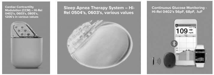
A medical implantable device is any piece of equipment that is surgically placed inside the human body to help a person rebuild or rehabilitate a bodily function, obtain better quality of life, or increase longevity of the body. Several common examples of medical implantable devices are shown in Figure 1.
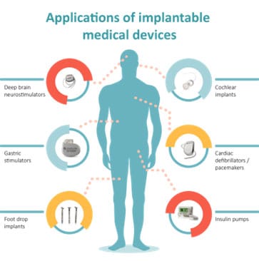
Given the life-critical functions performed by many of these devices, and the fact that an invasive procedure is required to implant medical equipment properly in the human body, it is imperative that all medical devices be designed to function reliably throughout their entire lifetime. But this can be challenging as medical implantable devices are made up of many individual parts.
For many medical implantable devices, a variety of electronic components such as capacitors, resistors, batteries, inductors, and transistors are required. The manufacturers of these components are faced with particularly unique challenges as they are continually tasked with responding to the demand for new products that are increasingly smaller while still meeting the high-reliability expectations for these life critical applications.
This paper dives more into the challenges associated with ensuring electronic component reliability for medical implantable devices by looking specifically at the role multilayer ceramic capacitors (MLCCs) serve in medical implantable. It also covers how Knowles Precision Devices designs, tests, and continues to innovate on our MLCCs, making our MLCCs a leading choice for meeting all the key requirements of the medical device industry, including high reliability.
MLCC DESIGN CONSIDERATIONS FOR MEDICAL IMPLANTABLE DEVICES
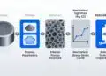
To better understand how MLCCs function in an implantable devices’ electronic circuit, let’s first review the basics of how MLCCs are built. In general, capacitors are passive electronic components that store an electric charge in an electric field that can be discharged in an instant, which is unlike a battery since batteries store energy and gradually release it. MLCCs are a type of capacitor constructed of layers of dielectric, or a ceramic material that is paraelectric or ferroelectric, and electrodes joined by a termination material. The electrodes need to be made of a good conduction material such as silver, copper, nickel, or palladium, while the layers of ceramics are built up using a wet or dry screen-printing process.
There is a lot for medical device designers to think about when it comes to MLCC selection for medical implantable devices. First, since market demands are driving device designers to continuously miniaturize implantable devices, component size is critical and compact case sizes from 0201-2225 are generally required for MLCCs. Device designers also need to be sure the MLCCs can handle the voltage and capacitance demands of the device, which can mean up to 100 V and up to 22 uF.
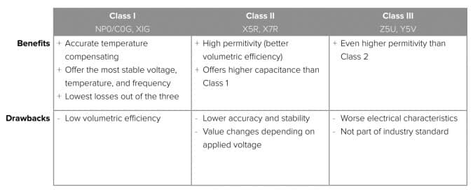
Dielectric selection is also critical for medical implantable device MLCCs since the dielectric must be able to manage the operating temperature and temperature coefficients of the device. The graph in Figure 2. shows how capacitance changes as temperature increases for some of the dielectrics presented in Table 1.
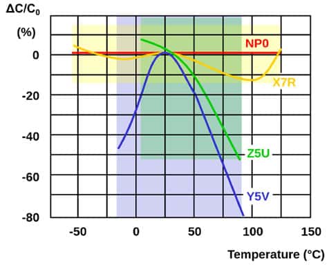
As shown in the graph, capacitance decreases substantially as temperature increases for the Class III dielectric Y5V compared to the other two classes, which means Class III is not a good option for high reliability for medical implantable devices. The Class I dielectric NP0 is the most stable of all these options as any change in capacitance over the operating temperature range is negligible – which supports high reliability. But as shown in Table 1, the main issue with Class I dielectrics generally is that volumetric efficiency is low, making it difficult to achieve high capacitance.
The Class II dielectric X7R offers much better volumetric efficiency, meaning higher capacitance. However, it is not as stable because capacitance will vary (usually decrease) when there is an increase in temperature and DC voltage applied, while Class I dielectrics are not affected by either of these properties. Additionally, another key design difference related to the dielectrics used for high-reliability (Hi-Rel) MLCCs versus standard MLCCs is the thickness of the dielectric.
Increasing the thickness of the dielectric layers offers a more robust design, which provides MLCCs with the adequate insulation strength to withstand Hi-Rel testing such as voltage conditioning and life testing. When working with thicker dielectrics, certain aspects of the MLCC must be taken into consideration such as the total height of the MLCC, the density of the dielectric, and the potential decrease in capacitance because less layers are designed into the MLCC.
Since these MLCC design considerations above are fairly straightforward, we are going to focus the remainder of this paper on a design aspect that is unique to medical applications and other critical devices – high reliability. While high reliability sounds like a subjective term, in the medical industry, high reliability has a specific meaning – the component is designed to maintain consistent excellence in quality and safety over long periods of time.
Designing medical implantable devices for high reliability is crucial for several reasons. First, patient safety is paramount, and ensuring high reliability reduces the possibility of potentially life-threatening malfunctions, recalls, and replacement surgeries. Beyond preventing patient safety issues, there may also be severe economic and legal implications for device manufacturers if an implantable device fails.
WHAT DOES IT MEAN TO TEST AND SCREEN MLCCS FOR HIGH RELIABILITY?
Every Hi-Rel capacitor should be 100 percent electrically inspected and burned-in at elevated voltage and temperature levels to precondition the parts and comply with the established performance criteria.
Additionally, voltage conditioning testing acts as an accelerated test to ensure the functionality and longevity of the part, alongside eliminating infant mortalities due to manufacturing imperfections that are not identified with standard industry testing.
Beyond these tests, when establishing high reliability for MLCCs for medical implantable devices specifically, parts must be screened using an established method. In general, screening means that a series of tests and inspections at the parts level are performed to remove nonconforming and/or infant mortal parts, increasing confidence in the parts selected. For medical implantable devices, screening is generally performed by following long-standing military specifications (MIL-SPECS) for reliability. Let’s dive deeper into the requirements for the two most common MIL-SPECS used – MIL-PRF-55681 (Group A) and MIL-PRF-123 (Group A).
MIL-PRF-55681 (Group A)
MIL-PRF-55681 is the most common specification followed for Hi-Rel capacitor screening and covers both Class I and Class II dielectrics. Regulatory bodies, such as the International Standards Organization (ISO) and the U.S. Food and Drug Administration (FDA) require device designers to implement components with the highest level of reliability in all phases of development and manufacture is maintained.
The following testing requirements are used under MIL-PRF-55681 (Group A):
- Voltage Conditioning – Components are powered up for 100 hours at 2x rated voltage under a max temperature of 125°C
- Dielectric Withstand Voltage (DWV) Testing – Conducted at a maximum operating temperature of 125°C for 5 seconds to test insulation resistance, capacitance, and dissipation factor
- Solderability Testing – 13 samples are tested to check for soldering issues such as leaching
A visual and mechanical inspection of a sample of parts is also performed in accordance with the accepted quality level (AQL) sample plan. Additionally, under MIL-PRF-55681, to maintain high reliability, the overall percent defective allowable (PDA) is 8 percent max.
MIL-PRF-123 (Group A)
MIL-PRF-123 provides guidance for even more rigorous testing versus MIL-PRF-55681 and sets higher standards for products that need to prove reliability and show an increased level of safety is met. The following testing specifications are used under MIL-PRF-123 Group A:
- Thermal Shock Testing – 20 cycles from minimum to maximum operating temperature are performed (this is a test that is not required in MIL-PRF-55681)
- Voltage Conditioning – A longer duration at 168 or 264 hours of testing at 2x rated voltage and max temperature of 125°C is required
- DWV – Conducted at a maximum operating temperature of 125°C for 5 seconds to look at insulation resistance, capacitance, and dissipation factor
A visual and mechanical inspection must be performed on 20 parts in each lot and a destructive physical analysis (DPA), where a part is cut in half so the interior can be checked, must be performed on at least one part. Additionally, the PDA under MIL-PRF-123 is 3 percent (.1%) or 5 percent (.2%) with a maximum of two parts allowed per lot.
Table 2. summarizes the difference between the testing requirements under these two commonly used MIL-SPECS, highlighting the elevated testing required under MIL-PRF-123.
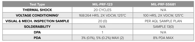
1 The main difference between the two specifications in regards to voltage conditioning is that components tested under MIL-PRF-123 are monitored, and during the last 48 hours of testing must pass the specified PDA.
POTENTIAL FAILURE MODES TO SCREENS FOR
When we screen parts using the MIL-SPECS detailed above, there are a variety of potential failure modes we screen for including the following:
- Gaps between the electrode and terminal that cause internal arcing
- A lack of termination coverage
- Current leakage due to
- Cracks
- Contamination of layers
- Delamination
- Large voids within the internal ceramic layers
CONCLUSION
As a medical device designer, it’s important to have a general understanding of MIL-SPECs, the parts screening process, and potential failure modes before deciding on the medical implantable-grade MLCCs that are right for the specific medical device.
By having this level of understanding, design engineers can better discuss its needs with potential suppliers.