


Inductors and RF chokes are basically the same type of electrical components. The difference in design is related to the function the device will perform in a circuit. Most engineers are more familiar with inductors – some think both devices can be used interchangeably – that are prevalent in frequency selective systems, such as a tuner for radio receivers or filters.
Inductors
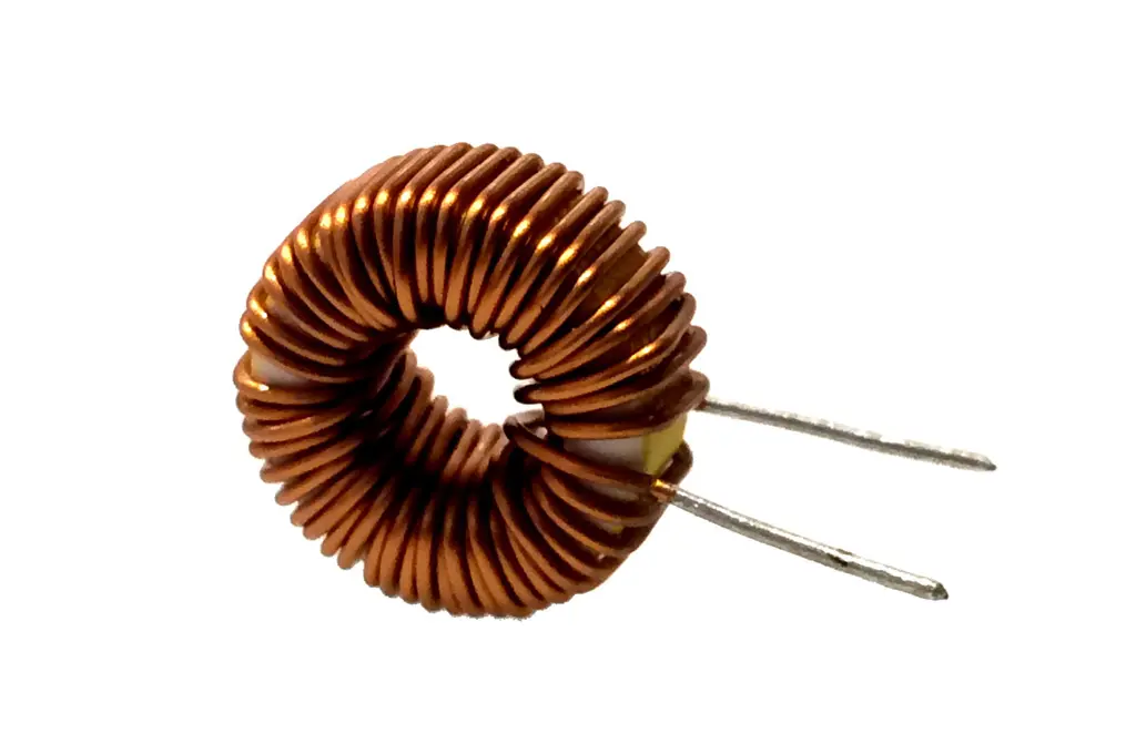
A standard inductor is created by tightly wrapping wires (coils) around a solid rod or a cylindrical ring called the core of the inductor. When current circulates on the wires, a magnetic flux is created that is opposite to the change in current (resisting any change in the electrical current) but proportional to the value of the current. In addition, a voltage is induced in the coil due to the movement of the magnetic flux. The strength of the magnetic flux is related to the type of core.
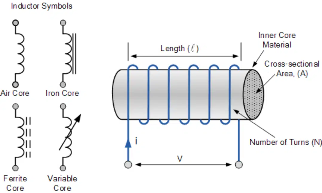
Inductors are classified according to the type of core the coil is wound around. Figure 1 shows the symbols used to distinguish some of the types.
Units
As we saw, inductors resist the change in current (AC) but easily allow the passage of DC current. This ability to oppose changes in current and the relationship between current flow and magnetic flux in the inductor is measured with a figure of merit called inductance, with symbol L and units of Henry (H), after the American scientist and first Secretary of the Smithsonian, Joseph Henry.
RF Chokes
We can think of RF chokes as applications of inductors. They are designed as fixed inductors with the purpose of choking off or suppressing high-frequency alternating current (AC) signals, including signals from radio frequency (RF) devices, and allowing the passage of low-frequency and DC signals. Strictly speaking, ideally an RF choke is an inductor that rejects all frequencies and passes only DC. To achieve this, the choke (or the inductor) must have a high impedance over the range of frequencies it is designed to suppress, as we can see by inspecting the formula for the value of the impedance, XL:
XL = 6.283*f*L
Where f is the frequency of the signal and L is the inductance. We see that the higher the frequency, the higher the impedance, so a signal with high frequency will encounter an equivalent resistance (impedance) that will block its passage through the choke. Low-frequency and DC signals will pass through with little power loss.
Chokes are normally built with a coil of insulated wires wounded on a magnetic core or a circular-shaped “bead” of ferrite material strung on a wire. They are often wound in complex patterns in order to reduce their self-capacitance.
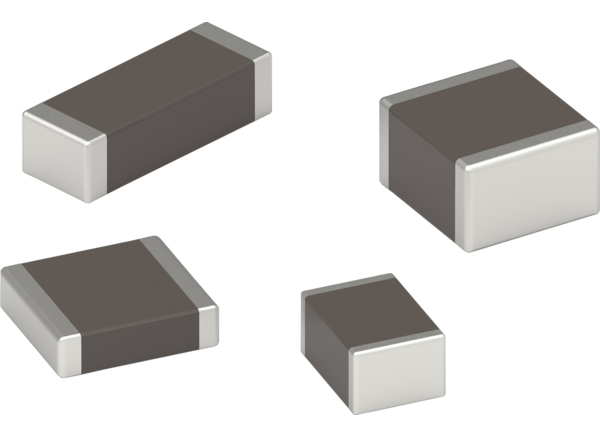
Typically, RF chokes can be seen on computer cables. They are known as ferrite beads and are used to eliminate digital RF noise. As shown in Figure 2, ferrite beads are cylindrical or torus-shaped and normally slipped over a wire.
Self-Resonance
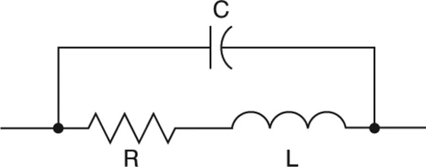
Real world inductors and chokes are not 100 percent inductive. When power is applied there are parasitic elements that alter the behavior of the device and alter impedances. The wires of the coil used to manufacture the inductor always introduce a series resistance, and the spacing between the coil turns (normally separated by insulation) produce a parasitic capacitance. This element appears as a parallel component to the series combination of the parasitic resistor and the ideal inductor. A typical equivalent circuit of an inductor is shown in Figure 3.
The reactance of the ideal inductor and the parasitic capacitor are given by the known formulas:
XL = wL = 6.283*f*L (1)
XC = 1/(wC) = 1/(6.283*f*C) (2)
Because of the existence of reactances the value of the total impedance of the circuit changes with frequency. As the frequency increases the capacitor reactance drops while the inductor capacitance increases. There is a frequency at which both the reactance of the ideal inductor and that of the parasitic capacitor are equal. This is called the self-resonant frequency of the parallel resonant system. In a parallel resonant circuit, the total impedance at the resonant frequency is maximum and purely resistive. Figure 4 shows the plots of impedance versus frequency, as given by equations 1 (in red) and 2 (in blue). The total impedance (in black) shows the resonant frequency at the point where both impedances are equal. The impedance at this point is purely resistive and has a maximum value.
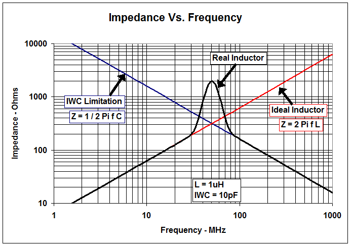
Figure 4. Impedance vs. Frequency. Source: Texas Instruments


