


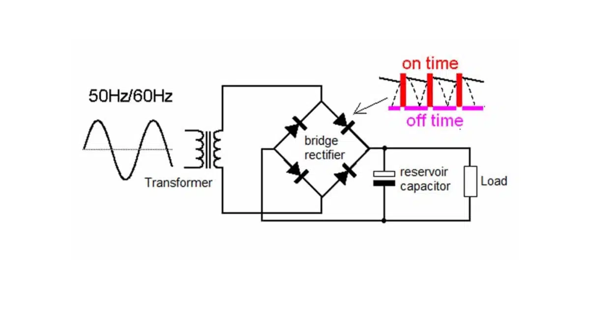
Large voltage spikes are common in power circuits, especially during switching. Switching devices are exposed to large spikes during turn-off, and voltage suppression circuits are required to protect them.
Key Takeaways
- Snubber capacitors protect switching devices from harmful voltage spikes during operation, improving reliability and efficiency.
- RC and RCD snubbers are the two most common designs; RC snubbers help minimize voltage spikes, while RCD snubbers reduce losses and improve load lines.
- Polypropylene film capacitors are preferred for snubber applications due to their stability and ability to withstand high voltage transients.
- Ceramic and mica capacitors are suitable for low-power applications, while polypropylene capacitors perform well in both low and high-power circuits.
- Implementing snubber capacitors efficiently reduces EMI and protects components, making them essential in various power circuits.
Circuits for protecting FETs, IGBTs and other switching devices from large voltage spikes produced during switching operations are commonly referred to as snubbers and snubber capacitors.
Snubber Circuits
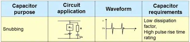
A snubber is an essential part of a power conversion circuit. Snubbers are used in power circuits for a broad array of applications including reducing or eliminating voltage or current spikes, limiting dV/dt, or dI/dt, reducing electromagnetic interference (EMI), reducing losses caused by switching operations, shaping load lines, and transferring power dissipation to resistors or useful loads.
A “hard switching” operation subjects a switch to voltage and current stress and causes high switching loss. Presence of parasitic capacitance and parasitic inductance increases this stress further. The total parasitic capacitance comprises of stray capacitance and junction capacitance while the total parasitic inductance comprises of lead inductance and inductance due to circuit layout. Using good circuit layout practices helps to minimize parasitic inductance.
Layout and EMI considerations
The effectiveness of a snubber is strongly influenced by the physical layout of the components and the associated current loops. The snubber capacitor and any associated resistor or diode should be placed as close as possible to the protected device terminals to minimize the loop inductance between the switch, snubber, and return path.
Short, wide traces or planes are preferred for the snubber connections, and unnecessary vias or long trace runs should be avoided. Poor placement can introduce additional stray inductance that reduces the effectiveness of the snubber and may even increase ringing or EMI. Careful routing also helps to keep high‑dV/dt and high‑di/dt loops away from sensitive control and measurement circuits, improving overall electromagnetic compatibility.
Although the electronic circuits of motor drives, lamp ballasts, power converters, and other power devices may be different, most have common switch-diode-inductor networks and waveforms. The most common circuits are buck, boost, buck-boost, and inverter pole networks. Power electronic circuits that share a common switch-diode-inductor network have same snubber requirements since the behavior of the fundamental network is identical.
Waveforms and stored energy
The need for a snubber is best understood from the energy stored in parasitic inductances and the resulting waveforms at the switching node. When a switch opens, the energy stored in leakage inductance must be transferred somewhere; if no path is provided, the voltage rises until a clamp or device breakdown limits it.
A snubber capacitor provides a controlled path for this energy, converting it into a voltage ramp rather than an abrupt spike. The value of the snubber capacitance directly affects the peak voltage, the ringing frequency with the parasitic inductances, and the energy dissipated per switching cycle. The associated snubber resistor is then chosen to damp the resonant LC formed by the parasitic inductance and the snubber capacitance, trading off residual ringing against additional loss.
Types of snubber circuits
Snubber circuits can be broadly categorized by how they are connected in the power stage and which stress they primarily address. The most common implementations are turn‑off snubbers across the main switch, clamp snubbers across a transformer winding, and damping networks across diodes or inductors.
In practical power electronics, these functions are realized using a handful of standard topologies:
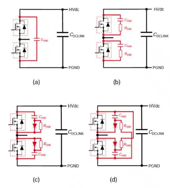
- C snubber: A single capacitor connected across the switch or winding, primarily limiting peak voltage and slowing dV/dt.
- RC snubber: A resistor–capacitor network that both limits voltage overshoot and damps ringing caused by parasitic inductance and capacitance.
- RCD clamp snubber: A resistor–capacitor–diode network that clamps the voltage by diverting energy into a dissipative path, often returning it to the input or a reservoir.
- Non‑discharge RCD snubber: A variant where the capacitor does not fully discharge each cycle and mainly limits peak voltage.
The same basic RC and RCD building blocks can be used in buck, boost, flyback, forward, and inverter pole networks, because each topology shares a similar switch–diode–inductor structure and comparable transient waveforms. The choice between C, RC, and RCD snubbers depends on the allowed losses, acceptable complexity, and required control of peak voltage and ringing.
In most practical designs, the resistor–capacitor (RC) and resistor–capacitor–diode (RCD) snubbers are the default choices. An RC snubber suppresses peak voltage and damps ringing by dissipating energy in the resistor each switching cycle, which makes it attractive in low and medium power stages. An RCD snubber introduces a unidirectional path for the current via the diode and can reduce average losses by steering energy into a controlled dissipative path or back into the circuit, at the expense of higher complexity and sensitivity to component selection.
Most of today’s high voltage inverter circuits use IGBTs as the switching devices. IGBTs have lower conduction losses and occupy a smaller die area compared to MOSFETS, and this makes them a better choice for hard switching applications. A significant increase in switching losses at high frequencies makes IGBT modules unsuitable for applications exceeding 20 KHz. Since IGBTs can switch high currents within short time frames, they are exposed to potentially harmful voltage transients and therefore require protection circuits. Adding a snubber capacitor across the IGBT diverts the inductive current thus protecting the switch.
RC snubbers are mostly used in low power and medium power applications. In high power applications, these snubbers exhibit excessive power losses making them unsuitable for such applications. In comparison, RCD snubbers are suitable for medium current and high current applications. They are commonly used for protecting various switching devices including IGBT modules. In high current applications, RC snubbers are mostly used for secondary damping. See also article RC snubber design for SMPS protection.
Snubber Capacitors
Snubber circuits are exposed to high stress, so it is important to select components that can withstand such conditions. The types of capacitors that are widely used for snubber applications include film and ceramic capacitors. Whereas plastic film capacitors can be used for both high power and low power circuits, ceramic capacitors are mostly used for low power applications.
A snubber capacitor is a capacitor connected to a high-current switching node. It’s designed to protect electronics from voltage spikes and transients that can occur during switching.
It’s common for the actions of a switch (i.e., opening or closing) to induce a high voltage across a device. Those voltage spikes cause failures if they exceed component ratings.
Snubber capacitors offer an alternate path for excess energy to be absorbed and dissipated, ultimately reducing voltage spikes and ringing effects. Implementing snubber capacitors improves efficiency, reduces EMI and protects components.
While there are many snubber designs, resistor-capacitor (RC) and resistor-capacitor-diode (RCD) are the most common. RC snubbers suppress peak voltage and minimize ringing; RCD snubbers have the additional benefit of reducing circuit loss, but the diode across the resistor causes resistance to reduce to zero while the capacitor is charging. Worth noting!
Snubber capacitors are powerful tools for improving circuit reliability and efficiency. They allow aps to leverage the benefits of switching without the potentially harmful effects of voltage spikes.
Capacitors used in snubber circuits are subjected to high dV/dt and extremely high values of peak and rms current. These circuits demand capacitors that can withstand current spikes with high peak and rms values. The characteristics of polypropylene film capacitors make them suitable for snubber applications.
Film capacitors for snubber applications
Most snubber capacitors are designed with polypropylene material. The performance characteristics of this low-loss dielectric material make it suitable for designing capacitors for use in both low and high pulse applications. The properties of a film capacitor are significantly dependent on the construction technology used.
Metallized film capacitors, also commonly known as metallized electrode capacitors, have self-healing properties while discrete foil electrode capacitors do not have them. Polypropylene film/foil capacitors are commonly used as snubber capacitors in low pulse applications. In comparison, polypropylene metallized film capacitors and double sided metallized film capacitors have self-healing property, and they are suitable for use in low pulse and medium pulse applications. These two types of capacitors are suitable for protecting various switching devices including thyristors, FETs, and IGBT modules. Some polypropylene metallized film capacitors are specially designed for direct mounting on IGBT modules.
A hybrid electrode capacitor is a combination of metallized electrode and discrete foil technologies. These capacitors are used in applications that expose capacitors to extremely high in-rush currents, voltage stress, and dV/dt. Hybrid electrode capacitors have self-healing property, and they are commonly used as snubber capacitors in high pulse applications.
Polypropylene capacitors offer high tolerance and stability. Changes in temperature or applied voltage have minimal effects on the performance characteristics of these components. Furthermore, polypropylene capacitors have low and virtually linear temperature coefficient. The high stability of capacitance of polypropylene capacitors makes them a suitable option for snubber applications.
Snubber circuits subject components to extremely high voltage transients and demand components that can withstand high voltages. Polypropylene capacitors can withstand high voltages, and components with operating voltage ratings of 1 kV, 2kV, 3kVand above are commonly available. Furthermore, snubber applications demand components with low equivalent series resistance (ESR) and equivalent series inductance (ESL). Polypropylene capacitors have low ESR and ESL.
Apart from applications in circuits with extremely high peak current levels, polypropylene capacitors are also suitable for switching power supplies, precision timing circuits, high pulse discharge circuits, sample and hold circuits, and high frequency resonant circuits. These capacitors are usually available as leaded components.
Ceramic capacitors for snubber applications
Multilayer ceramic (MLCC) capacitors have many applications in today’s electronic circuits. These passive components are broadly classified into three classes: Class I, Class II, and Class III. Class I capacitors are designed with low-K materials such as calcium zirconate (CaZrO3) while Class II and III capacitors are based on high-K materials such as barium titanate (BaTiO3).
Since calcium zirconate (CaZrO3) and titanium oxide (TiO3) have low relative permittivity, they yield capacitors with low capacitance. These temperature compensating capacitors have high stability of capacitance and are suitable for snubber applications. Class I capacitors have fairly linear temperature characteristics. Changes in voltage have minimal effects on the characteristics of these capacitors. Furthermore, Class I capacitors are not susceptible to aging.
Choosing between film, ceramic and mica
Polypropylene film capacitors are typically the first choice for snubbers in medium and high‑power converters, because they combine high pulse current capability, low loss, and stable capacitance over temperature and voltage. MLCC Class I ceramic capacitors are attractive in low‑power and high‑frequency circuits where small values and compact size are sufficient, but their available capacitance is usually limited compared with film devices.
Mica capacitors offer very high stability and low inductive and resistive losses, making them suitable where small capacitance, high Q, and predictable behavior are required. In contrast, high‑K Class II ceramics exhibit significant capacitance change with bias and temperature, and may introduce microphonic effects, so they are generally less preferred for demanding snubber applications. Dedicated snubber film capacitor series from manufacturers often specify dv/dt, peak current, and pulse endurance ratings explicitly, which should be carefully considered during component selection.
Unlike polypropylene film capacitors, MLC capacitors are mostly used in low power applications. Apart from MLC capacitors and film capacitors, mica capacitors are also used as snubber capacitors. These capacitors have high stability and low inductive and resistive losses. Mica capacitors are suitable for low pulse applications.
Application examples
SMPS primary snubbers
In flyback and forward converters, snubber capacitors are commonly connected across the primary switch or across the primary winding to absorb energy from leakage inductance and limit drain or collector overshoot. Properly designed RC or RCD snubbers reduce peak stress on the switch and improve waveform quality on both primary and secondary side, often in combination with clamp circuits on the transformer. For a detailed discussion of RC snubber design in SMPS, see the referenced articles on RC snubber design for SMPS protection.
Inverter and motor drive snubbers
In high‑voltage inverters and motor drives based on IGBTs or SiC devices, snubber capacitors are used at the device level and sometimes across the DC bus or motor terminals. Device‑mounted snubbers can limit local overvoltages at the module terminals, while bus or output snubbers help to control transients caused by long cable inductances and rapidly changing currents. The choice between RC and RCD configurations depends on the permitted loss, switching frequency, and the topology of the motor drive.
High-frequency resonant converters
In resonant topologies such as LLC converters, snubber networks may serve both as protection and as part of the overall resonance shaping. Here, the snubber capacitance and resistance must be coordinated with the main resonant tank to avoid unwanted shifts in frequency response or efficiency. Even in so‑called “soft‑switching” circuits, localized parasitics can still create high‑frequency oscillations that benefit from carefully placed snubber capacitors.
Reliability, testing and derating
Snubber capacitors operate under repetitive high‑stress conditions, so appropriate voltage, current, and temperature derating is essential for long‑term reliability. In addition to the DC or rms operating voltage, designers must consider peak pulse voltage and dv/dt, ensuring that the chosen capacitors are rated for the expected pulse profile and ambient conditions.
Typical failure mechanisms include dielectric breakdown, excessive self‑healing energy in metallized film capacitors, electrode erosion, or mechanical cracking in ceramic capacitors due to thermal or mechanical stress. To validate a snubber design, endurance tests with representative switching waveforms and thermal measurements are recommended, together with checks for long‑term drift of capacitance and dissipation factor. Following manufacturer application notes and applying conservative derating margins for voltage and temperature greatly reduces the risk of premature failures in demanding power electronics applications.
Conclusion
Switchers produce potentially harmful voltage spikes that can damage electronic components. Snubbers are used in power circuits to suppress harmful voltage transient spikes. Apart from limiting voltage transients, snubbers are also used for shaping load lines, limiting dV/dt, reducing switching losses, transferring power dissipation from switches, and reducing voltage and current ringing. The performance characteristics of polypropylene capacitors make them a suitable choice for snubber circuits, AC filtering, and DC-link applications. Polypropylene film capacitors are suitable for both low power and high power applications. In comparison, ceramic and mica snubber capacitors are mostly used in low power equipment. Snubber capacitors are common in inverter/converter, welding equipment, uninterruptible power supply (UPS), and motor controls circuits.
FAQ – Snubber Capacitors: User’s Guide
A snubber capacitor is a capacitor connected across a high-current switching node, designed to protect electronic circuits from voltage spikes and transients during switching events. It provides a path to absorb and dissipate excess energy, reducing voltage spikes and increasing circuit reliability.
Snubber capacitors are used to suppress potentially damaging voltage and current spikes, reduce electromagnetic interference (EMI), limit dV/dt and dI/dt, shape load lines, and improve the overall efficiency and safety of switching devices like FETs and IGBTs.
Polypropylene film capacitors are most commonly recommended for both low and high power applications due to their low-loss, high-stability, and excellent voltage endurance. Ceramic capacitors (especially multilayer ceramic/MLCC) and mica capacitors are also suitable, particularly for low power and high-frequency use.
RC snubber circuits (resistor-capacitor) suppress peak voltage and minimize ringing, commonly used in low and medium power applications. RCD snubber circuits (resistor-capacitor-diode) add a diode to further reduce losses and improve efficiency but change the current path when the capacitor is charging, making them ideal for medium to high current scenarios.
They are frequently found in inverter/converter circuits, welding equipment, UPS systems, motor controls, and high-frequency resonant circuits—anywhere switching devices need protection from voltage transients.
How-to Use and Select Snubber Capacitors
- Assess Circuit Requirements
Identify if your application involves switching devices (e.g., FETs, IGBTs) prone to voltage transients and spikes. Determine the voltage and current stress levels.
- Choose the Snubber Type
Select an appropriate snubber circuit design, such as RC for lower power and RCD for higher power or more demanding applications.
- Select the Capacitor Type
For high reliability and stability, use polypropylene film capacitors for both high- and low-power applications. Use MLCC (ceramic) or mica capacitors for low-power or high-frequency designs.
- Calculate Key Parameters
Determine required capacitance, voltage, and current ratings, ensuring the chosen component can withstand high dV/dt, peak and RMS currents. Factor in ESR and ESL requirements for efficiency and reduced losses.
- Example: RC snubber in a flyback converter
Consider a flyback converter where the primary leakage inductance is estimated as 1 µH and the peak primary current at turn‑off is 5 A. The stored energy in the leakage inductance is then approximately 12.5 µJ per switching cycle, which must be absorbed by the snubber. If the design goal is to limit the drain or collector voltage overshoot to a defined percentage above the nominal value, a snubber capacitor can be selected to shape the voltage rise and reduce the peak. The associated resistor is then chosen to critically or optimally damp the resulting LC resonance, balancing reduced ringing against acceptable additional loss. A more detailed, step‑by‑step derivation of capacitor and resistor values for typical SMPS topologies is available in the RC snubber design articles linked at the end of this guide.
- Implement in the Circuit
Install the snubber capacitor at the high-current switching node. Ensure proper layout to minimize parasitic inductance and optimize performance.
- Verify Functionality
Test for reduced voltage spikes and improved waveform quality. Check component temperature and operation integrity under load.
Continue reading:


