


For some the words solenoid and relay conjure visions of an ancient electromechanical world now replaced by all-electronic devices, smart motors, and more. That almost makes sense, as these two components in various forms have been with us for over 150 years. But don’t be fooled: Both are still indispensable devices … and remain viable choices for the conversion of electrical energy to mechanical motion (in the case of solenoids) or where a signal must control the on-off path of one or more other signals (in the case of relays). Let’s compare these two electrical components — having very different uses but employing very similar physics.
What is a solenoid?
In basic terms, a solenoid is a helically wound coil with a hollow center along its longitudinal axis. Within this coil there is a free-floating plunger of magnetic material that retracts or extends along that axis — with a head to one of the hollow’s ends.
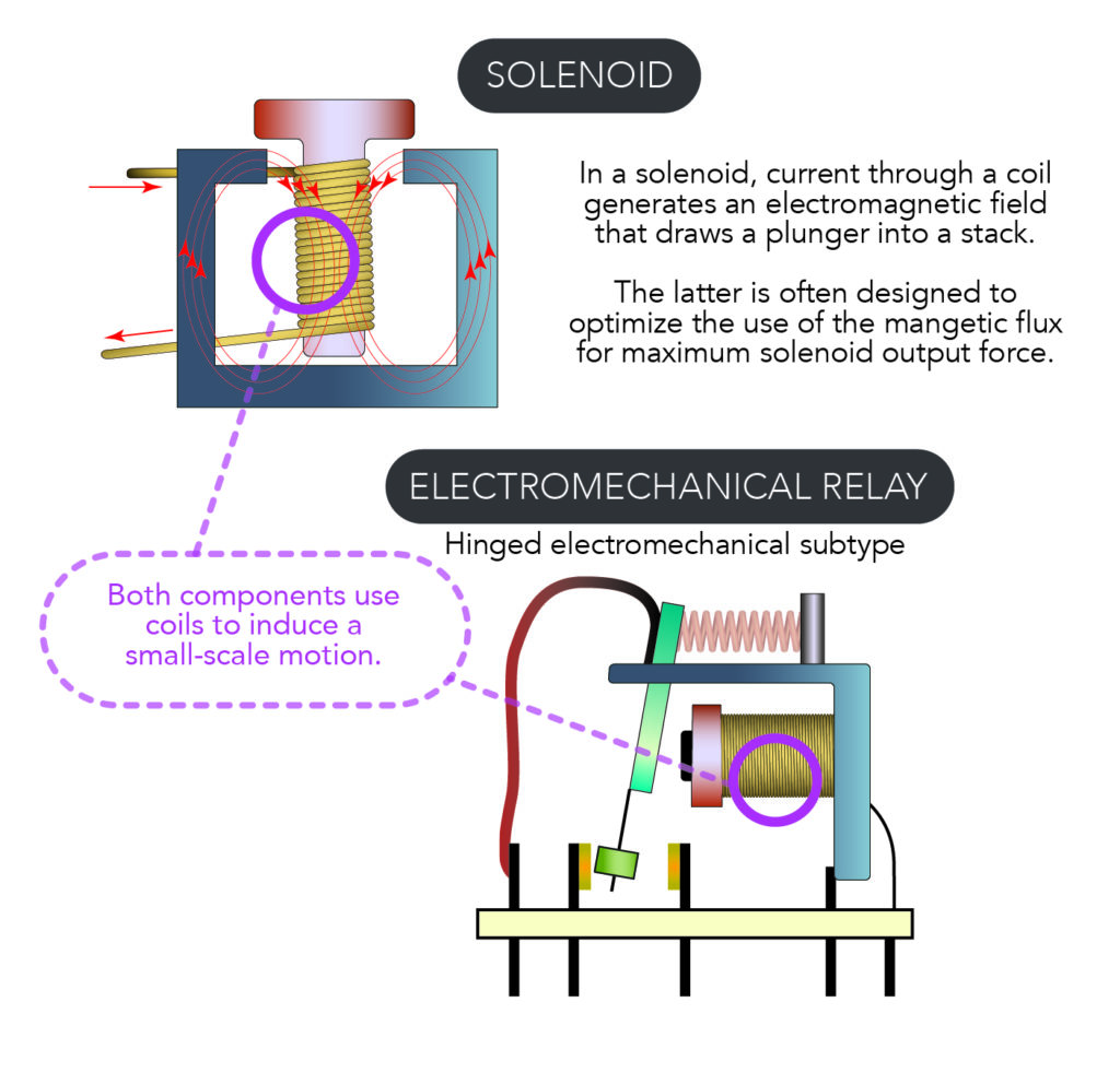
Used in automated systems for many decades, solenoids and relays are still vital components — especially where versatility, ruggedness, ease of use, and flexibility are required for linear motion or circuit switching. In a solenoid, a magnetic field of an energized coil moves a captive metal plunger. When power is removed, the plunger returns to a neutral position. In contrast, an electromechanical relay has an armature which moves and closes (or opens) a contact circuit when the coil is energized and generates a magnetic field.
Where are solenoids used? Solenoids excel in places needing sharp and quick linear motion over a limited range. Of course solenoids vary in size and power, but typical sizes range from one to six inches in length with linear motion of the same range. Depending on the wire turns and applied current, solenoids can apply sub-ounce to very large impact forces capable of punching holes in metal or forming rivet heads. Among the many solenoid applications are the opening and closing of locks, motions on industrial machinery, and dispensing in vending machines … and anywhere else a machine design needs a solid linear stroke or punching action.
How is the solenoid’s force determined? Solenoid output force is expressed by equations based on Ampere’s Law. These define output in terms of number of turns N, armature cross-sectional area A, gap size g, air’s magnetic permeability μO, and applied current i. Note that strength of the output force is proportional to the square of both the current and number of turns. More realistic equations use these parameters and account for coil fringing losses, coil imperfections, and other real-world issues.
How does electrical circuitry drive a solenoid? Like most magnetic devices, the solenoid is a current-driven device — so is best supplied by a true current source. However, because many applications have a voltage source (rail) rather than a current source, solenoids are also specified in terms of their dc resistance … so a voltage source can be used as long as it can supply the needed current as determined by Ohms law.
Does it matter if a design engineer uses a current source or voltage source? Yes and no. Many successful solenoid designs use voltage sources capable of supplying the needed current. However, it may be hard to drive that current properly from the voltage source. That’s because the solenoid’s relatively high transient-current demand may cause the voltage source to “dip” as it tries to supply that current pulse — unless it’s a stiff source with very low lead-wire resistance. that’s why designs use a current source rather than a voltage source wherever possible.
Any other solenoid-drive issues? Most solenoids tend to use a relatively high amount of power —and they dissipate much of this power as heat. That means they run hot and can exhibit both short life and surrounding system degradation. Of course with pulse operation of a solenoid (as in the low duty-cycle situation of a vending machine) this may not be a problem. However, it can be an issue in high-volume high-rate applications on industrial production lines.
What are the other downsides of solenoids? In addition to their fast-transient and high-current requirements, they are difficult to use for precise operation of force or repeatability. That said, smart drivers along with position feedback via Hall-effect devices have greatly improved the capabilities of solenoids.
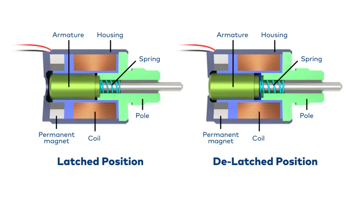
How to enhance and improve solenoid operation? There are two basic solenoid modes. In basic impact mode, the solenoid (upon energization) moves its plunger and impacts with force … and then is deenergized — as when opening a door. In the second mode, the solenoid is energized and held in that mode for a relatively long period — as when a door must be kept unlatched as people pass through. Any use requiring that a solenoid be held in the energized position for more than a brief stroke will cause the generation of heat and the consumption of significant energy. After all, the amount of current required to hold a solenoid is far less than activation current. This is where smart drivers are useful — to activate solenoids at full current and then shift to a much lower hold current.
More on solenoid smart drivers
While it’s possible to drive a solenoid by simply connecting to a suitable voltage rail or current source, a smart driver can do much more. From an electrical perspective, a solenoid is similar to a motor: Both are current-driven and act as highly inductive loads — so the driver requirements are similar as well. No wonder that many components used for motor-coil control (usually metal-oxide semiconductor field-effect transistors called MOSFETs) and their drivers work as solenoid drivers too. For example, certain power-saving solenoid-current controllers run off a 24-Vdc rail. These can serve as a true current source to controls the solenoid current during peak and hold modes — which in turn makes for lower power and thermal dissipation by using PWM drive control via an external MOSFET.
Such smart drivers also let engineers adjust peak current (and time at that current) as well as hold current. They can also enable automatic switchovers from peak-to-hold current mode at the end of the plunger stroke. Some smart drivers even accept an external Hall-effect sensor to track plunger position. Sensing in some cases can let a smart driver detect hard and soft fault conditions … such as shorted or open coils as well as an externally blocked or jammed plunger movement. Although such IC-based drivers require more external passive-support components than a simple power rail in series with the solenoid, they offer far superior performance.
Of course, there are many low-end applications (such as consumer-grade robotics and toys) for which a basic power-source loop sans electronics is adequate and appropriately cost effective.
Reed relays for switching contacts and more
Reed relays are glass-encased contacting relays that excel in dusty and fumy settings. Various sources list reed relays as electromechanical relays (due to their electromagnetic operation and moving elements) while others list them as a subtype of SSRs (due to their widespread use in conjunction with solid-state devices). We categorize reed relays as a fully distinct relay class. During operation of the most common iteration — a normally-open (NO) arrangement — a magnetic field from an electromagnet or coil acts on a pair of closely placed flexible reeds. Ultimately the attractive force of the reeds’ opposite polarity overcomes their stiffness and draws their tips (often gold-plated or of a highly conductive material) into contact. Upon removal of the input, the reeds return to their separated positions.
In fact, reed relays can incorporate reeds in various arrangements and quantities, though the latter is limited by the relays’ coil size. Many coils can handle up to a dozen standard switches; for applications requiring more than that, relay coils can connect in parallel. Miniature reed relays are also available: These are surface-mount devices (SMDs) that fasten directly onto printed circuit boards (PCBs).
Reed relays are often used to switch starter motors and other industrial components.
How relays compare to solenoids
Now let’s consider the design of electromechanical relays. These share many electromagnetic characteristics with solenoids … but have a very different construction and functionality.
The design of an electromechanical relay uses a coil and current drive (or a voltage source) just as a solenoid does. However, the function of the relay is quite different. Despite the availability of alternatives for some applications such as the optical solid-state relay (SSR) and MEMS-based relays, the electromechanical relay is still a vital and versatile component for switching both ac -dc signals and power — and at low and high levels.
As already described, the function of a relay is to allow one signal to control the switching of another circuit, with complete electrical isolation and without any electrical contact between the two circuits.
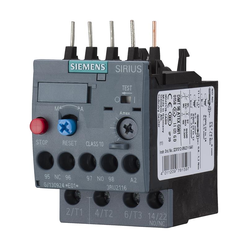
Shown left here is a Siemens SIRIUS 3RU21160EB0 thermal overload relay. Used to provide current-dependent overload protection on a system’s main circuit, it installs into system load feeders. A setting range of 0.28 to 0.4 A allows protection of motors and systems to 0.09 kW. Auxiliary contacts include one that is normally closed (NC) and one that is normally open (NO).
Electromechanical-relay benefits
Reasons abound for the unique and enduring utility of electromechanical relays — even with the availability of SSRs and MEMS relays.
◾️ The coil circuit and the contact circuit are completely isolated from each other and can have very different voltage and current levels.
◾️ The electromechanical relay contact forms a basic switch closure … and current through it can be ac or dc — independent of the coil drive. Neither side of the closure is grounded or connected to circuit common, so the closure can be placed anywhere in a circuit.
◾️ An electromechanical relay can close a contact on activation (called normally open or NO) or it can open a contact (in normally closed or NC designs). Electromechanical relays can also do both using multiple contacts.
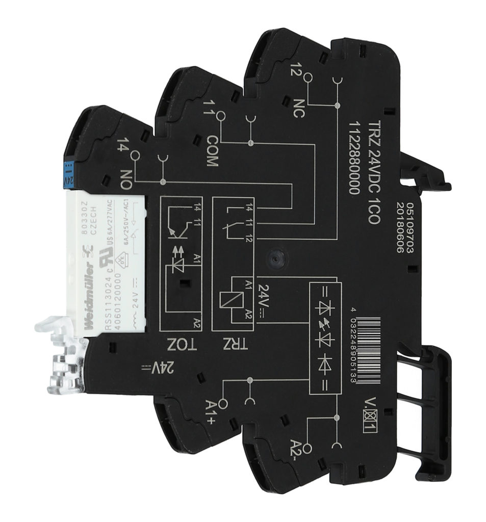
This general-purpose TRZ 24VDC 1CO – 1122880000 coupling relay on right from Weidmüller has spring-loaded push-in terminal contacts to make system wiring easy and reliable. The coupling relay accepts 24 Vdc input and integrates a changeover contact for versatile switching. Recall that changeover contacts (termed Form C contacts) combine the functions of NO (Form A) and NC (Form B) circuits … and are often complemented with other electronics to perform specific tasks.
◾️ Many relays control multiple NO and NC contacts — with three, four, or even more independent NO and NC contacts. These multiple contacts don’t need to be carrying the same type and rating of loads … so some contacts can be for low-level signals while others can be for power.
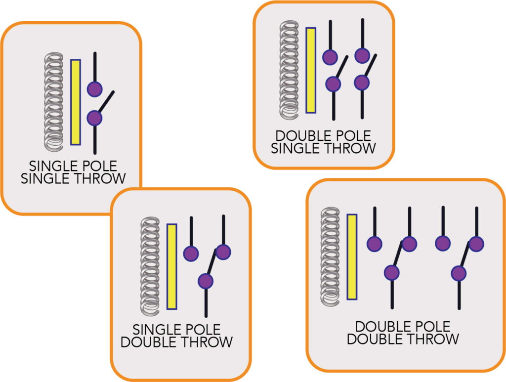
Relay-contact configurations include single pole-single throw (SPST), single pole-double throw (SPDT), double pole-single throw (DPST), and double pole-double throw (DPDT).
◾️ The contact circuit doesn’t need to be live when the relay is activated — which is actually a necessity in some designs. That means the relay can be switched while the load circuit is off. This is called a dry-contact closure.
◾️ Electromechanical relays are electrically and mechanically rugged and robust, and simple to troubleshoot. They can also withstand transients that would damage a solid-state equivalent. https://www.youtube.com/embed/CbUO3LxUzYc
◾️ Electromechanical relays are commonly designed for coil currents from 10 mA up to a couple dozen amps, with contacts handling milliamps and a few volts to several orders of magnitude greater for both parameters.
◾️ Once an electromechanical relay is energized and the armature has moved, it only needs a weaker field to hold it in place; thus, the relay holding current is far less than the actuation current — typically about half. This is the same as with the solenoid, and the same or very similar circuit can be used as a solenoid driver or a relay driver. In addition, the relay load doesn’t need to be fully known or defined as long as it’s within the design limits; this is useful in cases where the load may have uncertain or hard-to-control characteristics.
◾️ A properly designed relay can use low-level voltage-current to switch a much higher voltage-current. In addition, relays are very easy to troubleshoot: All that’s needed is an ohmmeter to measure coil continuity and dc resistance … and to measure the contact resistance when the relay is open and closed.
◾️ Relays can also be used to switch RF signals, though these require unique internal construction.
Comparing relays with contactors
Relays and contactors are electrical switches with the same basic operation — which is why some engineers consider contactors to be a subset of relays. The difference between relays and contactors is where they’re suitable for use: Relays most commonly act upon smaller circuits having ampacity of 20 A or less. In contrast, contactors act upon high-power circuits … directly switching circuits associated with high-current loads such as lights, large capacitors, and integral-horsepower electric motors.
We’ve explained the construction of electromechanical relays already: Just like relays, contactors employ an electromagnetic coil for opening and closing an electrical circuit. However, with contactors, this coil is always on its own power supply. However, contactors have one or more pairs of NO three-phase inputs and outputs … and in some instances, auxiliary contacts that operate with the main contacts.
Many contactors used on electric motors (to establish and interrupt the power into the windings) also integrate thermal-overload protection at each winding. Low-resistance metal bands warm as the windings draw current. Upon detection of overheating, they trigger an NC contact (in series with the contactor’s electromagnetic coil) to open … that in turn deenergizes the contactor — and cuts the motor off from power.
Contactor formats typically adhere to NEMA or IEC standards. The latter tend to be smaller for a given rating as well as less reliant on mass to dissipate heat from arcing — thanks to use of complementary contacts (and blowout coils) for electromagnetic arc quenching. Also integrated into the design of many contactors are arc chutes (closed spaces walled by parallel plates) for arc suppression and the extinguishing of arcs.
Electromechanical-relay drawbacks
❌ Electromechanical relays are well suited for some situations — and not for others. They can be relatively slow, with switching speeds on the order of tens of milliseconds. This is unacceptable for those switching applications which need microsecond-range or faster speeds.
❌ They will wear out — although a well-designed quality relay used within its design limits can last more than a million cycles, that may not be enough. Not only will the moving mechanical elements wear out, but the electrical contact surface plating will abrade from the repeated make-break action … eventually making poor or intermittent contact.
❌ Unless they are sealed, contacts can accumulate dirt and may even corrode (which degrades contact-side performance).
❌ They are larger than SSR or MEMS counterparts and require current driven at relatively high levels — so can consume (and dissipate) significant power … especially when held in an energized mode.
featured image source: TLXTechnologies


