Passive Components Blog
No Result
View All Result
  • Home
  • NewsFilter
    • All
    • Aerospace & Defence
    • Antenna
    • Applications
    • Automotive
    • Capacitors
    • Circuit Protection Devices
    • electro-mechanical news
    • Filters
    • Fuses
    • Inductors
    • Industrial
    • Integrated Passives
    • inter-connect news
    • Market & Supply Chain
    • Market Insights
    • Medical
    • Modelling and Simulation
    • New Materials & Supply
    • New Technologies
    • Non-linear Passives
    • Oscillators
    • Passive Sensors News
    • Resistors
    • RF & Microwave
    • Telecommunication
    • Weekly Digest

    Vishay Releases High‑Current Radial Inductors up to 209 A

    May 2026 Interconnect, Passives and Electromechanical Components Market Insights

    Passive Components Enable Safe and Reliable ADAS Architectures

    Current Sense Transformer Datasheet and Design‑in Guide

    Designing a USB Type‑C Flyback Planar Transformer with Frenetic’s Planar Tool

    YMIN Releases Square Supercapacitors for AI Server Power System

    Exxelia Extends Temperature Range of its PP Film Capacitors to 140C

    How Long-Term Storage Causes Aging in Electronic Components

    Nichicon Presents Self-Charging LTO Board for Maintenance-Free IoT Nodes

    Trending Tags

    • Ripple Current
    • RF
    • Leakage Current
    • Tantalum vs Ceramic
    • Snubber
    • Low ESR
    • Feedthrough
    • Derating
    • Dielectric Constant
    • New Products
    • Market Reports
  • VideoFilter
    • All
    • Antenna videos
    • Capacitor videos
    • Circuit Protection Video
    • Filter videos
    • Fuse videos
    • Inductor videos
    • Inter-Connect Video
    • Non-linear passives videos
    • Oscillator videos
    • Passive sensors videos
    • Resistor videos

    Current Sense Transformer Datasheet and Design‑in Guide

    Designing a USB Type‑C Flyback Planar Transformer with Frenetic’s Planar Tool

    Magnetics Design in High‑Frequency GaN Converters

    Qi2 Wireless Charging: Inductors, Capacitors and EMC Filters

    Two‑capacitor paradox explained for engineers

    Capacitances of Nonlinear MLCCs: What Datasheets Don’t Tell You

    Tapped Inductor Buck Converter Fundamentals

    Planar vs Conventional Transformer: When it Make Sense

    Modeling Fringing Field Losses in Inductors & Transformers

    Trending Tags

    • Capacitors explained
    • Inductors explained
    • Resistors explained
    • Filters explained
    • Application Video Guidelines
    • EMC
    • New Products
    • Ripple Current
    • Simulation
    • Tantalum vs Ceramic
  • Knowledge Blog
  • DossiersNew
  • Suppliers
    • Who is Who
  • PCNS
    • PCNS 2025
    • PCNS 2023
    • PCNS 2021
    • PCNS 2019
    • PCNS 2017
  • Events
No Result
View All Result
Passive Components Blog
No Result
View All Result

Bourns Expanded Semi-Shielded Low Profile Automotive Power Inductor

12.3.2026
Reading Time: 5 mins read
A A

Bourns has expanded its SRN3010BTA series of semi‑shielded power inductors with a new 33 µH variant aimed at compact automotive and industrial power designs.

The new power inductor combines AEC‑Q200 qualification, a 1 mm maximum height and soldered lead‑wire construction to support higher reliability where board space and long‑term robustness are critical.

RelatedPosts

Bourns Releases Compact High Current Shielded Power Inductors

Bourns Expands its Modular Contacts for Power-Dense Systems

Bourns Extends PPTC Resettable High‑Power, High‑Voltage Protection Fuses

Key features and benefits

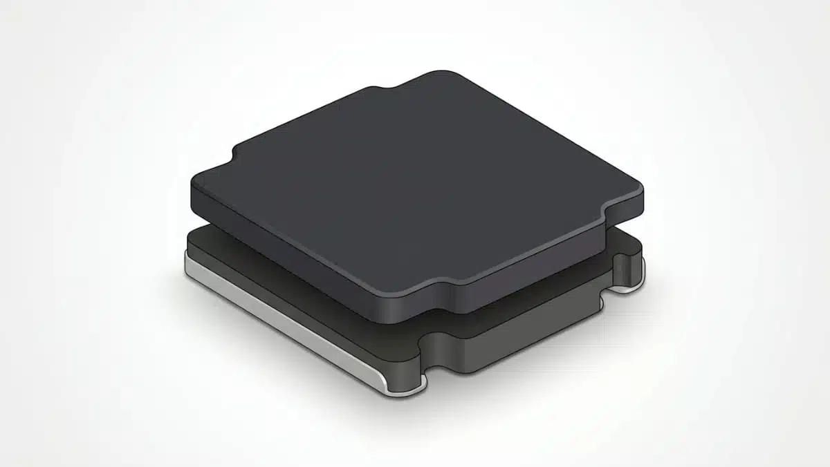
The SRN3010BTA series targets compact DC‑DC converter and power supply stages where a low‑profile, semi‑shielded inductor is required rather than a full molded or open construction. The newly added model is SRN3010BTA‑330M with the following headline parameters according to the manufacturer datasheet:

  • Inductance: 33 µH nominal
  • Package size: 3 mm × 3 mm footprint, 0.9 mm max height (1 mm max profile specified for the series)
  • Semi‑shielded construction
  • Heating current Irms=0.60 AI_{\text{rms}} = 0.60 \,\text{A} (temperature rise defined per datasheet)
  • Saturation current Isat=0.45 AI_{\text{sat}} = 0.45 \,\text{A}
  • Operating temperature range: −55 °C to +125 °C
  • AEC‑Q200 compliant automotive grade
  • RoHS compliant and halogen free as defined by the manufacturer

Semi‑shielded inductors typically use a composite magnetic material around the winding, which reduces radiated EMI compared with open inductors while still offering cost and height advantages versus fully molded shielded types. In this case, the 1 mm profile is especially attractive for slim automotive ECUs, infotainment modules and low‑profile consumer/industrial boards where z‑height is a primary constraint.

The series also utilizes soldered lead‑wire construction for the internal connection between the coil and terminations, which helps improve mechanical robustness and long‑term reliability under automotive vibration and thermal cycling. For engineers designing for elevated temperature and long operating life, this construction detail can be an important differentiator versus low‑cost alternatives.

Typical applications

Bourns positions the SRN3010BTA series for a range of automotive and general‑purpose low‑power DC‑DC conversion tasks. The 33 µH value in particular is suitable where relatively higher inductance is required at modest currents, for example in pre‑regulation or noise‑sensitive stages.

Typical use cases include:

  • Automotive systems and ECUs in body electronics and infotainment
  • Advanced driver assist system boards where board area and height are limited
  • Automotive lighting modules, including LED drivers with compact step‑down converters
  • Low‑power DC‑DC converters in consumer devices that must meet automotive‑grade reliability in harsh environments
  • Point‑of‑load regulators and auxiliary rails in industrial and telecom equipment with tight z‑height limits
  • Noise‑sensitive rails where semi‑shielding helps reduce coupling into adjacent traces or RF sections

In many of these applications, the 33 µH inductance can be used in conjunction with relatively low switching frequencies to reduce ripple current, at the expense of lower saturation current compared with lower‑value inductors. This makes the SRN3010BTA‑330M a candidate for control rails, bias supplies and other non‑primary, low‑power rails in automotive electronics.

Design‑in notes for engineers

When designing in the SRN3010BTA‑330M, several practical points should be checked at the schematic and layout stages:

  • Verify that the peak inductor current in your converter topology stays below the 0.45 A saturation current with adequate margin, considering worst‑case input voltage, load and switching frequency.
  • Confirm that the RMS inductor current remains within the 0.60 A heating current rating for your chosen ripple current and operating temperature rise.
  • Ensure that the −55 °C to +125 °C operating range aligns with the target ambient and hot‑spot temperature in the end application, including self‑heating.
  • Pay attention to PCB copper area around the inductor pads to aid heat dissipation and help keep the component within its thermal budget.
  • In layouts sensitive to EMI, place the semi‑shielded inductor so that its remaining stray field does not interfere with nearby high‑impedance or RF nodes; semi‑shielding reduces but does not eliminate coupling.
  • Where mechanical shock and vibration are concerns (automotive ECUs, under‑hood modules), follow the manufacturer’s recommended land pattern and consider additional board‑level reinforcement strategies as needed.

For power stage optimization, designers can use the series’ available inductance options to trade off ripple current versus transient response and dynamic performance of the DC‑DC converter. The 33 µH value is typically more suited for lower current rails or higher input‑to‑output voltage ratios where a higher inductance helps keep ripple within specification.

Source

This article is based on the official Bourns product extension release for the SRN3010BTA semi‑shielded power inductor series, specifically the announcement of the SRN3010BTA‑330M 33 µH model, complemented by general design considerations for automotive‑grade power inductors according to the manufacturer’s documentation.

References

  1. Bourns IC26024 – SRN3010BTA Series Semi‑shielded Power Inductors Product Extension Release
  2. Bourns official website – Magnetic products overview
  3. Bourns product selector – Inductors

Related

Recent Posts

Vishay Releases High‑Current Radial Inductors up to 209 A

29.5.2026
11

May 2026 Interconnect, Passives and Electromechanical Components Market Insights

29.5.2026
51

Passive Components Enable Safe and Reliable ADAS Architectures

28.5.2026
48

Current Sense Transformer Datasheet and Design‑in Guide

27.5.2026
42

Designing a USB Type‑C Flyback Planar Transformer with Frenetic’s Planar Tool

27.5.2026
26

YMIN Releases Square Supercapacitors for AI Server Power System

27.5.2026
40

Exxelia Extends Temperature Range of its PP Film Capacitors to 140C

27.5.2026
32

How Long-Term Storage Causes Aging in Electronic Components

26.5.2026
83

Nichicon Presents Self-Charging LTO Board for Maintenance-Free IoT Nodes

26.5.2026
22

Upcoming Events

Jun 2
16:00 - 17:00 CEST

Calculation, Simulation and Measurement of 800V EMC Filters

Jun 16
16:00 - 17:00 CEST

EMC with EMC – EMC‑compliant design with electromechanical connectors

View Calendar

Popular Posts

  • Buck Converter Design and Calculation

    0 shares
    Share 0 Tweet 0
  • Boost Converter Design and Calculation

    0 shares
    Share 0 Tweet 0
  • Flyback Converter Design and Calculation

    0 shares
    Share 0 Tweet 0
  • MLCC and Ceramic Capacitors

    0 shares
    Share 0 Tweet 0
  • LLC Resonant Converter Design and Calculation

    0 shares
    Share 0 Tweet 0
  • Capacitor Charging and Discharging

    0 shares
    Share 0 Tweet 0
  • What Electronics Engineer Needs to Know About Passive Low Pass Filters

    0 shares
    Share 0 Tweet 0
  • Dual Active Bridge (DAB) Topology

    0 shares
    Share 0 Tweet 0
  • Ripple Current and its Effects on the Performance of Capacitors

    3 shares
    Share 3 Tweet 0
  • SEPIC Converter Design and Calculation

    0 shares
    Share 0 Tweet 0

Newsletter Subscription


Passive Components Blog

© EPCI - Leading Passive Components Educational and Information Site

  • Home
  • Privacy Policy
  • EPCI Membership & Advertisement
  • About

No Result
View All Result
  • Home
  • Knowledge Blog
  • Dossiers
  • PCNS

© EPCI - Leading Passive Components Educational and Information Site

This website uses cookies. By continuing to use this website you are giving consent to cookies being used. Visit our Privacy and Cookie Policy.
Go to mobile version