Passive Components Blog
No Result
View All Result
  • Home
  • NewsFilter
    • All
    • Aerospace & Defence
    • Antenna
    • Applications
    • Automotive
    • Capacitors
    • Circuit Protection Devices
    • electro-mechanical news
    • Filters
    • Fuses
    • Inductors
    • Industrial
    • Integrated Passives
    • inter-connect news
    • Market & Supply Chain
    • Market Insights
    • Medical
    • Modelling and Simulation
    • New Materials & Supply
    • New Technologies
    • Non-linear Passives
    • Oscillators
    • Passive Sensors News
    • Resistors
    • RF & Microwave
    • Telecommunication
    • Weekly Digest

    Researchers Enhanced 2D Ferromagnets Performance

    Bourns Releases Two High Current Common Mode Choke Models

    Electronics Weekly Announcing Finalists for Elektra Awards 2025

    Exxelia Exhibit at Electronica India September 17–19, 2025

    Würth Elektronik Announces 2025 Digital WE Days Virtual Conference

    VINATech Unveils Hybrid Energy Storage System to Revolutionize Grid Stability and Power Delivery

    SCHURTER Releases High Performance EV-Fuse

    Panasonic Industry to Double Production of MEGTRON PCB Materials

    5th PCNS Awards Outstanding Passive Component Papers

    Trending Tags

    • Ripple Current
    • RF
    • Leakage Current
    • Tantalum vs Ceramic
    • Snubber
    • Low ESR
    • Feedthrough
    • Derating
    • Dielectric Constant
    • New Products
    • Market Reports
  • VideoFilter
    • All
    • Antenna videos
    • Capacitor videos
    • Circuit Protection Video
    • Filter videos
    • Fuse videos
    • Inductor videos
    • Inter-Connect Video
    • Non-linear passives videos
    • Oscillator videos
    • Passive sensors videos
    • Resistor videos

    Ripple Steering in Coupled Inductors: SEPIC Case

    SEPIC Converter with Coupled and Uncoupled Inductors

    Coupled Inductors in SEPIC versus Flyback Converters

    Non-Linear MLCC Class II Capacitor Measurements Challenges

    Percolation Phenomenon and Reliability of Molded Power Inductors in DC/DC converters

    Root Causes and Effects of DC Bias and AC in Ceramic Capacitors

    How to Calculate the Output Capacitor for a Switching Power Supply

    Switched Capacitor Converter Explained

    Understanding Inductor Dot Markings and Their Application in LTspice

    Trending Tags

    • Capacitors explained
    • Inductors explained
    • Resistors explained
    • Filters explained
    • Application Video Guidelines
    • EMC
    • New Products
    • Ripple Current
    • Simulation
    • Tantalum vs Ceramic
  • Knowledge Blog
  • Suppliers
    • Who is Who
  • Events
No Result
View All Result
Passive Components Blog
No Result
View All Result

Space Relays Failures Occurring & Lessons Learnt at ESA

5.2.2025
Reading Time: 3 mins read
A A

source: ESA ESTEC; ESA SPCD 2018 Symposium

EPCI e-symposium library article

RelatedPosts

High-Density PCB Assemblies For Space Applications

Solid State Polymer Multilayer Capacitors For High Temperature Application

Graphene-Based BOSC Bank Of Supercapacitor Cells

ESA component engineers Dr.Denis Lacombe and Dr.Léo Farhat are introducing their presentation on space relays failures and lessons learnt.

published by EPCI under approval of ESA SPCD 2018 organizing committee.


Title: Relays Failures Occurring & Lessons Learnt
Author(s): Dr.Denis Lacombe and Dr.Léo Farhat
Organisation(s): ESA ESTEC, The Netherlands
Symposium: ESA SPCD 2018
Reference: Lessons Learned and In-flight Experiences
ISBN: N/A
e-Sessions Applications: Aerospace
e-Sessions Scope Components: Relays, Inductors
e-Sessions Topics: Technology, Materials, Quality & Reliability


INTRODUCTION

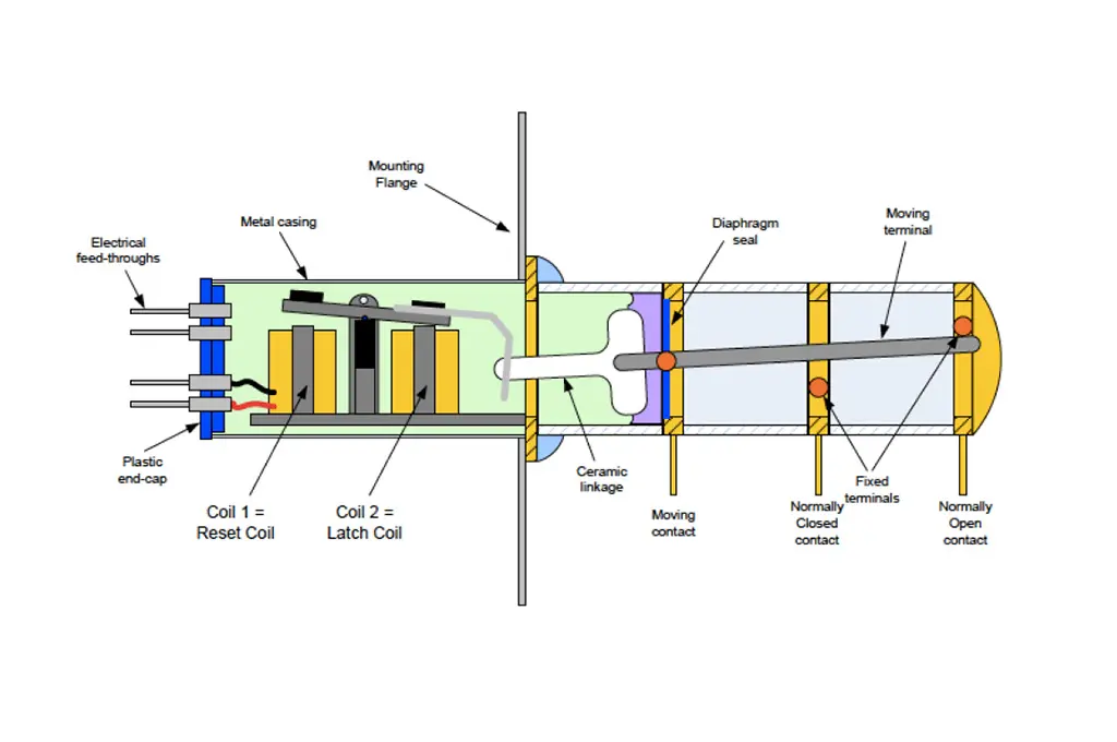
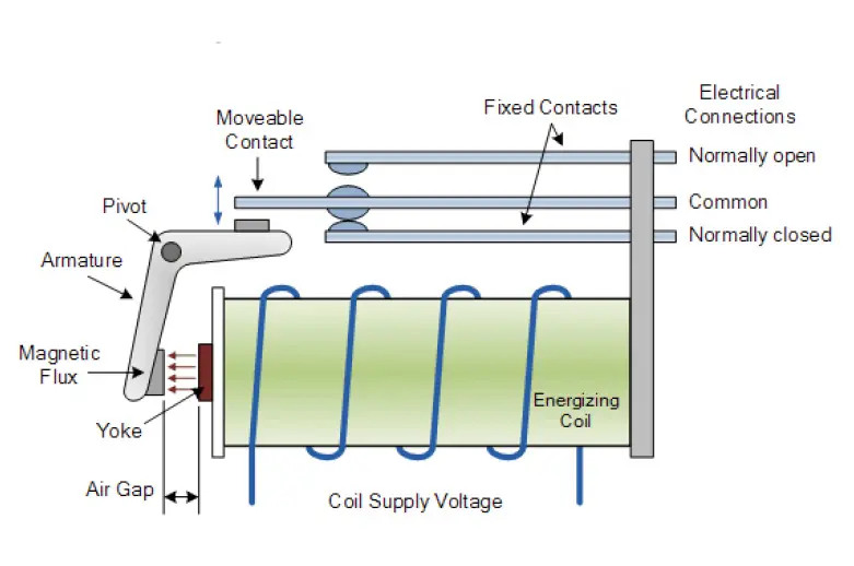
“An electromechanical relay is an electrical switching device. Its function corresponds to a mechanical switch, which is electrically actuated. The main advantages of electromechanical relays are the electrical isolation of the driving system and the load side, the insulation resistance of open contacts, as well as the low resistance of the closed contacts.”

Contact Material
The choice of the contact material depends on the switching capability of the relays. In general, a trade off is made between low resistance material and abrasive resistance. In space application, contact are usually made with silver for low current, silver oxide for high current and tungsten for high voltage.
Tuning and arcing
The settings of the relays are based on the Holm curves and take into account several elements like the contact materials, the contacts gap, the internal gas inside the cavity, the pressure, etc.
Relay Failures
High voltage relay: increase of latch voltage
Actuator side not in hermetic package then vacuum may induce displacement but also cleaning process may cause damage to the gel.
Failure analysis
Failures’ analysis of relays are tricky
  • Complex device with many pieces’part (40 to more than 100)
  • Risk of losing the defect
  • Interest of new methods (Xray, tomography, FIB)

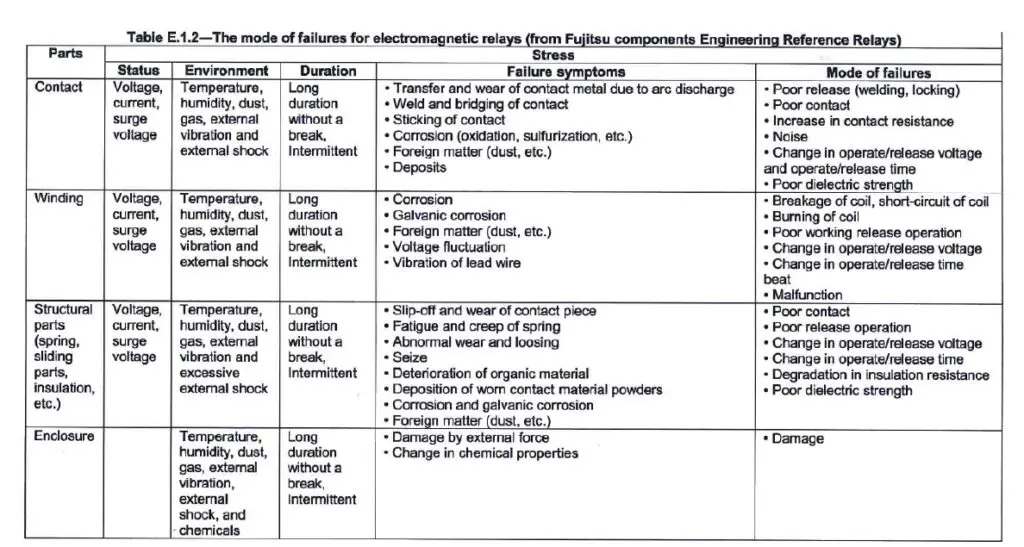
Root cause of observed failures

On 13 observed failures:

  • 3 are due to bad commands
  • 1 is due to bad handling of the relay (soldering)
  • 5 mechanical stress are either the cause or a contributing factor
  • 8 real failures of the relay

5 (≈40%) of the observed failures may have been avoided if better knowledge of relay was used.

… see more at the full presentation link below…

CONCLUSION

ESA alert recommendations

New procurement of ESCC qualified TL26 relays:

  • parts with DC1611 or later shall be preferred.
  • Stock Parts shall be 100% screened by five (5) Monitored Temperature Cycles (-65°C/+125°C) followed by electrical tests at 25 °C as per table 2 of ESCC Detail Specification No. 3602/002.
  • Mounted parts with lot Date Codes identified as Category 2 in Annex 3 shall be subjected to thermal cycling as specified
    below:

    • Minimum 5 cycles
    • Minimum delta temperature of 70°C measured on the relay case. For example, thermal cycles at board level between -20°C to 50°C, Lower delta temperature values are not relevant
    • Duration and transition rate of cycles are not considered as important parameters.
    • The relay shall be switched at high and low temperature during the last cycle of the sequence.

Lesson learnt and recommendations

  • Bad command signal: do not use latch and reset voltage limit
  • Beware of mechanical stress: relay are more sensitive in certain direction then try to use this information to place the relay
  • No switching failure may be intermittent: implement the possibilities to send command signal several times
  • Failure analysis is difficult and need to be carried with care using up to date investigation methods

see the full presentation here:


Related

Recent Posts

Researchers Enhanced 2D Ferromagnets Performance

16.9.2025
2

Bourns Releases Two High Current Common Mode Choke Models

16.9.2025
1

Electronics Weekly Announcing Finalists for Elektra Awards 2025

16.9.2025
3

Exxelia Exhibit at Electronica India September 17–19, 2025

15.9.2025
22

Würth Elektronik Announces 2025 Digital WE Days Virtual Conference

15.9.2025
10

5th PCNS Awards Outstanding Passive Component Papers

14.9.2025
34

KYOCERA AVX Releases Novel Mini BME Stacked Ceramic Capacitors

10.9.2025
25

Würth Elektronik Unveils Compact Common-Mode Data Lines Chokes

3.9.2025
34

Bourns Releases Automotive High Creepage and Clearance Transformer

1.9.2025
31

Bourns Unveils Metal Powder Core High Current Low DCR Shielded Power Inductor

29.8.2025
38

Upcoming Events

Sep 22
September 22 @ 13:00 - September 25 @ 15:15 EDT

Pre Cap Visual Inspection per Mil-Std-883 (TM 2017)

Sep 30
September 30 @ 12:00 - October 2 @ 14:00 EDT

MIL-Std-883 TM 2010

Oct 17
12:00 - 14:00 EDT

External Visual Inspection per MIL-STD-883 TM 2009

Oct 20
October 20 - October 23

Digital WE Days 2025 – Virtual Conference

Oct 21
October 21 @ 12:00 - October 23 @ 14:15 EDT

Space and Military Standards for Hybrids and RF Microwave Modules

View Calendar

Popular Posts

  • Buck Converter Design and Calculation

    0 shares
    Share 0 Tweet 0
  • Boost Converter Design and Calculation

    0 shares
    Share 0 Tweet 0
  • Flyback Converter Design and Calculation

    0 shares
    Share 0 Tweet 0
  • LLC Resonant Converter Design and Calculation

    0 shares
    Share 0 Tweet 0
  • Dual Active Bridge (DAB) Topology Explained

    0 shares
    Share 0 Tweet 0
  • Ripple Current and its Effects on the Performance of Capacitors

    3 shares
    Share 3 Tweet 0
  • What is a Dielectric Constant and DF of Plastic Materials?

    4 shares
    Share 4 Tweet 0
  • SEPIC Converter Design and Calculation

    0 shares
    Share 0 Tweet 0
  • How to Design an Inductor

    0 shares
    Share 0 Tweet 0
  • Core Materials, Permeability and Their Losses

    0 shares
    Share 0 Tweet 0

Newsletter Subscription


Passive Components Blog

© EPCI - Leading Passive Components Educational and Information Site

  • Home
  • Privacy Policy
  • EPCI Membership & Advertisement
  • About

No Result
View All Result
  • Home
  • Knowledge Blog
  • Premium Suppliers

© EPCI - Leading Passive Components Educational and Information Site

This website uses cookies. By continuing to use this website you are giving consent to cookies being used. Visit our Privacy and Cookie Policy.
Go to mobile version