Passive Components Blog
No Result
View All Result
  • Home
  • NewsFilter
    • All
    • Aerospace & Defence
    • Antenna
    • Applications
    • Automotive
    • Capacitors
    • Circuit Protection Devices
    • electro-mechanical news
    • Filters
    • Fuses
    • Inductors
    • Industrial
    • Integrated Passives
    • inter-connect news
    • Market & Supply Chain
    • Market Insights
    • Medical
    • Modelling and Simulation
    • New Materials & Supply
    • New Technologies
    • Non-linear Passives
    • Oscillators
    • Passive Sensors News
    • Resistors
    • RF & Microwave
    • Telecommunication
    • Weekly Digest

    Würth Elektronik Expands Nanocrystalline Cable Cores for Broadband EMI Suppression

    High‑Speed Supercapacitor Balancing for AI Data Center Power Systems

    Bourns Introduced Automotive TVS Diodes for Compact ESD Protection

    EMC‑Compliant PCB and Connector Design Guidelines

    Practical Value of Structural Diagnostics for Tantalum Capacitor Anodes

    Hall-Effect Sensing for Harsh Environments: TT Electronics Selected in NASA’s Dragonfly Fan

    Bourns Releases Automotive Gate Driver Transformer for Isolated Power

    Stackpole Releases High-Frequency Thin Film Chip Resistors for RF up to 50 GHz

    Knowles Expands High‑Q Ceramic Core Inductors for RF designs

    Trending Tags

    • Ripple Current
    • RF
    • Leakage Current
    • Tantalum vs Ceramic
    • Snubber
    • Low ESR
    • Feedthrough
    • Derating
    • Dielectric Constant
    • New Products
    • Market Reports
  • VideoFilter
    • All
    • Antenna videos
    • Capacitor videos
    • Circuit Protection Video
    • Filter videos
    • Fuse videos
    • Inductor videos
    • Inter-Connect Video
    • Non-linear passives videos
    • Oscillator videos
    • Passive sensors videos
    • Resistor videos

    EMC‑Compliant PCB and Connector Design Guidelines

    Why Isolated DC/DC Power Supplies Fail Late, Würth Elektronik Podcast

    Designing 800 V DC EMC Filters: Calculation, Simulation and Measurement

    Current Sense Transformer Datasheet and Design‑in Guide

    Designing a USB Type‑C Flyback Planar Transformer with Frenetic’s Planar Tool

    Magnetics Design in High‑Frequency GaN Converters

    Qi2 Wireless Charging: Inductors, Capacitors and EMC Filters

    Two‑capacitor paradox explained for engineers

    Capacitances of Nonlinear MLCCs: What Datasheets Don’t Tell You

    Trending Tags

    • Capacitors explained
    • Inductors explained
    • Resistors explained
    • Filters explained
    • Application Video Guidelines
    • EMC
    • New Products
    • Ripple Current
    • Simulation
    • Tantalum vs Ceramic
  • Knowledge Blog
  • DossiersNew
  • Suppliers
    • Who is Who
  • PCNS
    • PCNS 2025
    • PCNS 2023
    • PCNS 2021
    • PCNS 2019
    • PCNS 2017
  • Events
No Result
View All Result
Passive Components Blog
No Result
View All Result

Sumida Metal Hybrid Inductor: CDMT Series

8.11.2016
Reading Time: 3 mins read
A A

source: Sumida news

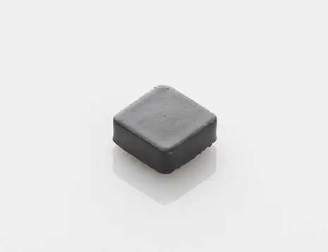
Sumida has expanded its lineup of Metal Hybrid Inductors, known as the CDMT series, which is made of two kinds of metal materials. The existing type under the CDMT series is CDMT40D20 (4.3mm x 4.3mm x H 2.1mm), CDMT40D30 (4.3mm x 4.3mm x H 3.1mm) and CDMT40D40 (4.3mm x 4.3mm x H 4.1mm) are newly added as an expansion.

RelatedPosts

Würth Elektronik Expands Nanocrystalline Cable Cores for Broadband EMI Suppression

High‑Speed Supercapacitor Balancing for AI Data Center Power Systems

Bourns Introduced Automotive TVS Diodes for Compact ESD Protection


Along with the miniaturization trend of consumer electronics devices such as smart phones and tablet PCs, longer battery life is expected by consumers. High efficiency and low loss power circuit are needed for industrial equipments such as servers and telecommunications base stations. Sumida has developed high efficiency and low loss inductors which best suit the power supply circuits for these types of products.

Through the use of a newly developed metal composite material in the mold structure, the CDMT40D30 and CDMT40D40 have outstanding electrical performance and shielding properties, they also reflect minimum loss in performance when compared with other inductors of the same size. Thus, CDMT series including the new addition is suitable for various kinds of electronic devices.

Key Features

  • Dimension:
    CDMT40D30  4.3 x 4.3 x H 3.1mm (Max.)
    CDMT40D40  4.3 x 4.3 x H 4.1mm (Max.)
  • Weight:
    CDMT40D30 0.28g (Ref.)
    CDMT40D40 0.37g (Ref.)
  • Halogen-free
  • Operating temperature range: -40°C to +125°C  (Not including coil’s self temperature rise)

Applications

  • Telecommunication base stations, servers, SSDs, and other low profile high current applications

Main Electrical Characteristics: CDMT40D30

Part Name Inductance
[within](µH) ※1
D.C.R. (mΩ)
Typ. (Max.)
Saturation Current at
20°C (A) ※2
Temperature Rise Currrent
(A) ※3
*4 *5
CDMT40D30HF-3R3NC 3.30 ±30% 23.0 (25.3)  5.0 4.30 6.60
CDMT40D30HF-4R7NC 4.70 ±30% 37.0 (40.7) 4.0  3.60 5.10
CDMT40D30HF-6R8NC 6.80 ±30% 62.0 (68.2) 3.2 2.70 3.90


Main Electrical Characteristics: CDMT40D40

Part Name Inductance
[within](µH) ※1
D.C.R. (mΩ)
Typ. (Max.)
直流重畳許容電流で20°C (A) *2 温度上昇電流
(A) *3
*4 *5
CDMT40D40HF-8R2NC 8.20 ±30% 54.0 (59.4) 3.20 2.80 3.40
CDMT40D40HF-100NC 10.0 ±30% 80.0 (88.0) 2.80 2.30 3.10
CDMT40D40HF-150NC 15.0 ±30% 107 (118) 2.50 1.95 2.80


*1 Measuring frequency at 100KHZ 0.1V
*2 Saturation current: This indicates the actual value of D.C. current when the inductance becomes 30% lower than its nominal value.
*3 Temperature rise current: The actual value of D.C. current when the temperature of coil becomes △T=40°C (Ta=20°C).
*4 Measurement condition: Irms testing was performed by a product in 25°C ambient.
*5 Measurement condition: Irms testing was performed on copper traces in 25°C ambient.
** Discharge static electricity before handling this coil. Take the static electricity measures to prevent deterioration of electric characteristics.

Production Stage
Mass Production: December 2016

Related

Recent Posts

Würth Elektronik Expands Nanocrystalline Cable Cores for Broadband EMI Suppression

23.6.2026
8

Bourns Releases Automotive Gate Driver Transformer for Isolated Power

22.6.2026
20

Knowles Expands High‑Q Ceramic Core Inductors for RF designs

19.6.2026
21

Vishay Unveils 1.5 kV IHDV High Voltage Power Inductors for EV and Industrial Converters

19.6.2026
28

DMASS: European Components Distribution Returns To Growth In Q1 2026

16.6.2026
58

German Component Distribution Market Rebounds in Q1 2026 According to FBDi

16.6.2026
39

Sumida Introduces SMD Metal Inductors for High‑Current Automotive DC/DC Converters

15.6.2026
31

Knowles Expands High Q Ceramic Core Inductors

11.6.2026
38

Vishay Extends Automotive Ferrite Beads for High‑Current EMC Noise Filtering

10.6.2026
39

Upcoming Events

Jun 30
17:00 - 18:00 CEST

PSMA Capacitor Committee Webinar: High Voltage Pulse Capacitors

Jul 14
16:00 - 17:00 CEST

EMC Design Essentials: Mastering Varistors and Common Mode Chokes

Jul 21
16:00 - 17:00 CEST

Safety by design: X and Y Interference suppression capacitors for power line filters

View Calendar

Popular Posts

  • Boost Converter Design and Calculation

    0 shares
    Share 0 Tweet 0
  • Buck Converter Design and Calculation

    0 shares
    Share 0 Tweet 0
  • LLC Resonant Converter Design and Calculation

    0 shares
    Share 0 Tweet 0
  • Flyback Converter Design and Calculation

    0 shares
    Share 0 Tweet 0
  • MLCC and Ceramic Capacitors

    0 shares
    Share 0 Tweet 0
  • Earthing Systems and IEC Classification Explained

    0 shares
    Share 0 Tweet 0
  • Nvidia Vera Rubin: Why One AI Rack Needs So Many More MLCC Capacitors

    0 shares
    Share 0 Tweet 0
  • Dual Active Bridge (DAB) Topology

    0 shares
    Share 0 Tweet 0
  • SEPIC Converter Design and Calculation

    0 shares
    Share 0 Tweet 0
  • MLCC Case Sizes Standards Explained

    0 shares
    Share 0 Tweet 0

Newsletter Subscription


Passive Components Blog

© EPCI - Leading Passive Components Educational and Information Site

  • Home
  • Privacy Policy
  • EPCI Membership & Advertisement
  • About

No Result
View All Result
  • Home
  • Knowledge Blog
  • Dossiers
  • PCNS

© EPCI - Leading Passive Components Educational and Information Site

This website uses cookies. By continuing to use this website you are giving consent to cookies being used. Visit our Privacy and Cookie Policy.
Go to mobile version