Passive Components Blog
No Result
View All Result
  • Home
  • NewsFilter
    • All
    • Aerospace & Defence
    • Antenna
    • Applications
    • Automotive
    • Capacitors
    • Circuit Protection Devices
    • electro-mechanical news
    • Filters
    • Fuses
    • Inductors
    • Industrial
    • Integrated Passives
    • inter-connect news
    • Market & Supply Chain
    • Market Insights
    • Medical
    • Modelling and Simulation
    • New Materials & Supply
    • New Technologies
    • Non-linear Passives
    • Oscillators
    • Passive Sensors News
    • Resistors
    • RF & Microwave
    • Telecommunication
    • Weekly Digest

    Advances in the Environmental Performance of Polymer Capacitors

    Vishay Releases DLA Tantalum Polymer Capacitors for Military and Aerospace

    Vishay Expanded Inductor Portfolio With More Than 2000 Stock Items 

    Paumanok Releases Capacitor Foils Market Report 2025-2030

    Modelithics Welcomes CapV as a Sponsoring MVP

    Wk 40 Electronics Supply Chain Digest

    Benefits of Tantalum Powder Stress–Strain Curve Evaluation vs Conventional Wet Test

    Electrolyte Selection and Performance in Supercapacitors

    Connector PCB Design Challenges

    Trending Tags

    • Ripple Current
    • RF
    • Leakage Current
    • Tantalum vs Ceramic
    • Snubber
    • Low ESR
    • Feedthrough
    • Derating
    • Dielectric Constant
    • New Products
    • Market Reports
  • VideoFilter
    • All
    • Antenna videos
    • Capacitor videos
    • Circuit Protection Video
    • Filter videos
    • Fuse videos
    • Inductor videos
    • Inter-Connect Video
    • Non-linear passives videos
    • Oscillator videos
    • Passive sensors videos
    • Resistor videos

    Connector PCB Design Challenges

    Efficient Power Converters: Duty Cycle vs Conduction Losses

    Ripple Steering in Coupled Inductors: SEPIC Case

    SEPIC Converter with Coupled and Uncoupled Inductors

    Coupled Inductors in SEPIC versus Flyback Converters

    Non-Linear MLCC Class II Capacitor Measurements Challenges

    Percolation Phenomenon and Reliability of Molded Power Inductors in DC/DC converters

    Root Causes and Effects of DC Bias and AC in Ceramic Capacitors

    How to Calculate the Output Capacitor for a Switching Power Supply

    Trending Tags

    • Capacitors explained
    • Inductors explained
    • Resistors explained
    • Filters explained
    • Application Video Guidelines
    • EMC
    • New Products
    • Ripple Current
    • Simulation
    • Tantalum vs Ceramic
  • Knowledge Blog
  • Suppliers
    • Who is Who
  • Events
No Result
View All Result
Passive Components Blog
No Result
View All Result

TDK introducing stacked MEGACAP Type MLCCs with high capacitance and low ESR

27.11.2019
Reading Time: 3 mins read
A A

Source: TDK news

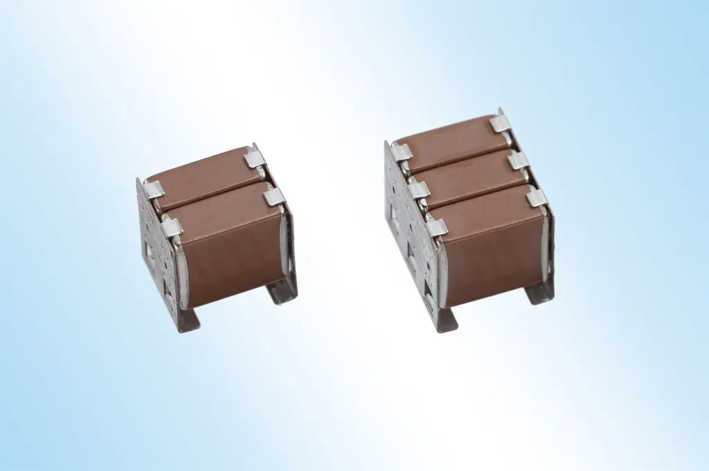
TDK Corporation has developed a new series of vertically stacked MEGACAP Type MLCCs that combine high capacitance and low ESR.

RelatedPosts

KEMET Design it Day: Capacitors and Inductors Selection Guide for Decoupling And Filtering

How to determine and measure MLCC ripple current and ESR

Degradation of ESR in Polymer Tantalum Capacitors during High Temperature Storage BEST PAPER AWARD

The new CA series offers rated voltages from 25 V to 1000 V and covers a capacitance range from 20 nF to 150 µF. The new MLCCs are available with C0G, X7T, X7S, and X7R temperature characteristics. Thanks to their high capacitance values, the new capacitors are suitable for the resonant circuits of wireless and plug-in charging systems, for example, for industrial vehicles and robots. They can also be used in smoothing and decoupling applications in industrial equipment. Production of the CA series began in April 2018. Automotive grade products will be introduced after mid-2018.

The MEGACAP Type MLCCs feature metal lead frames attached to the electrode ends of the components to protect against board flexure cracks and solder cracks from thermal shocks. The metal material of the terminal has also been optimized to lower the ESR and achieve a higher ripple current capability. In order to enable a low profile with increased capacitance, TDK has adapted its MEGACAP stack design so that the MLCC elements are stacked side by side. The vertically stacked design enables stacks with three or even more elements. Hybrid joints between the metal terminals and the MLCC are both soldered and clamped to prevent the individual MLCC elements from falling out of the lead frame at the increasingly higher reflow temperatures. The CA series will be available initially with 2x and 3x stacks. In the future the lineup will be expanded with 5x stacks. TDK offers a broad portfolio of MLCCs for a wide range of applications. TDK will continue to place a special focus on the development of technologically superior automotive grade MLCCs.

Main applications

  • Resonant circuits for wireless and plug-in charging systems
  • Smoothing and decoupling applications in industrial equipment

Main features and benefits

  • High capacitance enabled by stacked design
  • Low ESR due to optimized terminal material

Key data

Type Temperature characteristic Rated voltage [V] Capacitance [F] Stacked elements Dimensions [mm]
CAA572C0G3A203J* C0G 1000 20n 2 2x stack:6.1 x 5.6 x 6.4
3x stack:6.1 x 8.4 x 6.4
CAA572C0G3A303J* 30n 2
CAA572C0G3A443J* 44n 2
CAA572C0G3A663J* 66n 2
CAA573C0G3A993J* 99n 3
CAA572C0G2J204J* 630 200n 2
CAA573C0G2J304J* 300n 3
CAA572X7T2J105M** X7T 630 1μ 2 2x stack:6.1 x 5.0 x 6.4
3x stack:6.1 x 7.5 x 6.4
CAA573X7T2J155M** 1.5μ 3
CAA572X7T2W225M** 450 2.2μ 2
CAA573X7T2W335M** 3.3μ 3
CAA572X7S2A336M** X7S 100 33μ 2
CAA573X7S2A476M** 47μ 3
CAA572X7R1V107M** X7R 35 100μ 2 2x stack:6.4 x 5.0 x 6.8
3x stack:6.4 x 7.5 x 6.8
CAA573X7R1V157M** 150μ 3
CAA572X7R1E107M** 25 100μ 2
CAA573X7R1E157M** 150μ 3

*Production begin: April 2018 (AEC-Q200 qualified products after mid-2018)
**Production begin: July 2018 and onward

Related

Recent Posts

Advances in the Environmental Performance of Polymer Capacitors

8.10.2025
2

Vishay Releases DLA Tantalum Polymer Capacitors for Military and Aerospace

8.10.2025
3

Paumanok Releases Capacitor Foils Market Report 2025-2030

7.10.2025
9

Modelithics Welcomes CapV as a Sponsoring MVP

7.10.2025
2

Benefits of Tantalum Powder Stress–Strain Curve Evaluation vs Conventional Wet Test

3.10.2025
20

Electrolyte Selection and Performance in Supercapacitors

3.10.2025
16

Researchers Demonstrated High Energy Ceramic Capacitors Stable in Wide Temperature Range

2.10.2025
24

Stackpole Offers High Voltage Plate Resistors up to 40KV

2.10.2025
18

How to Manage Supercapacitors Leakage Current and Self Discharge 

1.10.2025
39

Qualification of Commercial Supercapacitors for Space Applications

1.10.2025
38

Upcoming Events

Oct 14
16:00 - 17:00 CEST

Smart Sensors, Smarter AI: Building Reliable Edge Systems

Oct 17
12:00 - 14:00 EDT

External Visual Inspection per MIL-STD-883 TM 2009

Oct 20
October 20 - October 23

Digital WE Days 2025 – Virtual Conference

Oct 21
October 21 @ 12:00 - October 23 @ 14:15 EDT

Space and Military Standards for Hybrids and RF Microwave Modules

Oct 28
8:00 - 15:00 CET

Power Up Your Design: SN6507 and the Ready-to-Use Development Kit

View Calendar

Popular Posts

  • Buck Converter Design and Calculation

    0 shares
    Share 0 Tweet 0
  • Boost Converter Design and Calculation

    0 shares
    Share 0 Tweet 0
  • Flyback Converter Design and Calculation

    0 shares
    Share 0 Tweet 0
  • LLC Resonant Converter Design and Calculation

    0 shares
    Share 0 Tweet 0
  • SEPIC Converter Design and Calculation

    0 shares
    Share 0 Tweet 0
  • Ripple Current and its Effects on the Performance of Capacitors

    3 shares
    Share 3 Tweet 0
  • Dual Active Bridge (DAB) Topology Explained

    0 shares
    Share 0 Tweet 0
  • What is a Dielectric Constant and DF of Plastic Materials?

    4 shares
    Share 4 Tweet 0
  • Flying Capacitors Explained

    0 shares
    Share 0 Tweet 0
  • MLCC and Ceramic Capacitors

    0 shares
    Share 0 Tweet 0

Newsletter Subscription


Passive Components Blog

© EPCI - Leading Passive Components Educational and Information Site

  • Home
  • Privacy Policy
  • EPCI Membership & Advertisement
  • About

No Result
View All Result
  • Home
  • Knowledge Blog
  • Premium Suppliers

© EPCI - Leading Passive Components Educational and Information Site

This website uses cookies. By continuing to use this website you are giving consent to cookies being used. Visit our Privacy and Cookie Policy.
Go to mobile version