Passive Components Blog
No Result
View All Result
  • Home
  • NewsFilter
    • All
    • Aerospace & Defence
    • Antenna
    • Applications
    • Automotive
    • Capacitors
    • Circuit Protection Devices
    • electro-mechanical news
    • Filters
    • Fuses
    • Inductors
    • Industrial
    • Integrated Passives
    • inter-connect news
    • Market & Supply Chain
    • Market Insights
    • Medical
    • Modelling and Simulation
    • New Materials & Supply
    • New Technologies
    • Non-linear Passives
    • Oscillators
    • Passive Sensors News
    • Resistors
    • RF & Microwave
    • Telecommunication
    • Weekly Digest

    October 2025 Interconnect, Passives and Electromechanical Components Market Insights

    Exxelia 4-Terminal Safety Capacitors Compliant with NF F 62-102 Railway Standard

    Wk 43 Electronics Supply Chain Digest

    Samsung Releases Automotive Molded 2220 1kV C0G MLCC

    How to Select Ferrite Bead for Filtering in Buck Boost Converter

    VINATech Offers Smallest 100µF Al-Hybrid Capacitor

    Vishay Unveils SMD 1200V PTC Thermistors in Compact Size

    Power Inductors Future: Minimal Losses and Compact Designs

    Bourns Unveils Automotive 3 Watt Gate Driver Transformer

    Trending Tags

    • Ripple Current
    • RF
    • Leakage Current
    • Tantalum vs Ceramic
    • Snubber
    • Low ESR
    • Feedthrough
    • Derating
    • Dielectric Constant
    • New Products
    • Market Reports
  • VideoFilter
    • All
    • Antenna videos
    • Capacitor videos
    • Circuit Protection Video
    • Filter videos
    • Fuse videos
    • Inductor videos
    • Inter-Connect Video
    • Non-linear passives videos
    • Oscillator videos
    • Passive sensors videos
    • Resistor videos

    How to Select Ferrite Bead for Filtering in Buck Boost Converter

    Power Inductors Future: Minimal Losses and Compact Designs

    Percolation Phenomenon: Degradation of Molded Power Inductors in DC/DC Converters

    Connector PCB Design Challenges

    Efficient Power Converters: Duty Cycle vs Conduction Losses

    Ripple Steering in Coupled Inductors: SEPIC Case

    SEPIC Converter with Coupled and Uncoupled Inductors

    Coupled Inductors in SEPIC versus Flyback Converters

    Non-Linear MLCC Class II Capacitor Measurements Challenges

    Trending Tags

    • Capacitors explained
    • Inductors explained
    • Resistors explained
    • Filters explained
    • Application Video Guidelines
    • EMC
    • New Products
    • Ripple Current
    • Simulation
    • Tantalum vs Ceramic
  • Knowledge Blog
  • Suppliers
    • Who is Who
  • PCNS
    • PCNS 2025
    • PCNS 2023
    • PCNS 2021
    • PCNS 2019
    • PCNS 2017
  • Events
No Result
View All Result
Passive Components Blog
No Result
View All Result

Test Explanations: Corrosion

14.9.2021
Reading Time: 3 mins read
A A

As noted previously, the environmental exposures for non-noble (tin) and noble (gold) plated contacts are different. The dominant degradation mechanism for tin connectors is fretting corrosion, a build-up of oxide debris at the contact interface due to small scale motions (tens of microns). The oxidation of tin is a given and the degradation process is dominated by the mechanical stability of the contact interface with respect to inhibiting fretting motions. Tin corrosion exposures are predominantly temperature-humidity related and there is no generally accepted correlation between such exposures and field performance.

The situation with noble metal finishes, in particular gold over nickel, is very different. There were a number of investigations into the environmental stability of gold contact finishes in the ‘70s and a significant amount of data relating test environments to field performance was developed. The details of these studies are outside the scope, but suffice it to say that there are two test environments that are generally accepted as indicative of field performance. As shown in Table 2.9, taken from EIA 364 TP 65 they are:

RelatedPosts

Polymer Materials and Processing

What is RF Connector

Connector Materials and Processes

Tab. 2.9: Mixed flowing gas exposure parameters

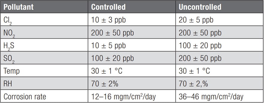
While other test environments are specified, they have in common the important pollutants, Cl2, NO2, H2S and SO2, and the low level of pollutant concentrations, parts per billion and the temperature and humidity levels.

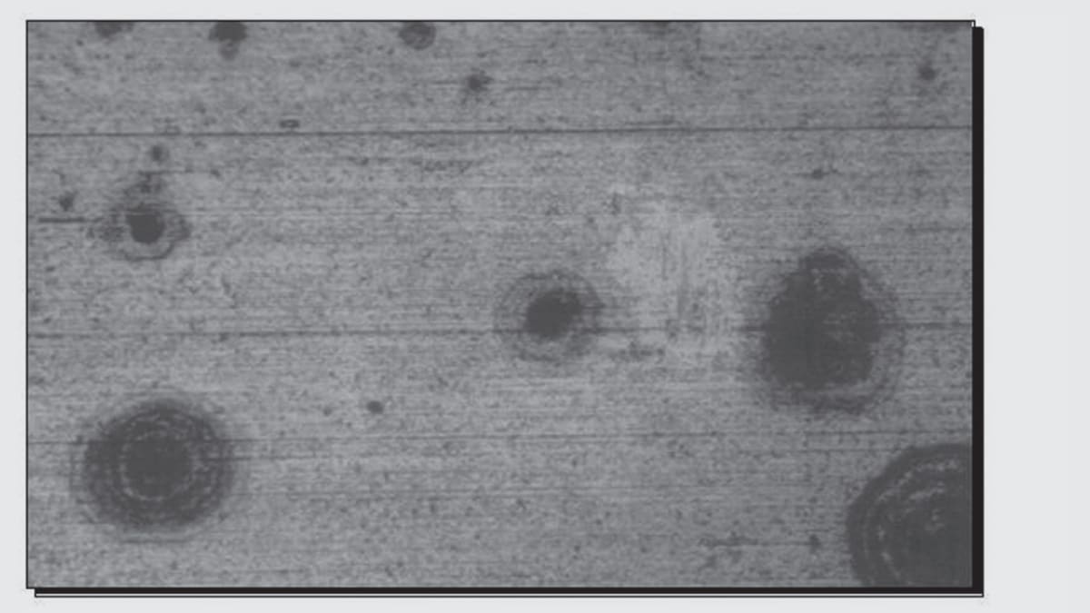
Some of the major findings about noble metal corrosion in mixed flowing gas environments are suggested in Figure 2.120 and 2.121.

Fig. 2.120: Pore corrosion and corrosion migration from pore sites

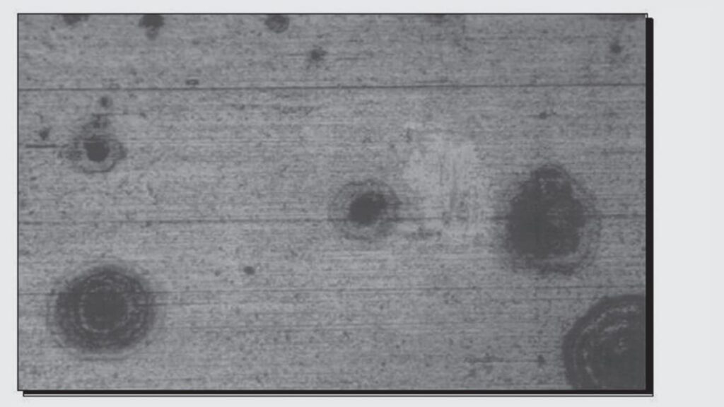
First, Figure 2.120 illustrates pore corrosion and the migration of corrosion products from the pore sites over the contact surface, the rings around the pore sites. The corrosion source, in all cases, is the copper alloy of the contact spring. The corrosion products that are migrating are identified in Figure 2.121. The X-ray maps shown in Figure 2.121 show that the

Fig. 2.121: X-ray maps identifying corrosion product migration from pore sites

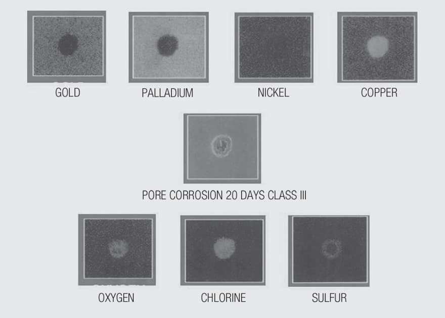
contact finish under test was a gold flash over nickel over copper alloy. The pore site in this case originated at the copper alloy as indicated by the intensity of the copper signal at the upper right in the figure. The corrosion products, the lower row of X-ray maps consisted of copper, oxygen, chlorine and sulfur. The corrosion synergy between chlorine and sulfur distinguishes mild from harsh environments. Note the difference in corrosion rates between the controlled and uncontrolled environments and the chlorine and sulfur concentrations in Table 2.9. The corrosion rates are, in fact, used to validate the exposure by measuring the sample weight gain. There are acceleration factors for these two environments with a two day exposure to the test environment being equivalent to a year of exposure in the field environment.

Related

Source: Wurth elektronik

Recent Posts

Connector PCB Design Challenges

3.10.2025
48

Non-Magnetic Interconnects

23.4.2025
27

10 Tips for Ensuring Reliability of Discrete Wire Assemblies

20.2.2025
56

Polymer Materials and Processing

11.8.2025
64

Basic PCB Technology Overview

1.7.2025
26

What is RF Connector

17.12.2024
15

Creepage and Clearance of Connector

25.7.2025
24

Microwave Multi Line Connectors Mounting and Handling Precautions

11.8.2025
3

BASIC PCB Design Rules – Layout

1.7.2025
37

MEMR RF Relay for Space Compact Redundancy Ring

17.12.2024
4

Upcoming Events

Oct 30
11:00 - 12:00 CET

Space Ceramic Capacitors with Flexible Testing

Nov 4
10:00 - 11:00 PST

Design and Stability Analysis of GaN Power Amplifiers using Advanced Simulation Tools

Nov 4
November 4 @ 12:00 - November 6 @ 14:15 EST

Wirebond Materials, Processes, Reliability and Testing

View Calendar

Popular Posts

  • Buck Converter Design and Calculation

    0 shares
    Share 0 Tweet 0
  • Boost Converter Design and Calculation

    0 shares
    Share 0 Tweet 0
  • Flyback Converter Design and Calculation

    0 shares
    Share 0 Tweet 0
  • LLC Resonant Converter Design and Calculation

    0 shares
    Share 0 Tweet 0
  • Ripple Current and its Effects on the Performance of Capacitors

    3 shares
    Share 3 Tweet 0
  • SEPIC Converter Design and Calculation

    0 shares
    Share 0 Tweet 0
  • What is a Dielectric Constant and DF of Plastic Materials?

    4 shares
    Share 4 Tweet 0
  • Dual Active Bridge (DAB) Topology

    0 shares
    Share 0 Tweet 0
  • MLCC and Ceramic Capacitors

    0 shares
    Share 0 Tweet 0
  • Flying Capacitors

    0 shares
    Share 0 Tweet 0

Newsletter Subscription


Passive Components Blog

© EPCI - Leading Passive Components Educational and Information Site

  • Home
  • Privacy Policy
  • EPCI Membership & Advertisement
  • About

No Result
View All Result
  • Home
  • Knowledge Blog
  • PCNS

© EPCI - Leading Passive Components Educational and Information Site

This website uses cookies. By continuing to use this website you are giving consent to cookies being used. Visit our Privacy and Cookie Policy.
Go to mobile version