This article based on expanded Knowles Precision Devices blog elaborates on importance of safety capacitors and its benefits especially in power electronic applications. It also compares film and ceramic capacitors selection guide.
Key Takeaways
- Safety capacitors mitigate transient voltages and interference in electrical circuits, crucial in high-voltage applications.
- Common applications include modems, automotive electronics, and power supplies, enhancing user safety and device reliability.
- Class-X and Class-Y capacitors serve different purposes, with X handling line-to-line protection and Y focusing on line-to-ground safety.
- Choosing between film and ceramic safety capacitors depends on factors like voltage rating, size, and environmental conditions.
- Film capacitors excel in high-voltage applications, while ceramic capacitors are compact and cost-effective for lower power devices.
Safety capacitors are designed to mitigate the effects of transient voltages and interference in electrical and electronic circuits, especially high-voltage applications, ensuring their safe operation.
Even everyday devices need safety capacitors: modems and other telecoms equipment, AC-DC power supplies, power distribution switchgear, and electric vehicles (EVs) and other automotive applications.
The Role of the Safety Capacitor
In a circuit, safety capacitors used on AC lines filter high-frequency electromagnetic interference (EMI), or undesirable electromagnetic emissions or disturbances generated either by electronic devices or natural sources in the environment that can interfere with the proper functioning of other nearby devices or systems. This is known as EMI filtering, with the filter providing a safe path for noise while maintaining electrical isolation and safety.
When placed in combination with a series of inductors or resistors, safety capacitors form low-pass filters that attenuate the high-frequency signals (EMI) and allow the lower-frequency power signals to pass. This is the classic EMI filter setup—attenuating unwanted noise above a cutoff frequency. As more electronic devices enter the market, EMI filtering becomes even more crucial as there is an increased likelihood that EMI could cause a device to malfunction, crash, or fail.
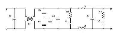
In power electronics specifically, EMI filters take the form of power line filters that protect the line from upstream noise. While this list may differ depending on system requirements, the core components of a power line filter include:
- A common-mode filter circuit with two or more line-to-chassis capacitors and a common-mode inductor
- A differential mode (DM) filter circuit with at least one pair of series inductors and one line-to-line capacitor
- Compensation networks to adjust the filter’s quality (Q) factor and adapt the output impedance as needed
- Transient voltage suppression device(s) to defend against surges
Figure 1. shows an EMI filter structure that could be useful for single-phase AC applications or for DC power inputs.
Where Safety Capacitors are Used
To ensure safe operations and compliance with electrical safety standards, you’ll find safety capacitors in nearly every electronic device developed today – from industrial motor drives and HVAC systems to consumer appliances to medical devices, telecommunications equipment, and automotive electronics. For many of these applications, safety capacitors are crucial components that ensure user safety and reliable performance.
Classes of Safety Capacitors
In general, there are two classes of capacitors, Class-X and Class-Y, that are both used to minimize EMI in different applications.
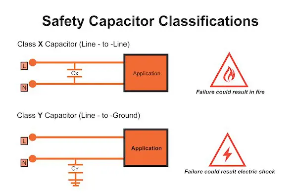
- X Capacitors: Class-X capacitors, also known as “across-the-line capacitors,” are used between the wires carrying the incoming AC current. These offer line-to-line protection, which means that if there is a failure, a short may occur, but there is no risk of shock. An X capacitor failure usually causes a fuse or circuit breaker to open.
- Y Capacitors: Class-Y capacitors, also known as “line-to-ground capacitors” or “line bypass capacitors,” offer line-to-ground protection, which generally means that if a failure with the ground occurs, there is a risk for shock. However, Class-Y safety capacitors must meet rigorous specifications, minimizing the chance of electric shock.
- X/Y Capacitors: Some safety capacitors handily combine classes, for example, X1/Y2. This simply means that the capacitor can be used as an X1 capacitor in an across-the-line application or as a Y2 capacitor in the line-to-ground portion of the circuit.
Safety Capacitor Subclasses
As mentioned, both X and Y capacitors are further broken into the following subclasses according to their pulse voltage withstand capability and rated voltage (more details in Table 1):
- X Capacitor Subclasses:
- X1: For higher surge levels (≥2.5 kV and ≤4 kV)
- X2: Most common in consumer electronics (≤2.5 kV)
- X3: For ≤1.2 kV, less common
- X Capacitor Subclasses:
- Y1: For higher insulation and impulse voltage (>500 VAC, up to 8 kV)
- Y2: Common for 250 VAC operation
- Y3/Y4: Lower ratings, used in less critical applications
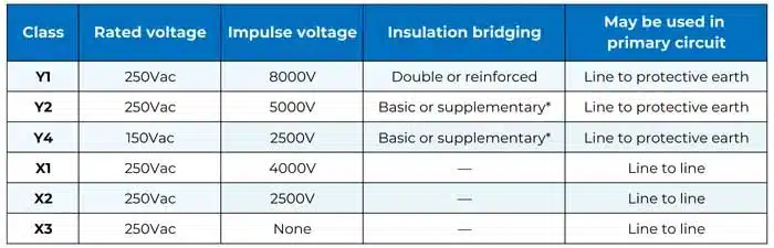
*2x Y2 or Y4 rated may bridge double or reinforced insulation when used in series
By understanding the differences between the different capacitor classes and subclasses, you can optimize product development while ensuring user safety, product compliance, and reliable circuit performance.
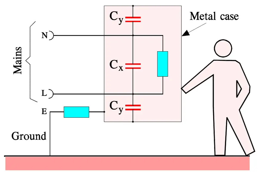
The X and Y safety capacitors are connected to the mains according to Figure 3. There they also serve another important purpose. Transients strike namely every live mains relatively often. They may come from the ”outside” but may also be generated by our own equipment.
Between 80 and 90 % of all transients from the mains last between 1 and 10 μs, are higher than 1000 V, have voltage rise times of 200 to 2000 V/μs and are occurring at least 10 times a day. We realize that their damage must be eliminated. It is done by the X-capacitors which thus are connected between the lines of the mains.
The Y-capacitors represent another type of transient suppression. They are connected between either of the power lines and the grounded cover of electric equipment. Here we require an extra high safety against short-circuits in order to prevent the equipment being put under tension and thus causing serious personal injuries. Besides, the Y-capacitor shall have a limited capacitance in order not to bring about harmfully high currents through the human body in case of a possible open circuit in the ground wire (see Figure 3.).
In order to verify that the X- and Y-capacitors really can withstand occurring transients they must pass the following three tests without remarks.
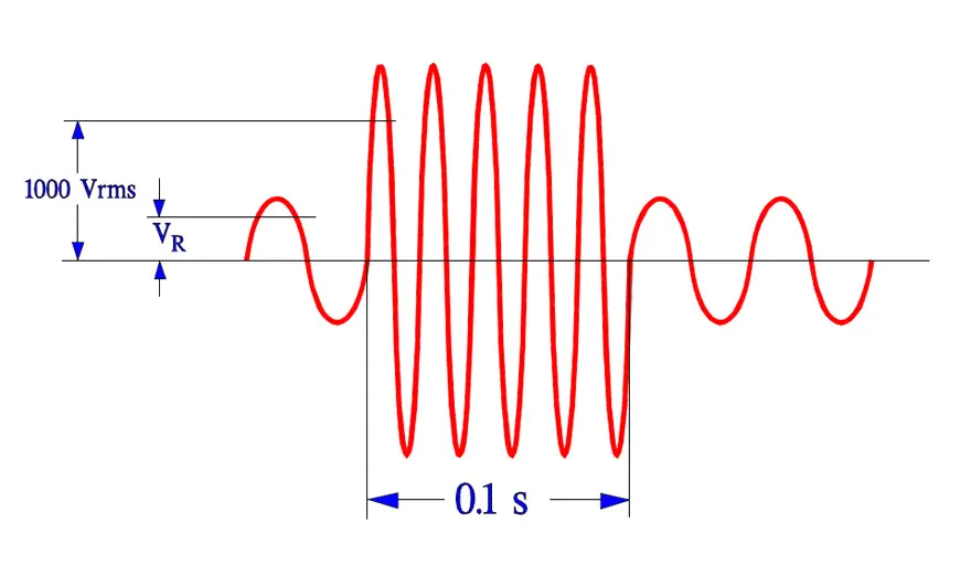
- Life test according to IEC 384-14, 1000 hrs at Tuc and 1.25xVR + 1000 Vrms every hour for 0.1 s.
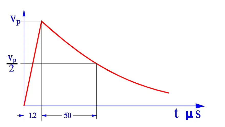
- Surge voltage test according to 384-14. Three pulses of Vp = 2.5 to 5 kV depending on capacitor type.
- Charge and discharge test according to IEC 384-14. 10 000 pulses at 100 V/s and 2xVR.
X- and Y-capacitors must have an approval by national inspection authorities in order to be used in respective countries. All European check routines are collected in one standard, EN 13 24 00. The USA standards are collected under UL and the Canadian under CSA.
General Considerations for Selecting a Safety Capacitor Technology
When comparing whether to use a multilayer ceramic capacitor (MLCC) or film capacitor for your safety capacitor, you need to consider the capacitor’s construction, performance characteristics, and suitability for specific safety roles as well as the capacitor’s:
- Temperature range
- Size constraints
- Voltage rating
- Capacitance value
- Cost
In addition to electrical parameters, the physical package strongly influences creepage and clearance on the PCB. Leaded film X capacitors inherently provide a defined lead spacing and body geometry that helps meet mains creepage/clearance requirements, while SMD safety MLCCs can simplify routing in compact SMPS layouts but require careful board design and cleanliness to maintain adequate surface creepage distances and insulation.
Let’s further explore the characteristics of both MLCCs and film capacitors.
Ceramic Capacitors
In general, for line-to-ground configurations, or Class Y capacitors, safety requirements dictate that failure must not result in a conductive path that could pose a shock hazard. MLCCs, when properly rated, can meet these requirements. Some benefits of using MLCCs include the following:
- Compact size, allowing for high capacitance in a small footprint, which is ideal for space-constrained designs
- Cost-effective manufacturing makes ceramics attractive for high-volume, cost-sensitive projects
- Low equivalent series resistance (ESR) and equivalent series inductance (ESL) support effective high-frequency EMI suppression
Some challenges with using ceramic include that ceramic generally has a lower voltage rating than film, which can limit its use in high-power designs. Additionally, while some MLCCs can withstand high temperatures and humidity, others may be susceptible to performance drift under environmental stress, which can impact long-term reliability.
As a result, ceramic is well suited for Y1 and Y2 safety capacitors, especially those used in appliances, chargers, or compact consumer electronics where space and cost are driving factors.
In recent years, several manufacturers have expanded their enhanced safety‑certified SMD MLCC portfolios, introducing X1/Y2 and other specialized series with improved surge performance and wider capacitance ranges. This trend is making ceramic technology a practical alternative in some safety‑critical positions that were historically implemented only with film capacitors, especially in compact power supplies and on‑board converters in automotive and industrial systems.
Film Capacitors
Film capacitors are most commonly used in Class X applications where they are installed across the AC line. Therefore, these capacitors must be able to withstand large voltage surges and recover from a dielectric breakdown with only a small reduction in capacitance. Advantages of using a film capacitor include the following:
- High voltage tolerance that enables reliable performance
- Self-healing properties that allow the capacitor to recover from small dielectric failures without catastrophic failure
- Excellent stability over time and varying environmental conditions to ensure long service life and consistent safety compliance
Since film capacitors are typically larger in size, it may be challenging to use these capacitors in densely packed assemblies. Film capacitors also typically cost more than ceramic options, which may be a consideration for cost-sensitive markets.
As a result, film is typically a good fit for X1 and X2 safety capacitors used in industrial equipment, power supplies, or any design that must withstand line surges and operate over extended periods.
Ceramic vs. Film Safety Capacitors in Practice
When selecting safety capacitors for power electronics, the first decision is often whether the part will operate in a Class X (line‑to‑line) or Class Y (line‑to‑ground) role and then which technology – ceramic MLCC or film – best fits that role. In many designs this mapping is quite clear: film is typically favored for X1/X2 across‑the‑line positions, while safety‑rated MLCCs are widely used for Y1/Y2 line‑to‑ground positions in compact, cost‑sensitive equipment.
Film safety capacitors provide high surge capability, excellent long‑term stability, and self‑healing behavior that is ideal for absorbing repetitive mains transients without catastrophic failure. These properties make them the default choice in demanding industrial, appliance, and power‑supply Class X1/X2 locations, even though their physical size and cost are higher than ceramic.
Safety‑certified MLCCs, on the other hand, offer a very compact footprint, low ESR/ESL for high‑frequency EMI attenuation, and attractive cost for high‑volume production. They are therefore commonly selected for Y1/Y2 roles in chargers, adapters, household appliances, IT equipment, and on‑board low‑power supplies where board space is limited and the required surge levels are lower than in heavy industrial mains filters.
The practical result is that many power‑supply input stages use a mixed technology approach: a film X2 capacitor across the line to handle differential‑mode surges and energy, combined with one or more Y2 MLCCs from line and neutral to chassis to control common‑mode noise within a tight layout envelope.
| Aspect | MLCC (ceramic) – safety use | Film – safety use |
|---|---|---|
| Typical class | Y1/Y2 in compact equipment | X1/X2 across line |
| Strength | Small size, low ESR/ESL, cost | Surge capability, self‑healing, stability |
| Limits | Lower Vr, env. sensitivity | Larger size, higher cost |
Example: Safety Capacitors in an AC‑DC Power Supply
A typical off‑line AC‑DC power supply input stage illustrates how different safety capacitor technologies are combined in practice. An X2 film capacitor is placed directly across the mains to handle differential‑mode interference and repetitive line transients, while a pair of Y2 safety MLCCs connects line and neutral to the protective earth or chassis to control common‑mode noise within tight creepage and clearance constraints on the PCB.
In higher‑power or harsher industrial designs, designers may upgrade to X1 and Y1 classes and select film capacitors even for some line‑to‑ground positions where exceptional surge robustness and lifetime are required. For compact chargers, adapters, and consumer equipment, the emphasis shifts toward Y2 safety MLCCs to minimize volume and cost while still meeting regulatory EMI and safety requirements.
MP or MK Film Capacitors?
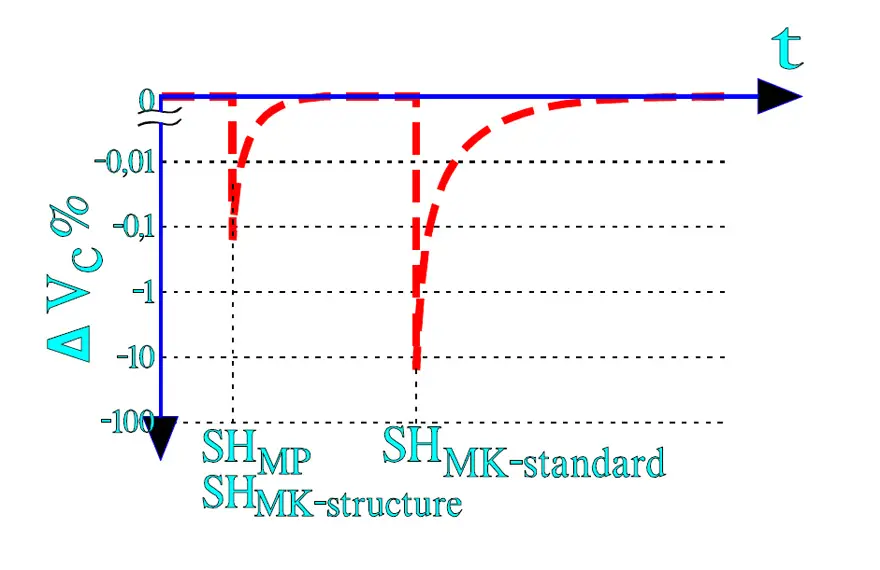
In X- and Y-capacitor applications we have to count on self-healing breakdowns. The voltage drop caused by a self-healing depends on the energy that is consumed in order to evaporate dielectric and metallizing. Here MPs with their zinc metallizing have been superior to plastic film capacitors which by tradition have had an Al metallization whose evaporation process requires several times higher energy than Zn. Nowadays, however, plastic film capacitors (MK) are brought on the market with metallization alloys based on the advantageous characteristics of zinc but without its tendency towards aqueous corrosion.
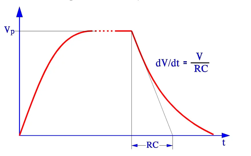
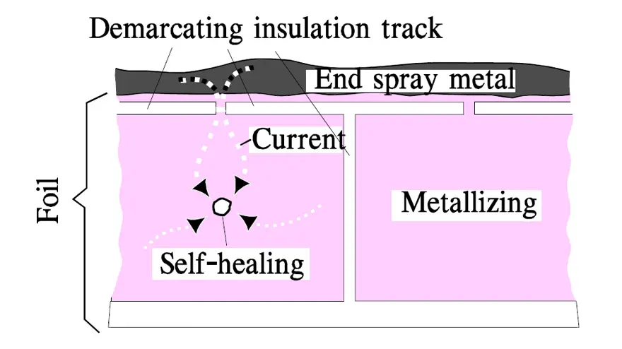
Further on there exist special designs of metallized plastic films where a segmented metallization is used, sometimes called a structure metallization. The surface is divided in mutually demarcated elements that are within reach of the charging current via narrow gates. At a self-healing the surge current burns them off. See example in Figure 7. and 8. below. The surface element is isolated and the discharge current from other elements is cut off as well as the beginning voltage drop. One gets approximately the same energy limitation as by a self-healing in an MP capacitor, especially if the structure metallization is combined with choices of modern metallizing alloys. Following Figure 7. shows typical self-healing effects on the voltage drop over a capacitor.
The metallized plastic films (MK) that hitherto have been used are polyester (MKT) and polypropylene (MKP). The latter need not be structure metallized due to its excellent self-healing chemistry. Combined with very thin ZnAl metallizing the design gets the same characteristics as structure metallized MK. In addition its high frequency characteristics are superior to those of other films.
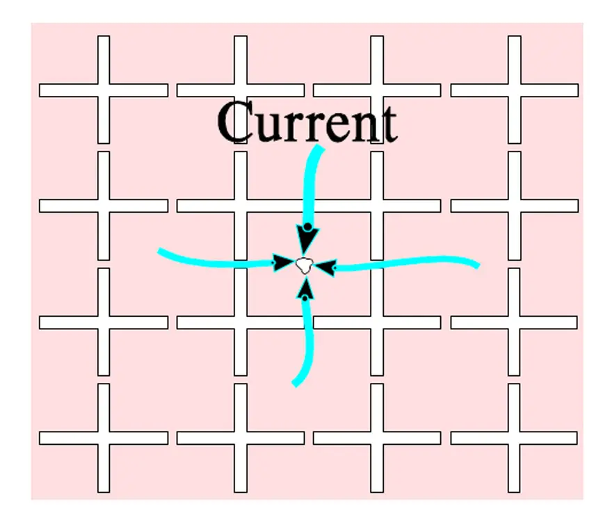
The metallizing in structured surface elements makes great demands for the design. Even if cost-effective methods are developed they involve a certain rise in prices. The simplified segmented metallization in Figure 8. actually consists of a grid-like pattern that is distributed over the whole surface as shown in Figure 9.
Another, and very interesting, structure metallization consists of metallized circular surfaces on top of a thin, high surface resistivity metallizing that covers the total surface. The weak circular joints serve together with the thin underlying metallization as fusing elements. The fusing function is favored by a metallization of zinc or low energy alloy.

Every self-healing reduces the capacitance correspondingly to the surface reduction. The author’s opinion is that the MP capacitor still is superior to structure metallized MK types. But, of course, both types meet current standards and safety requirements.
Selecting the Right Safety Capacitor for Your Design
The choice between using ceramic or film for your safety capacitors requires a clear understanding of the capacitor’s role, requirements, and environmental operating conditions. Ceramic capacitors offer compactness and cost advantages, making them well suited for many Class Y roles. Film capacitors, with their robust voltage handling and reliability, are typically the preferred choice for demanding Class X applications.
FAQ: Safety Capacitors
Safety capacitors are specialized components designed to suppress transient voltages and electromagnetic interference (EMI) in power circuits. They are crucial for ensuring user safety, compliance with international standards, and reliable operation of devices such as power supplies, automotive electronics, and telecom equipment.
Class X capacitors (across-the-line) provide line-to-line protection, typically preventing surges from damaging equipment. Class Y capacitors (line-to-ground) protect against shock hazards by ensuring safe grounding. Some capacitors combine both functions, such as X1/Y2 types.
Ceramic capacitors (MLCCs) are compact, cost-effective, and ideal for Class Y applications in consumer electronics. Film capacitors are larger but offer higher voltage tolerance, self-healing properties, and long-term stability, making them suitable for Class X applications in industrial and high-power systems.
Safety capacitors must comply with IEC, EN, UL, and CSA standards. They undergo rigorous life, surge, and charge/discharge testing to ensure reliability under real-world conditions.
How-to: Select the Right Safety Capacitor
- Define the application
Identify whether the capacitor will be used for line-to-line (Class X) or line-to-ground (Class Y) protection. This determines the safety class required.
- Check voltage and surge requirements
Review the rated voltage and surge withstand capability dictated by the safety class and the mains environment. For example, X1 capacitors handle up to 4 kV surges, X2 types are common up to 2.5 kV, while Y1 and Y2 capacitors are selected according to their insulation level and impulse voltage capability for line‑to‑ground positions.
- Choose capacitor technology
For across‑the‑line Class X1/X2 positions that must absorb large surge energy and operate for many years on the mains, film capacitors are usually preferred because of their high surge capability, self‑healing dielectric, and stable capacitance over life. For Class Y1/Y2 line‑to‑ground roles in space‑constrained or cost‑sensitive designs, safety‑rated MLCCs are often chosen thanks to their compact size, low ESR/ESL, and favorable cost structure.
- Verify compliance with standards
Ensure the chosen capacitor meets IEC, EN, UL, or CSA certifications and passes life, surge, and discharge tests for safety approval.
- Optimize for environment and cost
Consider operating temperature, humidity, pollution degree, enclosure class, and expected service life in addition to board space and budget. Film safety capacitors tend to be more robust in harsh industrial or outdoor environments, while ceramic safety MLCCs are well suited for indoor consumer and IT equipment where space is limited and the environment is better controlled.