Passive Components Blog
No Result
View All Result
  • Home
  • NewsFilter
    • All
    • Aerospace & Defence
    • Antenna
    • Applications
    • Automotive
    • Capacitors
    • Circuit Protection Devices
    • electro-mechanical news
    • Filters
    • Fuses
    • Inductors
    • Industrial
    • Integrated Passives
    • inter-connect news
    • Market & Supply Chain
    • Market Insights
    • Medical
    • Modelling and Simulation
    • New Materials & Supply
    • New Technologies
    • Non-linear Passives
    • Oscillators
    • Passive Sensors News
    • Resistors
    • RF & Microwave
    • Telecommunication
    • Weekly Digest

    Nvidia Vera Rubin: Why One AI Rack Needs So Many More MLCC Capacitors

    Stackpole Introduces 1400A Busbar Shunt Resistors

    Tecate Unveils High‑temp 105C Supercapacitors for Harsh‑Environment Designs

    Bourns Expands 1000V High‑Power Fuses for Semiconductor and Battery Protection

    Passive Components in 2026: From Invisible Commodity to Design Parameter

    Bourns Introduces High Current Chip Ferrite Beads for Dense Power Rails

    Wk 22 Electronics Supply Chain Digest

    Vishay Releases High‑Current Radial Inductors up to 209 A

    May 2026 Interconnect, Passives and Electromechanical Components Market Insights

    Trending Tags

    • Ripple Current
    • RF
    • Leakage Current
    • Tantalum vs Ceramic
    • Snubber
    • Low ESR
    • Feedthrough
    • Derating
    • Dielectric Constant
    • New Products
    • Market Reports
  • VideoFilter
    • All
    • Antenna videos
    • Capacitor videos
    • Circuit Protection Video
    • Filter videos
    • Fuse videos
    • Inductor videos
    • Inter-Connect Video
    • Non-linear passives videos
    • Oscillator videos
    • Passive sensors videos
    • Resistor videos

    Current Sense Transformer Datasheet and Design‑in Guide

    Designing a USB Type‑C Flyback Planar Transformer with Frenetic’s Planar Tool

    Magnetics Design in High‑Frequency GaN Converters

    Qi2 Wireless Charging: Inductors, Capacitors and EMC Filters

    Two‑capacitor paradox explained for engineers

    Capacitances of Nonlinear MLCCs: What Datasheets Don’t Tell You

    Tapped Inductor Buck Converter Fundamentals

    Planar vs Conventional Transformer: When it Make Sense

    Modeling Fringing Field Losses in Inductors & Transformers

    Trending Tags

    • Capacitors explained
    • Inductors explained
    • Resistors explained
    • Filters explained
    • Application Video Guidelines
    • EMC
    • New Products
    • Ripple Current
    • Simulation
    • Tantalum vs Ceramic
  • Knowledge Blog
  • DossiersNew
  • Suppliers
    • Who is Who
  • PCNS
    • PCNS 2025
    • PCNS 2023
    • PCNS 2021
    • PCNS 2019
    • PCNS 2017
  • Events
No Result
View All Result
Passive Components Blog
No Result
View All Result

Influence of Tantalum Capacitor Pellets Size on Stability During Oxide Film Formation

23.2.2026
Reading Time: 6 mins read
A A

This article by Dr. V. Azbel, an Independent consultant on tantalum capacitors investigates influence of the size of sintered tantalum pellets on stability during the tantalum oxide film formation.

This study examines the impact of geometric dimensions on the mechanical properties and stability of sintered porous tantalum pellets during oxide film formation.

RelatedPosts

Mechanical SSC Testing as a Structural Diagnostic Tool for Tantalum Capacitor Anodes

Using Stress–Strain Curves to Diagnose Tantalum Powders for Capacitors

How a Digital Structural Twin Can Predict Tantalum Capacitor Reliability

All technological parameters, including powder grade, pressing density, sintering temperature and time, shrinkage, and oxygen content, were kept constant, with the sole variable being pellet size. The findings indicate that yield strength and heat dissipation, both influenced by neck size, are critical factors in determining stability during formation.

Introduction

Sintered porous tantalum pellets, produced from 20 kCV/g powder with a green density of 5.5 g/cm³ and sintered at 1620°C for 20 minutes, are utilized in the manufacturing of tantalum capacitor anodes. Given identical sintering conditions, shrinkage was uniform across samples.

The morphology of the porous structure significantly affects the pellets’ behavior during oxide film formation. Stress-strain curve characteristics were employed as numerical indicators. Previous research has shown that yield strength, Young’s modulus (k₁), and the hardening coefficient (k₂) are contingent upon pressing and sintering conditions. In this study, all parameters and pellet shapes were consistent, allowing for an exploration of the effects of pellet size on thermal conductivity, internal stresses, and stability during formation.

Experimental

In an experimental study, tantalum powder of uniform grade, with a specific gravity of 20 kCV/g, was used to create pellets under identical processing conditions, including temperature, time, density, shrinkage, and oxygen content.

The pellets were categorized into two sizes: Pellet A, which had a smaller diameter and height, and Pellet B, which was larger in dimensions. After sintering, both pellets were subjected to electrolytic formation at the same voltages using two different electrolytes: 0.01% H₃PO₄ and a mixture of 50% glycol with 0.05% H₃PO₄. These electrolytes differ in conductivity, which affects the electrolysis rate and heat dissipation, with the formation current normalized to mass in amperes per gram.

Processing Conditions: Pellets A and B were processed under identical conditions (temperature, time, density, shrinkage, oxygen content).

Samples: 

  • Pellet A: Smaller diameter and height.
  • Pellet B: Larger dimensions.
Pellet SizePellet APellet B
diameter [mm]3.14.83
height [mm]110

Post-sintering, the pellets underwent electrolytic formation at identical voltages in two electrolytes:

  • 0.01% H₃PO₄
  • 50% glycol + 0.05% H₃PO₄

These electrolytes vary in conductivity, influencing the electrolysis rate and heat dissipation. The formation current was normalized to mass (A/g).

Results

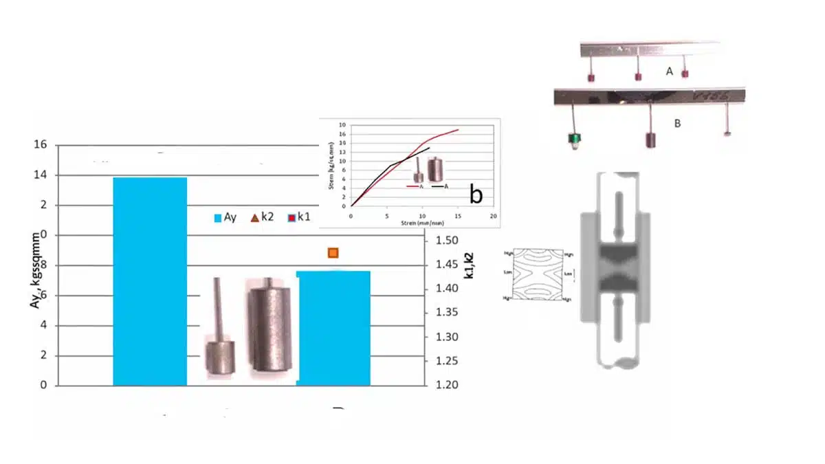
The results, as depicted in Figure 1, include combined data on mechanical parameters, stress-strain diagrams, and stress distribution under compression for both pellets.

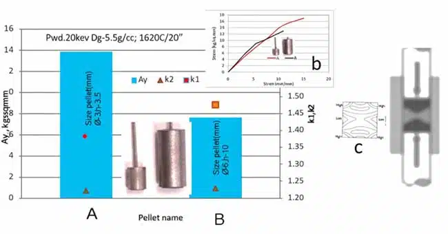
Pellet A demonstrated a yield strength approximately 40% higher than Pellet B, suggesting a larger cross-section of necks in its porous structure and superior heat dissipation. The variation in pellet size led to different stress distributions and density distributions, influencing neck size.

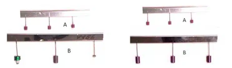
During the formation process, in the 0.01% H₃PO₄ electrolyte, Pellet A maintained its integrity, while Pellet B was destroyed. However, in the low-conductivity electrolyte consisting of 50% glycol and 0.05% H₃PO₄, both pellets underwent formation without destruction. The reduced conductivity in this electrolyte slowed down film growth and heat release, ensuring stability even for pellets with lower yield strength.

Behavior of pellets A and B during formation in 0.01% H₃PO₄ electrolyte (left) and  in low-conductivity electrolyte 50% glycol + 0.05% H₃PO₄

In summary – behavior during formation:

  • In 0.01% H₃PO₄ Electrolyte: 
    • Pellet A maintains integrity.
    • Pellet B is destroyed.
  • In Low-Conductivity Electrolyte (50% glycol + 0.05% H₃PO₄): 
    • Both pellets undergo formation without destruction.
    • Reduced conductivity slows film growth and heat release, ensuring stability even for pellets with lower yield strength.

Discussion

The discussion highlights several key points:

1. Heat Dissipation and Yield Strength Yield strength is correlated with the cross-sectional size of necks in the porous structure. Higher yield strength, at similar k₂ values, enhances heat dissipation.

2. Role of Pellet Size: Differences in pellet dimensions lead to varied stress distributions and heat dissipation capabilities.

3. Electrolyte and Film Growth Rate**: Lower electrolyte conductivity reduces oxide film growth rate, heat generation, and enhances pellet stability during formation.

4. Indirect Estimation of Stress Distribution: Stress distributions are not directly observable but can be inferred from stress-strain curves.

Conclusion

In conclusion, under identical technological parameters, the behavior of sintered tantalum pellets during formation is solely influenced by their size. Pressing and sintered density are not reliable indicators of the porous structure. Yield strength, correlating with neck size and heat dissipation, is the key factor in stability. For pellets with lower yield strength, reducing the oxide film growth rate using electrolytes of lower conductivity decreases heat generation and prevents destruction.

Appendix

Strain-Stress Curve Parameters for Porous Materials

Yield Stress (Ay): The yield stress of porous materials is related to the ratio of neck size (X) to primary powder particle size (D) by the equation:

Ay = b*A0*(X/D)², where b is an empirical constant, Ay is the yield point of the sintered porous material, and A0 is the yield point of the deformed material.

Young’s Modulus (k1 ~ E): Described by the equation: k1 ~ E = E0 (1-p/pc), where E is the elastic modulus of a porous material, E0 is the modulus of solid material at density pc ~ 1, and p is the porosity-related density.

Hardening Coefficient (k2 ~ P): An exponential coefficient correlating with material defectiveness.

Note: The size D determines BET.

References

Vladimir Azbel: Structural Interpretation of Reliability in Tantalum Capacitor Anodes

Related

Source: Azbel

Recent Posts

Nvidia Vera Rubin: Why One AI Rack Needs So Many More MLCC Capacitors

2.6.2026
12

Tecate Unveils High‑temp 105C Supercapacitors for Harsh‑Environment Designs

2.6.2026
6

Passive Components in 2026: From Invisible Commodity to Design Parameter

2.6.2026
15

May 2026 Interconnect, Passives and Electromechanical Components Market Insights

29.5.2026
87

Passive Components Enable Safe and Reliable ADAS Architectures

28.5.2026
64

YMIN Releases Square Supercapacitors for AI Server Power System

27.5.2026
51

Exxelia Extends Temperature Range of its PP Film Capacitors to 140C

1.6.2026
47

Nichicon Presents Self-Charging LTO Board for Maintenance-Free IoT Nodes

26.5.2026
28

Mechanical SSC Testing as a Structural Diagnostic Tool for Tantalum Capacitor Anodes

25.5.2026
50

Upcoming Events

Jun 16
16:00 - 17:00 CEST

EMC with EMC – EMC‑compliant design with electromechanical connectors

View Calendar

Popular Posts

  • Buck Converter Design and Calculation

    0 shares
    Share 0 Tweet 0
  • Boost Converter Design and Calculation

    0 shares
    Share 0 Tweet 0
  • Flyback Converter Design and Calculation

    0 shares
    Share 0 Tweet 0
  • MLCC and Ceramic Capacitors

    0 shares
    Share 0 Tweet 0
  • LLC Resonant Converter Design and Calculation

    0 shares
    Share 0 Tweet 0
  • Capacitor Charging and Discharging

    0 shares
    Share 0 Tweet 0
  • What Electronics Engineer Needs to Know About Passive Low Pass Filters

    0 shares
    Share 0 Tweet 0
  • Dual Active Bridge (DAB) Topology

    0 shares
    Share 0 Tweet 0
  • Ripple Current and its Effects on the Performance of Capacitors

    3 shares
    Share 3 Tweet 0
  • SEPIC Converter Design and Calculation

    0 shares
    Share 0 Tweet 0

Newsletter Subscription


Passive Components Blog

© EPCI - Leading Passive Components Educational and Information Site

  • Home
  • Privacy Policy
  • EPCI Membership & Advertisement
  • About

No Result
View All Result
  • Home
  • Knowledge Blog
  • Dossiers
  • PCNS

© EPCI - Leading Passive Components Educational and Information Site

This website uses cookies. By continuing to use this website you are giving consent to cookies being used. Visit our Privacy and Cookie Policy.
Go to mobile version