Passive Components Blog
No Result
View All Result
  • Home
  • NewsFilter
    • All
    • Aerospace & Defence
    • Antenna
    • Applications
    • Automotive
    • Capacitors
    • Circuit Protection Devices
    • electro-mechanical news
    • Filters
    • Fuses
    • Inductors
    • Industrial
    • Integrated Passives
    • inter-connect news
    • Market & Supply Chain
    • Market Insights
    • Medical
    • Modelling and Simulation
    • New Materials & Supply
    • New Technologies
    • Non-linear Passives
    • Oscillators
    • Passive Sensors News
    • Resistors
    • RF & Microwave
    • Telecommunication
    • Weekly Digest

    Researchers Presents High-Performance Carbon-Based Supercapacitors

    Hirose Launches World’s Lowest Profile and Narrowest Pitch FPC Connector

    Modelithics Announces v25.5 of the COMPLETE+3D Library for Ansys HFSS

    PCNS 2025 Final Program Announced!

    DigiKey Expands Inventory with Over 32,000 Stocking NPIs in Q2 2025

    YAGEO Offers High-Performance Diplexers for Dual-Band Wi-Fi 6E/7Integration

    European Components Distribution (DMASS) Faces Continued Decline in Q2 2025

    TDK Announced Wide Frequency Automotive Wirewound POC Inductors

    Bourns Released Rugged, High-Power TO-247 Thick Film Resistor

    Trending Tags

    • Ripple Current
    • RF
    • Leakage Current
    • Tantalum vs Ceramic
    • Snubber
    • Low ESR
    • Feedthrough
    • Derating
    • Dielectric Constant
    • New Products
    • Market Reports
  • VideoFilter
    • All
    • Antenna videos
    • Capacitor videos
    • Circuit Protection Video
    • Filter videos
    • Fuse videos
    • Inductor videos
    • Inter-Connect Video
    • Non-linear passives videos
    • Oscillator videos
    • Passive sensors videos
    • Resistor videos

    Switched Capacitor Converter Explained

    Understanding Inductor Dot Markings and Their Application in LTspice

    Accelerating Full Bridge LLC Resonant Converter Design with Frenetic AI

    Understanding Switched Capacitor Converters

    Coupled Inductors Circuit Model and Examples of its Applications

    Inductor Resonances and its Impact to EMI

    Highly Reliable Flex Rigid PCBs, Würth Elektronik Webinar

    Causes of Oscillations in Flyback Converters

    How to design a 60W Flyback Transformer

    Trending Tags

    • Capacitors explained
    • Inductors explained
    • Resistors explained
    • Filters explained
    • Application Video Guidelines
    • EMC
    • New Products
    • Ripple Current
    • Simulation
    • Tantalum vs Ceramic
  • Knowledge Blog
  • Suppliers
    • Who is Who
  • Events
No Result
View All Result
Passive Components Blog
No Result
View All Result

Thermocouple physics – How it works

4.10.2016
Reading Time: 3 mins read
A A

source: EDN article

Martin Rowe -October 02, 2016
Early in my editorial career, I wrote an article about thermocouples in Test & Measurement World where I incorrectly said that a voltage proportional to the junction temperature develops across the junction of two dissimilar metals. A reader wrote me a detailed letter (on paper, no e-mail then) explaining the Seebeck effect. Ever since, whenever I see anything about thermocouples using the incorrect description, I realize that yet another author is perpetuating the same old error.

RelatedPosts

Researchers Presents High-Performance Carbon-Based Supercapacitors

Hirose Launches World’s Lowest Profile and Narrowest Pitch FPC Connector

Modelithics Announces v25.5 of the COMPLETE+3D Library for Ansys HFSS

When Gordon Lee sent me his article Thermocouples: Basic principles and design essentials, I immediately looked for how he described thermocouple physics. He got it right. Jim Williams, however, made the same mistake I made.

While skimming through some EDN print issues, I ran across a letter to the editor written by Bill Dubé in the September 1, 1988 issue (Signals and noise, p.32). Dubé pointed out that Jim Williams made the same mistake in an article on thermocouple circuits from the May 26, 1988 issue, Clever techniques improve thermocouple measurements. EDN’s editors notified Williams of the letter. Jim did his homework and replied that he indeed got it wrong. See the text of the letter below, reprinted from the September 1 issue.

Some 20+ years after I made the same mistake, I feel exonerated, even though two wrongs don’t make a right (except in digital logic).

Thermocouple misconceptions are common

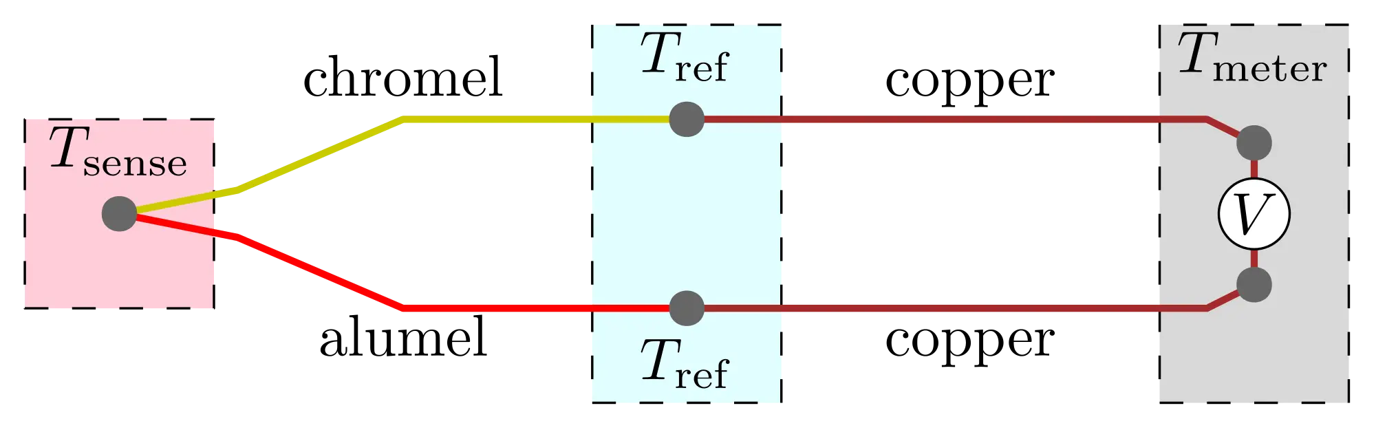
Jim Williams’s fine article “Clever techniques improve thermocouple measurements” (EDN, May 26, 1988, pg 145) is sadly flawed by a basic misunderstanding of the physics of thermocouples. It is a common misconception that the voltage of a thermocouple is generated across the junction. This is simply not true. The voltage is generated along the wires and is driven by the temperature difference between the sensing junction and the reference (“cold”) junction. For a given temperature difference, the two dissimilar wires generate unequal voltages. The voltage appearing across the thermocouple circuit at the reference junction is the difference between these unequal voltages.

The more technical explanation is that for a given temperature gradient dT/dx, an electric field dV/dx is generated. This electric field is a function of both dT/dx and absolute temperature. The local value of the difference dV/dT for a given alloy pair at a particular temperature is called the Seebeck coefficient. If the integral of the Seebeck coefficient is evaluated between-the sensing junction and the reference junction, the thermoelectric voltage results.

Thermal voltages in thermocouple circuits are always the result of thermal gradients. If a section of a thermocouple circuit has an unknown or undesirable Seebeck coefficient, then its influence can be diminished by suppressing thermal gradients in that section. For example, when you make a connection in a thermocouple circuit, it’s best to thermally anchor each of the wires to a common temperature before they reach the electrical connection point. The connection point should also be thermally anchored to this temperature. This procedure tends to suppress thermal gradients across the oxides, unknown alloys, etc, that make up the connection. If the thermal gradients are sup pressed, spurious thermal voltages will be reduced.

I hope this explanation will help clear up some of the misconceptions about the physics of thermocouples. Jim Williams is not alone in his misunderstanding—I have seen a remarkably similar treatment of thermocouples in a high-school physics text that is currently being used by the Denver School Dept.

Bill Dubé
Mechanical Engineer Denver, CO


Jim Williams responds:
Some friends and I have reviewed Bill Dubé’s comments and found them to be quite correct. As such, I find myself corrected, educated, and apologizing for any confusion I may have caused EDN’s readers. Although Bill’s distinctions are subtle, they are still the more correct interpretation, and I appreciate his remarks.

Related

Recent Posts

Researchers Presents High-Performance Carbon-Based Supercapacitors

1.8.2025
8

Würth Elektronik Expands MagI³C with Variable Step-Down Modules

30.7.2025
18

Switched Capacitor Converter Explained

28.7.2025
25

Researchers Demonstrated 200C Polymer Film Dielectric

28.7.2025
14

Researchers Demonstrated Zinc-Ion Based Photo-Supercapacitor

28.7.2025
12
Comparative display of a grain size and domain structure; b free energy; c P-E loops after high-entropy ceramics (HECs) and PGS design. source: Nature Communications  ISSN 2041-1723

Researchers Propose Novel MLCC Dielectric Design to Increase Energy Storage Capacity

24.7.2025
45

DigiKey Offers Zephyr Operating System Workshop and Training Videos

6.6.2025
21

H2-Assisted Thermal Treatment of Electrode Materials Increases Supercapacitors Energy Density

13.5.2025
14

How to design a 60W Flyback Transformer

12.5.2025
124

Researchers Present Hybrid Supercapacitor Zn-Ion Microcapacitors

12.5.2025
59

Upcoming Events

Sep 22
September 22 @ 13:00 - September 25 @ 15:15 EDT

Pre Cap Visual Inspection per Mil-Std-883 (TM 2017)

Sep 30
September 30 @ 12:00 - October 2 @ 14:00 EDT

MIL-Std-883 TM 2010

Oct 17
12:00 - 14:00 EDT

External Visual Inspection per MIL-STD-883 TM 2009

Oct 21
October 21 @ 12:00 - October 23 @ 14:15 EDT

Space and Military Standards for Hybrids and RF Microwave Modules

Nov 4
November 4 @ 12:00 - November 6 @ 14:15 EST

Wirebond Materials, Processes, Reliability and Testing

View Calendar

Popular Posts

  • Buck Converter Design and Calculation

    0 shares
    Share 0 Tweet 0
  • Boost Converter Design and Calculation

    0 shares
    Share 0 Tweet 0
  • Flyback Converter Design and Calculation

    0 shares
    Share 0 Tweet 0
  • LLC Resonant Converter Design and Calculation

    0 shares
    Share 0 Tweet 0
  • What is a Dielectric Constant and DF of Plastic Materials?

    4 shares
    Share 4 Tweet 0
  • Ripple Current and its Effects on the Performance of Capacitors

    3 shares
    Share 3 Tweet 0
  • How to Design an Inductor

    0 shares
    Share 0 Tweet 0
  • Dual Active Bridge (DAB) Topology Explained

    0 shares
    Share 0 Tweet 0
  • MLCC Case Sizes Standards Explained

    0 shares
    Share 0 Tweet 0
  • MLCC and Ceramic Capacitors

    0 shares
    Share 0 Tweet 0

Newsletter Subscription


Passive Components Blog

© EPCI - Leading Passive Components Educational and Information Site

  • Home
  • Privacy Policy
  • EPCI Membership & Advertisement
  • About

No Result
View All Result
  • Home
  • Knowledge Blog
  • Premium Suppliers

© EPCI - Leading Passive Components Educational and Information Site

This website uses cookies. By continuing to use this website you are giving consent to cookies being used. Visit our Privacy and Cookie Policy.
Go to mobile version