


Power-line energy harvesting using current transformers offers an elegant way to power distributed electronics directly from existing AC conductors. This tutorial by Sam Ben‑Yaakov focuses on the magnetic design aspects of such harvesters, showing how core material, geometry, turns ratio and loading determine the maximum usable power and how designers can use simulation to optimize their design.
Key features and benefits
- Use of a current transformer architecture (single‑turn primary, multi‑turn secondary) for both current sensing and power harvesting from AC lines.
- Clear separation between the measurement function (current transformer as sensor) and harvesting function (rectified and conditioned output to a load).
- Emphasis on core saturation as the dominant limiting factor for harvested power in transformer‑based systems.
- Use of nonlinear inductor modeling in LTspice to represent real B–H behavior and saturation of ferromagnetic cores.
- Demonstration of how core cross‑section, path length and relative permeability influence magnetizing inductance and maximum voltage.
- Identification of an optimal reflected load resistance RP that maximizes harvested power for given line current and core.
- Illustration of operation in linear, near‑saturation and deep saturation regimes, including typical power levels in each case.
- Discussion of rectification options (diode bridge vs active rectifier) and their impact on flux waveforms and saturation.
- Practical guidance on using power‑factor‑correction or DC‑DC stages to emulate an adjustable input resistance and implement maximum power point tracking (MPPT).
- Design‑level guidance suitable for engineers specifying cores, turns ratios and loads in energy‑harvesting current transformers.
| Aspect | Benefit for designers |
|---|---|
| Current transformer usage | Non-intrusive harvesting from existing AC lines via clamp-on cores |
| Focus on magnetic design | Clear understanding of saturation limits and power capability |
| Nonlinear LTspice modeling | Realistic prediction of core behavior and flux waveforms |
| Core parameter tuning | Ability to trade off size, material and power level |
| Load optimization | Identification of an optimal reflected resistance for max power |
| Rectifier topology choice | Control over efficiency and saturation behavior |
| MPPT/control integration | Stable operation over varying line currents and loads |
Typical applications
Although the video does not enumerate application markets, the presented approach is directly relevant to:
- Clamp‑on sensor nodes on LV or MV AC distribution lines.
- Powering condition‑monitoring or metering electronics from the current in busbars, feeders or industrial mains.
- Retrofitted sensing on existing wiring where adding a dedicated low‑voltage supply is impractical.
- Non‑intrusive power for data loggers or communication modules mounted along overhead or buried cables.
- Long‑term autonomous sensor operation where battery replacement is costly and grid access is nearby.
In all of these use cases, the magnetic element is a key passive component, and its proper selection and modeling are crucial for reliable long‑term operation.
Technical highlights
From current transformer to harvester
The starting point is the well‑known current transformer. A single‑turn primary is formed by the AC line passing through a toroidal or split core, and the secondary has turns feeding a burden resistor . The secondary current is approximately , with the primary (line) current, and the voltage across is . This configuration is used to measure AC currents, with appropriate selection of core, turns and burden for the frequency range of interest.
To turn this into a harvester, the burden resistor is replaced by a rectifier and typically a DC‑DC converter that stabilizes the DC voltage and optimizes power extraction. The secondary then feeds a real load, such as a sensor system or battery charger. The tutorial explicitly focuses on the magnetic part of this structure, not on detailed converter electronics.
Core saturation and voltage as the limiting factor
The core material has a B–H characteristic with saturation: as the magnetic field increases, the magnetic flux density eventually reaches a maximum beyond which further increases in produce little change in . This is true for all practical ferromagnetic cores; only air cores are exempt, but their coupling is too weak for this application.
A central point of the tutorial is that it is the applied voltage, not directly the current, that drives the core into saturation. Under normal transformer operation, the primary and secondary currents are arranged so that their magnetizing effects largely cancel, according to Lenz’s law. Even with high load current, the net magnetizing current can remain small. The flux in the core is related to the applied voltage and frequency via Faraday’s law:where n is the number of turns, the core cross‑section and the flux density. Integrating over time shows that for a given , there is an upper limit to the volt‑seconds that may be applied each half‑cycle. Once this limit is exceeded, the core saturates; at that point the voltage collapses and current maintains the saturated state.
For harvesting, this means that the maximum available power is fundamentally limited by the maximum allowable voltage at a given frequency and core geometry.
| Core/design parameter | Change direction | Typical effect on magnetizing inductance and power capability |
|---|---|---|
| Relative permeability | Ferrite → nanocrystalline | Higher : higher inductance, higher possible harvesting voltage |
| Saturation flux | 0.3 T → 1 T | Higher more volt‑seconds before saturation |
| Cross‑section area | Small → large | Larger : lower flux density for same voltage, higher power headroom |
| Magnetic path length | Long → short | Shorter : higher inductance for same material and cross‑section |
| Turns ratio | 1:100 → 1:200 | Higher : higher secondary voltage, lower current |
| Line frequency | 50 Hz → 60 Hz | Higher f higher reactance, more voltage for same current |
Magnetizing inductance and core parameters
The transformer is modeled as an ideal transformer with a magnetizing inductance in parallel on the primary side. The magnetizing inductance is determined by:
- Core cross‑section area: larger yields higher .
- Magnetic path length: shorter path yields higher L
- Relative permeability: higher yields higher .
A higher inductance increases the reactance at the line frequency, which in turn allows higher voltage for a given current. The power delivered to the load (reflected to the primary as ) is:so higher voltage directly increases power for a given .
The tutorial highlights that for high‑power harvesting, materials with high relative permeability and high , such as suitable nanocrystalline alloys, are beneficial. For lower power levels, standard ferrite cores can be sufficient.
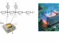
Equivalent circuit for harvesting
On the primary side, the line current is treated as a current source, since the harvester extracts only a small portion of the energy and the additional voltage drop is small. The equivalent circuit comprises:
- An AC current source representing the line current.
- A magnetizing inductance representing the core.
- A reflected load resistance in parallel with the magnetizing inductance.
The primary voltage is then:where is the parallel combination of the magnetizing reactance and . This voltage produces flux in the core according to Faraday’s law. The power delivered to the load depends on how the current source splits between the magnetizing branch and the reflected load branch.
The tutorial points out the “play” between and the magnetizing impedance:
- If is very small, most current flows through RP but the voltage is low, so the power is low.
- If is very large (ignoring saturation for the moment), most current flows through the inductance; the voltage can be high but the current through is small, so again power is low.
Therefore, an optimum exists where the product is maximized without driving excessive saturation.
Nonlinear inductor modeling in LTspice
To analyze this behavior in detail, the tutorial uses a nonlinear inductor model in LTspice. The flux is defined as a function of current using a hyperbolic tangent, which mimics the saturating behavior of ferromagnetic cores:
- The tanh function is symmetric and has a linear region around zero, followed by a gradual saturation.
- Two constants and are used such that their ratio equals the inductance in the linear region.
- In the example, the resulting inductance is for the single‑turn primary.
The flux density is then obtained by integrating the voltage across the inductor and scaling by turn count and core area:Assuming a cross‑section of (i.e. ) gives in Tesla. This integration is implemented as a behavioral voltage source using LTspice’s integration operator, allowing to be plotted during simulation.
A current source of 100 A at 50 Hz is used to drive the inductor as a stand‑alone element. Simulation shows that at 100 A peak, the core saturates, producing a distorted voltage waveform and a flux density waveform limited to about 1 T. Plotting versus current yields the B–I curve, showing saturation at around 50–60 A for this particular model.
Transformer model and resistive load
Building on the nonlinear inductor, the tutorial constructs a full transformer harvester model:
- The magnetizing inductance is the nonlinear inductor.
- An ideal transformer is implemented with two large inductances, 1 H for the primary and 40 kH for the secondary, giving an effective turns ratio of 1:200 since inductance scales as ().
- A resistive load is connected across the secondary; its value is parameterized (e.g. 30 Ω, 10 Ω, higher values).
- A behavioral expression multiplies load current and voltage to obtain instantaneous power, whose average is the harvested power.
The line current is modeled as a 10 A or 50 A AC source.
Operating points and power levels
Several operating points are demonstrated:
- 10 A line current, 30 Ω secondary load
The core operates in the linear region, with flux density around 200 mT. Waveforms are sinusoidal. The primary current is slightly higher than the magnetizing current; the 90° phase shift between them means the vector sum equals the 10 A line current. The instantaneous power peaks around 50 mW, with an average of about 25 mW. - 50 A line current, 30 Ω secondary load
The core operates close to saturation, with flux density reaching about 1 T. Some waveform distortion appears. The peak instantaneous power is about 1 W, and the average harvested power is about 0.5 W. This is a useful power level for many sensor applications where a few hundred milliwatts suffice. - 50 A line current, 10 Ω secondary load
The core returns to deep linear operation, with flux density around 40 mT. The voltage across the load is lower, and the average power is about 300 mW, less than at the 30 Ω load, despite remaining comfortably away from saturation. - 50 A line current, high secondary resistance
With much higher load resistance, the system becomes highly saturated. The voltage attempts to rise but is limited by Bmax. Most current flows through the nonlinear magnetizing branch; current through the high resistance is small. The power is again low, on the order of a few hundred milliwatts or less, and the conduction interval is narrow.
These examples illustrate that:
- There is an optimal load resistance for maximum harvested power.
- Operating near, but not deeply into, saturation can be beneficial for maximizing power.
- Both too low and too high load resistances reduce power, by different mechanisms.
Rectifier‑based harvester and flux waveforms
The tutorial then moves from pure AC resistive loading to a more realistic rectified harvester:
- The secondary is connected to a diode bridge feeding a DC load modeled as a constant voltage source (e.g. 2 V load plus diode drops for about 3 V total).
- The voltage at the secondary becomes a square wave corresponding to the rectifier conduction, and so does the primary voltage.
- With a square‑wave voltage, flux density becomes a triangular waveform: it ramps linearly up and down between minimum and maximum values each half‑cycle.
In the case of a 3 V total DC load, the flux density remains around 300 mT, indicating safe operation within the linear region. The current splits between the nonlinear magnetizing branch and the ideal transformer branch, and useful power is delivered to the DC load.
Raising the DC load voltage (for example, to 4 V at the load, about 5 V at the bridge output) increases the square‑wave amplitude and pushes the core into saturation. The flux density reaches 1 T and holds there for intervals of the cycle, with additional oscillations attributed to numerical artifacts. Physically, this represents the transformer entering a regime where the secondary effectively opens when the voltage collapses, so the secondary cannot conduct, and the magnetizing current dominates.
This is a problematic state for hardware: it can cause noise, long‑term core magnetization and uncontrolled behavior.
Protection by shorting the secondary
To mitigate saturation problems in practical designs, the tutorial suggests shorting the secondary during saturation intervals. If an active rectifier is used (e.g. a MOSFET bridge), the control circuitry can:
- Detect the onset of saturation (via flux‑related signals or other indicators).
- Turn on a pair of MOSFETs (either both low‑side or both high‑side devices) to short the secondary.
- Release the short once the core has returned to a safe operating region.
Shorting the secondary during saturation prevents the core from remaining magnetized, reduces noise and protects the magnetic element without harming the transformer. It is presented as an important system‑level design measure for high‑power harvesters.
Maximum power point and emulated load resistance
Because harvested power is highly sensitive to the effective load resistance, the tutorial notes that maximum power point tracking is desirable in real applications. An active power factor correction front end or a DC‑DC converter can emulate a tunable input resistance:
- By adjusting duty cycle or control setpoints, the converter changes the effective input resistance seen by the transformer secondary.
- A control algorithm can scan or track the load resistance that maximizes measured output power.
- Once the optimal reflected RP is found, the system can maintain operation at this point as line conditions vary.
The stored energy typically feeds a charging circuit for a battery or supercapacitor that powers the actual load (sensor, radio, etc.). In simpler applications, designers may omit the intermediate converter and connect a rectifier directly to the line, but the video stresses that in such cases the operating point is fixed and must be carefully chosen with respect to saturation and power needs.
Design‑in notes for engineers
For passive component and magnetics engineers specifying cores and windings for transformer‑based line harvesters, the tutorial suggests several practical guidelines:
- Core material selection
- Prefer high‑permeability materials with high when higher harvested power is required. Nanocrystalline cores are highlighted as suitable candidates for such applications, combining high relative permeability with high saturation flux density.
- For lower power requirements, ferrite cores remain viable, provided designers respect the lower and frequency constraints.
- Core geometry
- Increase cross‑section area to raise magnetizing inductance and reduce flux density for a given voltage.
- Minimize magnetic path length l within mechanical and insulation constraints to further increase inductance.
- Turns ratio
- Use the relationship to relate inductance to turns.
- For current transformer‑like harvesters, a single‑turn primary (the conductor) and large‑turn secondary (e.g. 200 turns) is typical; in the example, a 1:200 ratio is realized by a 1 H primary and 40 kH secondary in the ideal transformer model.
- Saturation margin
- Derive a target from the material’s datasheet.
- Use simulation (with nonlinear inductance) to ensure that, at the highest anticipated line current and operating load, the flux density waveform remains within acceptable limits most of the time. Near‑saturation operation can be acceptable for maximizing power, but prolonged deep saturation should be avoided.
- Load resistance selection
- Recognize that the effective seen by the primary critically affects harvested power.
- For fixed‑resistor designs, choose (and thus ) based on simulation or calculation to approximate the maximum‑power operating point for the expected line current range.
- For converter‑based designs, incorporate a control function that can adjust the effective input resistance dynamically.
- Rectifier and control topology
- Use diode bridges for simplicity at the cost of conduction losses and potential exacerbation of saturation.
- For higher power and better control, employ MOSFET‑based active rectifiers, which reduce losses and offer the ability to short the secondary during saturation.
- Consider integrating MPPT logic into the DC‑DC stage or PFC front end to maintain optimum power extraction over varying conditions.
- Simulation methodology
- Start with a nonlinear inductor model calibrated to the intended core and winding (using material data and desired inductance).
- Implement an ideal transformer with realistic turns ratio and large inductances to focus on magnetizing behavior.
- Include realistic line current levels and sweep both current and load resistance.
- Plot not only voltages and currents but also flux density and instantaneous power to visualize saturation and harvested power.
These design‑in considerations connect directly to the passive components that readers of a passive‑components‑focused portal select and specify: core material, core shape, winding strategy and burden / load components.
| Line current (A) | Secondary load (Ω) | Flux region (qualitative) | Approx. average harvested power | Notes |
|---|---|---|---|---|
| 10 | 30 | Linear (~200 mT) | Tens of milliwatts | Clean sinusoidal waveforms, ample saturation margin |
| 50 | 30 | Near saturation (~1 T) | Roughly half a watt | High power, moderate distortion, practical target |
| 50 | 10 | Deep linear (~40 mT) | Few hundred milliwatts | Lower voltage, reduced power compared to optimum |
| 50 | High (>>30 Ω) | Deep saturation (~1 T) | Reduced, few hundred milliwatts | Narrow conduction, noisy behavior, not recommended |
Source
The information in this article is based on a technical tutorial video by Sam Ben‑Yaakov, focusing on the fundamentals of transformer‑based power‑line harvesting and the magnetic design considerations behind it. Exact numeric limits and material properties should be verified against the manufacturer datasheet of the specific core and components selected in a design.
Frequently Asked Questions: Transformer-Based Power-Line Harvesting
Transformer-based power-line harvesting uses a current transformer clamped around an AC conductor to extract a small amount of power from the line current. The primary is the existing power line (one turn), and the secondary is a multi-turn winding feeding a rectifier and often a DC-DC converter that powers sensors or monitoring electronics.
A standard current transformer is designed for measurement and feeds a burden resistor to generate a proportional voltage signal. In a harvester, the secondary output is rectified and used to deliver real power to a load, so core selection, saturation limits and load resistance become critical design parameters rather than just accuracy and bandwidth.
The dominant limit is core saturation, which is driven by the applied voltage, frequency, number of turns and core cross-section. Once the flux density approaches the material’s maximum Bmax, the core saturates, waveforms distort and the effective power transfer drops, so the design must keep volt-seconds within the material’s limits.
Under normal transformer operation, primary and secondary currents largely cancel magnetically due to Lenz’s law, so high load current alone does not necessarily cause saturation. It is the voltage across the winding, together with frequency and turns, that primarily determines flux build-up and saturation, while current maintains saturation once the voltage collapses.
Magnetizing inductance sets the impedance of the core at line frequency and thus how much voltage can develop for a given line current. Higher inductance, achieved by using a larger cross-section, shorter path length and higher relative permeability, allows a higher voltage before saturation and therefore higher potential harvested power for a given reflected load.
The core is modeled as a nonlinear inductor whose flux is a function of current using a hyperbolic tangent relationship. Two constants define the shape so that their ratio gives the inductance in the linear region, and a behavioral source integrates the inductor voltage over time and scales it by turns and core area to obtain flux density B(t) during simulation.
Yes. If the reflected load resistance is too low, voltage stays small and power remains limited; if it is too high, the core saturates and current through the load drops. Simulations show that for each combination of line current and core, there is an intermediate reflected resistance that maximizes average harvested power while keeping saturation under control.
A diode bridge or active rectifier produces a square-wave voltage at the transformer secondary, which results in a square-wave primary voltage and a triangular flux waveform. At moderate DC output voltages, the flux stays within a safe range; as the DC output voltage increases, the flux ramps to Bmax, causing saturation, waveform clipping and reduced effective power transfer.
When the transformer saturates and the secondary voltage collapses, the secondary effectively behaves like an open circuit, leading to noise and undesirable core magnetization. Shorting the secondary during these intervals, for example with controlled MOSFETs in an active bridge, protects the core, reduces acoustic and electrical noise and avoids long-term magnetization problems.
A DC-DC converter or active power factor correction stage can emulate an adjustable input resistance at the transformer secondary. By monitoring voltage and current and adjusting control parameters, the converter can seek and hold the operating point that yields maximum harvested power under varying line currents and load conditions, similar to MPPT in photovoltaic systems.
How to Design a Transformer-Based Power-Line Harvester
- Step 1: Define power and line-current requirements
Start by specifying the approximate power level you need to harvest and the range of line currents available on the target conductor. Use realistic worst-case and nominal current values, as the available power scales with line current and will influence core choice, turns ratio and load resistance.
- Step 2: Select core material and geometry
Choose a magnetic core material with suitable relative permeability and saturation flux density Bmax. For higher harvested power, consider nanocrystalline materials with high permeability and high Bmax; for lower power, ferrite may suffice. Select a geometry with sufficient cross-section area and a reasonably short magnetic path to achieve a high magnetizing inductance.
- Step 3: Choose turns ratio and winding arrangement
Use the power line as a single-turn primary and design the secondary with enough turns to achieve the desired voltage level after rectification. Remember that inductance scales with n2, so a higher turns ratio increases both secondary voltage and effective magnetizing inductance. Ensure the winding layout respects insulation, creepage and clearance requirements for the line voltage.
- Step 4: Build a nonlinear inductor model in LTspice
Create a nonlinear inductor whose flux depends on current using a hyperbolic tangent expression calibrated so that the linear-region inductance matches your target magnetizing inductance. Add a behavioral integration block that computes flux density B(t) from the inductor voltage using , with the intended core cross-section area.
- Step 5: Assemble the transformer and load equivalent circuit
Model the line current as an AC current source feeding the primary. Connect the nonlinear magnetizing inductance in parallel with an ideal transformer whose inductances follow the chosen turns ratio. On the secondary, attach a parameterized resistive load and include a behavioral block that multiplies voltage and current to compute instantaneous and average harvested power.
- Step 6: Simulate linear and near-saturation operating points
Run simulations for different line currents and load resistances, starting with modest currents and mid-range loads. Observe primary and secondary voltages, currents, flux density waveforms and average harvested power. Identify the current levels where flux density approaches \( B_{\text{max}} \) and note the corresponding power output to understand your practical operating envelope.
- Step 7: Sweep load resistance to find maximum power
For one or more line-current levels, sweep the secondary load resistance to see how average harvested power changes. Look for the reflected load resistance that maximizes power without driving the core into deep saturation. Use these results to define an optimal load range for your hardware or an initial target for any future maximum power point tracking algorithm.
- Step 8: Add rectification and DC load modeling
Replace the resistive AC load with a rectifier, such as a diode bridge, feeding a DC load represented by a constant voltage source. Simulate the system again to examine how square-wave secondary voltage and triangular flux change saturation behavior. Evaluate flux density and power for different DC load voltages to ensure the design remains within safe magnetic limits at the required DC output.
- Step 9: Plan protection and control measures
If simulations show extended saturation intervals at certain operating points, incorporate protection mechanisms such as actively shorting the secondary during saturation when using a MOSFET bridge. For designs targeting higher power or wide line-current ranges, consider adding a DC-DC stage with control logic to emulate a tunable input resistance and perform maximum power point tracking based on measured power.
- Step 10: Translate simulation results into hardware design
Use the validated simulation parameters to finalize core material, dimensions, turns count, wire gauge and insulation strategy. Select rectifier and converter components rated for the expected voltages and currents. Build a prototype and compare measured flux, voltage and harvested power against the simulated results, then refine the design to meet your application’s performance and reliability targets.
References
- The fundamentals of transformer-based power-line harvesting: A tutorial, Sam Ben-Yaakov, YouTube. https://www.youtube.com/watch?v=PjWEvqRt4sg
- Simulating a physical inductor using LTspice, Sam Ben-Yaakov, YouTube. https://www.youtube.com/watch?v=rWPFbiu5o2s