


This presentation from Würth Elektronik Midcom by Aldo de Michiel provides a structured exploration of transformer design optimization, with detailed insights into each stage of the design process.
Transformer design is a cornerstone of modern power electronics. The choice of package, core, insulation, and winding strategy determines not only efficiency but also compliance with safety standards and electromagnetic compatibility.
By expanding on package selection, core material choice, safety compliance, EMI mitigation, and custom design workflows, we aim to provide engineers with a comprehensive reference for decision-making.
Key Takeaways
- Transformer design optimization is crucial for efficiency, safety compliance, and electromagnetic compatibility.
- Key factors include package selection, core geometry, insulation systems, and EMI mitigation.
- A systematic approach helps in selecting components that balance performance, cost, and manufacturability.
- Regulatory compliance requires careful design considerations to ensure safety and reliability throughout product life.
- A thorough custom design workflow ensures robust manufacturing and quality control, leading to efficient transformer solutions.
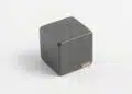
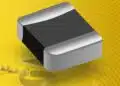
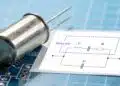
Chapter 1: Transformer Package Selection
1.1 Electrical Performance Considerations
The package defines winding window area, leakage inductance, and thermal dissipation. For example, toroidal packages minimize leakage inductance but complicate automated assembly. EE and ETD cores provide flexibility in winding arrangements, while EFD cores are optimized for low-profile applications.
1.2 Mechanical Integration
Height restrictions in low-profile designs (e.g., laptops, LED drivers) favor EFD cores, while industrial systems tolerate taller ETD cores. Pin orientation (horizontal vs. vertical) impacts PCB routing and assembly density. Designers must also consider mechanical robustness under vibration and shock.
1.3 Manufacturability and Automation
SMD-compatible packages like EFD and EP cores are optimized for pick-and-place automation. Through-hole packages remain common in high-power designs due to mechanical robustness and higher creepage distances. Automated winding machines also favor certain bobbin geometries.
1.4 Cost vs. Performance Trade-offs
Compact packages reduce material costs but may increase copper losses due to limited winding area. Larger packages improve efficiency but raise BOM cost and footprint. The optimal choice balances efficiency, cost, and manufacturability.
| Package Type | Power Range | Profile | Automation Suitability | Typical Applications |
|---|---|---|---|---|
| EP7 | Up to 3W | Low | High | Signal isolation, small DC/DC converters |
| ETD39 | Up to 400W | High | Medium | Industrial power supplies, chargers |
| EFD10 | Up to 10W | Ultra-low | High | Consumer electronics, LED drivers |
| PQ35 | Up to 250W | Medium | Medium | Telecom, automotive DC/DC |
Chapter 2: Core Selection and Magnetic Design
2.1 Core Geometry
Core geometry determines flux path length and winding utilization. RM cores provide excellent shielding, while PQ cores maximize winding area for high-current applications. EE cores are versatile and widely available, while toroidal cores minimize leakage but are harder to wind.
2.2 Core Material Properties
Ferrites dominate high-frequency applications due to low eddy current losses. Powdered iron cores tolerate higher DC bias but suffer higher losses at switching frequencies above 200 kHz. Nanocrystalline materials offer high permeability and low losses but at higher cost.
2.3 Power Handling and Frequency Scaling
The maximum transferable power is proportional to effective cross-sectional area and switching frequency: P∝Ae×f
Higher frequencies allow smaller cores but increase switching losses. Designers must balance core size, frequency, and efficiency.
2.4 Thermal Considerations
Core losses generate heat that must be dissipated. Designers must evaluate thermal resistance from core to ambient and consider forced-air cooling in high-power designs. Thermal runaway can occur if losses exceed dissipation capacity.
| Core Material | Frequency Range | Loss Characteristics | Cost | Applications |
|---|---|---|---|---|
| Manganese-Zinc Ferrite | 20 kHz – 500 kHz | Low loss, moderate saturation | Low | General SMPS, chargers |
| Nickel-Zinc Ferrite | 500 kHz – 5 MHz | Higher resistivity, lower permeability | Medium | High-frequency DC/DC |
| Powdered Iron | Up to 200 kHz | High DC bias tolerance, higher losses | Low | Inductors, PFC chokes |
| Nanocrystalline | 20 kHz – 200 kHz | Very low loss, high permeability | High | High-end inverters, EV chargers |
Chapter 3: Safety Compliance and Standards
3.1 Insulation Systems
Insulation is classified as functional, basic, supplementary, or reinforced. Reinforced insulation often requires triple-insulated wire or physical barriers. The choice depends on application safety requirements (e.g., medical vs. consumer).
3.2 Clearance and Creepage Distances
Standards such as IEC 61558-1 and IEC 60601-1 define minimum distances between conductive parts. These depend on pollution degree, overvoltage category, and altitude. For example, reinforced insulation in medical devices requires larger creepage distances than in consumer electronics.
3.3 Thermal Class and Lifetime
Insulation materials are rated by thermal class (e.g., Class B: 130°C, Class F: 155°C). Exceeding these limits reduces transformer lifetime exponentially. Designers must ensure that winding and core temperatures remain within limits under worst-case conditions.
3.4 Regulatory Testing
Dielectric withstand tests (HiPot), partial discharge tests, and surge tests validate compliance. Early design alignment with standards reduces redesign cycles and certification delays.
| Insulation Grade | Layers Required | Typical Voltage Withstand | Application Examples |
|---|---|---|---|
| Functional | 0 | Up to 250 V | Non-critical circuits, extra-low voltage |
| Basic | 1 | 250–1,500 V | General electronics, appliances |
| Supplementary | 2 | 1,500–3,000 V | Enhanced consumer/industrial safety |
| Reinforced | 3+ or barriers | 3,000–5,000 V | Medical, high-isolation industrial |
Chapter 4: EMI Considerations
4.1 Core Shape and Magnetic Shielding
Closed magnetic path cores (e.g., RM, PQ) reduce stray fields and radiated EMI. Open cores (e.g., EE, ETD) can be more susceptible to leakage flux and may require shielding in sensitive systems. Selecting core geometry early helps meet radiated emissions targets without excessive filtering.
4.2 Winding Layout Strategies
Interleaving primary and secondary reduces leakage inductance but increases interwinding capacitance, which can raise common-mode noise. Layered winding with margin tape maintains creepage and clearance, while foil windings can lower AC resistance in high-current designs. Each layout must be matched to the converter topology and EMI limits.
4.3 Parasitic Capacitance Control
Electrostatic shields between windings reduce common-mode noise into secondary circuits, at the cost of added capacitance to ground and manufacturing complexity. Split bobbins inherently reduce coupling (and capacitance) but increase leakage inductance. Balancing parasitics is essential to avoid both excessive ringing and poor efficiency.
4.4 Compliance with EMI Standards
Power electronic equipment must comply with standards such as CISPR 22/32 and FCC Part 15 for conducted and radiated emissions. Early pre-compliance testing with representative loads, realistic cabling, and worst-case ambient conditions prevents late-stage surprises. Component selection (e.g., core material, wire type) directly impacts emissions performance.
| EMI Technique | Primary Benefit | Trade-off | Typical Use Case |
|---|---|---|---|
| Interleaved windings | Low leakage inductance | Higher capacitance | Forward/bridge converters |
| Electrostatic shield | Lower common-mode noise | Complexity, added capacitance to ground | Precision analog, medical |
| Split bobbin | Low interwinding capacitance | High leakage inductance | Isolation-heavy, low-frequency |
| Margin tape | Improved creepage | Reduced window area | Reinforced insulation builds |
Chapter 5: Custom Design Workflow
5.1 Specification Gathering
A comprehensive specification should capture electrical parameters (input range, output(s), power, ripple), isolation requirements (working voltage, surge, insulation class), environment (ambient range, altitude, pollution degree), and mechanical constraints (height, footprint, pin style). Clear upfront data minimizes iterations and risks during certification.
5.2 Simulation and Prototyping
Magnetic design tools estimate core losses and flux density versus frequency, while circuit simulation validates dynamic response and stress across windings. Thermal simulations guide material choices and cooling strategies. Rapid prototypes confirm manufacturability and reveal real-world parasitics not captured in models.
5.3 Design Trade-offs
Transformer optimization involves balancing efficiency, EMI, size, and cost. For instance, increasing turns lowers flux density but raises copper loss; interleaving improves coupling but can worsen common-mode emissions. Documenting trade-offs ensures stakeholders understand performance boundaries and certification implications.
5.4 Manufacturing and Quality Control
Process controls—winding tension, layer order, insulation integrity, and solder quality—drive reliability. Electrical tests (turns ratio, inductance, leakage, HiPot), thermal burn-in, and AOI catch defects early. PPAP/FAI documentation and SPC on critical dimensions (e.g., creepage features) stabilize volume production.
| Workflow Stage | Key Activities | Primary Outputs | Risk Mitigation |
|---|---|---|---|
| Requirements | Collect specs, constraints, standards | Design brief, compliance matrix | Gap analysis, stakeholder alignment |
| Preliminary design | Core/package selection, draft winding | BoM, drawings, simulations | DFMEA, early EMI review |
| Prototyping | Sample builds, test plans | Test reports, refinements | Pre-compliance measurements |
| Validation | Reliability, environmental, safety tests | Certification readiness | Design freeze criteria |
| Production | Process control, QC, traceability | Stable yield, lot records | SPC, audit, corrective actions |
Conclusion
Optimizing transformer design for power electronics requires a disciplined approach: select the right package for mechanical and thermal realities, choose core geometry and materials that align with frequency and power goals, engineer insulation to meet safety standards without sacrificing window utilization, and tame EMI through deliberate winding layouts and parasitic control.
A robust custom workflow—grounded in complete specifications, validated by simulation and prototypes, and sustained by manufacturing quality—turns these choices into reliable products. When trade-offs are explicitly managed and tested early, teams achieve efficient, compliant, and scalable transformer solutions.
Further Read:
Transformer Topologies in Power Converters
Frequently Asked Questions (FAQ)
Transformer package selection is influenced by electrical performance, mechanical integration, manufacturability, and cost-performance trade-offs. The choice impacts winding area, thermal dissipation, EMI behavior, and compliance with PCB constraints.
Ferrite cores, particularly manganese-zinc and nickel-zinc types, are preferred for high-frequency applications due to their low eddy current losses. Nanocrystalline cores are also used in advanced designs where efficiency and low loss are critical.
Safety standards such as IEC 61558-1 and IEC 60601-1 define insulation requirements, creepage and clearance distances, and testing protocols. Compliance ensures transformers meet isolation, thermal, and dielectric withstand requirements for safe operation.
Techniques include interleaved windings, electrostatic shields, split bobbins, and careful core geometry selection. Each method balances leakage inductance, capacitance, and manufacturability to meet EMI compliance standards.
The workflow includes specification gathering, simulation and prototyping, design trade-off analysis, and manufacturing with quality control. Each stage ensures the final transformer meets performance, safety, and cost requirements.
How to Optimize Transformer Design
- Define Requirements
Collect input/output voltages, power levels, isolation requirements, safety standards, and mechanical constraints. This forms the foundation of the design brief.
- Select Package and Core
Choose a transformer package that fits mechanical and thermal needs, and select a core geometry and material that align with switching frequency and power density goals.
- Design Windings and Insulation
Develop winding layouts that balance leakage inductance and capacitance. Apply insulation systems that meet regulatory requirements for creepage, clearance, and dielectric strength.
- Simulate and Prototype
Use magnetic and thermal simulations to predict performance. Build prototypes to validate assumptions, measure parasitics, and refine the design.
- Validate Safety and EMI Compliance
Perform HiPot, partial discharge, and EMI pre-compliance testing. Adjust shielding, winding, or materials as needed to meet standards.
- Transition to Manufacturing
Implement process controls, quality checks, and documentation. Ensure consistency through AOI, electrical testing, and statistical process control.