


This Frenetic blog article from Pablo Blázques provides introduction to the basic transformer topologies in power converters and its key features.
Usually, in all the transformer topologies, we have an input filter (inductance before the primary side of our transformer), the transformer itself and the output filter. Then, depending on the converter topology, we will have different magnetic components in our design.
Key Takeaways
- This article explains different Transformer Topologies and their key features in power converters.
- It covers functionalities of magnetic components such as inductors and transformers in energy storage and filtering.
- The article discusses nine isolated topologies including flyback, forward, and dual active bridge converters.
- Design engineers must consider magnetic components carefully to optimize efficiency and performance in their designs.
- Frenetic offers tools and support to streamline the design process for power converters using these topologies.
Magnetic components
The main functionalities of magnetics in power converters are energy storage, filtering and galvanic isolation voltage/current. These functions are carried out by the inductors and transformers in the power converters.
Inductors
Let’s start with the inductors! Their main functionalities are electrical energy storage, adaptation of the converter input and output sources and phase control of power flow through HF resonant LC stage.
Input filter
Input inductors are wound components that generate a magnetic field to control the current changes. In case of a sudden current increase, an electromotive force is applied against the current in order to control it. While, if the current suddenly decreases, an electromotive force is applied in the same direction as the current.
Output filter
Output filters are used to remove unwanted signals at the output of our analog and digital circuits. Electrical disturbances, both man-made and natural, can affect the performance of our circuit. There are several possible configurations, and the one we chose usually depends on our insertion loss performance.
Transformer
A transformer is defined as a passive component that transfers electrical energy from one circuit to another using electromagnetic induction. The transformer has an influence on the reactive components of the power converter, therefore affecting their performance and size.
Leakage inductance
The leakage inductance is an inductive component that results from the imperfect coupling of the primary and secondary windings. It is represented as an inductance on the primary side, and it is positioned in series with the input inductance.
Magnetic Components in Transformer Topologies
| Topology | Isolation | Typical power range | Typical frequency range | Main applications | Magnetics highlights |
|---|---|---|---|---|---|
| Flyback | Yes | Up to tens of watts (off‑line) | 50 kHz to a few hundred kHz | Low‑/medium‑power AC‑DC, auxiliary rails | Single transformer acting as energy‑storage inductor, high ripple current, simpler magnetics. |
| Forward | Yes | Tens to a few hundred watts | 50 kHz to a few hundred kHz | AC‑DC, intermediate bus supplies | Transformer transfers energy during on‑time, separate output inductor, needs reset winding or clamp. |
| Push‑pull | Yes | Up to a few hundred watts | ~50–300 kHz | Low/medium‑power isolated DC‑DC | Center‑tapped transformer, flux balance critical, high primary RMS currents. |
| Half‑bridge PWM | Yes | Tens to a few hundred watts | ~50–300 kHz | Off‑line converters, telecom, industrial | Uses split bus or capacitive divider, good transformer utilization, requires careful bus‑capacitor design. |
| Full‑bridge PWM | Yes | Hundreds of watts to kW+ | ~50–300 kHz | High‑power AC‑DC and DC‑DC | Four switches drive transformer, good use of core window, higher component count. |
| Phase‑shift full‑bridge (PSFB) | Yes | Hundreds of watts to kW+ | ~100–500 kHz | Server, telecom, EV and industrial supplies | Uses leakage inductance for ZVS, transformer design must manage controlled leakage and circulating current. |
| LLC resonant (half/full‑bridge) | Yes | Tens of watts to kW | ~100 kHz to >1 MHz | High‑efficiency AC‑DC, adapters, chargers | Resonant tank includes magnetizing inductance, narrow design window, low losses in transformer and resonant choke. |
| Dual active bridge (DAB) | Yes | Hundreds of watts to kW+ | ~50–500 kHz | Isolated DC‑DC links, battery storage, EV | Two active bridges with high‑frequency transformer, bidirectional power flow, leakage inductance part of power transfer. |
| Active‑clamp flyback | Yes | Tens of watts to ~200 W | ~100–500 kHz | Efficient adapters, auxiliary supplies | Clamp network recovers leakage energy and enables soft‑switching, transformer sees lower voltage stress. |
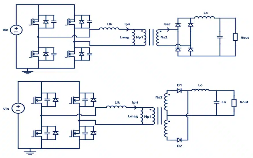
Phase-Shifted Full-Bridge (PSFB): Secondary full wave rectifier and center tap
Phase-shifted full-bridge (PSFP) converter topology is normally used for high-power applications, with the representation of leakage inductance on the primary side. For this kind of design, we can have two different design objectives:
- Aim at the lowest leakage possible to reduce losses in the design
- Aim for a specific leakage inductance to achieve Zero Voltage Switching (ZVS)
LLC Half bridge and Full bridge
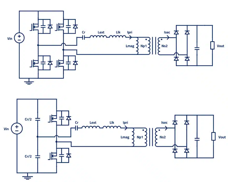
As in PSFB, LLC resonant converter will have the same magnetics, but for the resonant tank: used in High power applications and with the leakage inductance representation on the primary side. The LLC topology will have:
Input inductor (with two design options):
- Use it to achieve ZVS
- Try to reduce its value by using the leakage inductance
Output filter
- Controls sudden changes in the output
- Controls the voltage in the output
In LLC we need to design the resonant tank, which includes the external inductor, leakage inductance and magnetizing inductance. All these inductors, with the resonant capacitor, will influence the resonant frequency of our converter. We need to choose them wisely to make our converter work.
Push‑pull converters
The push‑pull converter is one of the earlier isolated topologies derived from the basic DC‑DC buck structure but using a center‑tapped transformer on the primary side. Two switches alternately drive each half of the primary winding, which allows bidirectional magnetization of the core and makes good use of core material at moderate power levels. The turns ratio provides galvanic isolation and voltage adaptation between input and output.
From the magnetics point of view, core flux balance is a key design concern in push‑pull converters. Any asymmetry in drive, device timing, or leakage can cause flux to accumulate in one direction, pushing the core toward saturation. As a result, the transformer often needs margin in core size and careful layout to minimize leakage inductance and stray resistances. Copper losses can be relatively high due to the center‑tapped primary and the resulting current distribution, which limits the practical power range compared with full‑bridge structures.
Half‑bridge PWM converters
The classic half‑bridge PWM converter uses two switches and either split DC bus capacitors or a bus divider network to generate a bipolar voltage across the transformer primary. Only half of the DC bus is applied at a time, so primary voltage is lower than in a full‑bridge, but it comes with reduced switch count and simpler gate drive. This makes half‑bridge converters attractive in the low‑ to mid‑power range where efficiency and cost must both be balanced.
For the transformer, the half‑bridge topology offers relatively good utilization of the core window, and the applied voltage waveform is well‑defined by the bus and duty cycle. The designer must account for any bus‑capacitor imbalance and ensure proper reset of the core flux within each switching cycle. Output inductors and EMI filters are similar in function to other hard‑switched PWM topologies, but their values will be driven by the chosen switching frequency and acceptable ripple current.
Full‑bridge PWM converters
The full‑bridge PWM topology uses four switches in an H‑bridge arrangement to apply the full DC bus across the transformer primary with alternating polarity. This configuration provides the highest effective primary voltage for a given bus, so it is used extensively at higher power levels where transformer size, copper losses, and efficiency are critical. The control can be simple fixed‑frequency PWM, or extended to more advanced modulation schemes such as phase shift.
Because the full‑bridge drives the transformer with the full bus voltage, the designer can often select a smaller core or higher turns ratio compared with half‑bridge or push‑pull alternatives. Magnetics design must still consider leakage inductance, stray capacitances, and winding arrangement to manage switching transitions and EMI. At high power levels, interleaved secondary windings, current‑doubler rectifiers, and planar magnetics are frequently combined with full‑bridge converters to reduce losses and improve thermal performance.
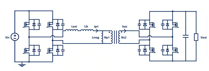
Dual Active Bridge DAB
With DAB as a bidirectional isolated DC/DC converter topology, we will be able to achieve bidirectional power transfer. Due to the topology design considerations, we will have an input inductor with the leakage inductance and the magnetizing inductance.
When we switch from one direction to the current inductor that we have on the primary side, will make the current change gradually.
Forward Converter
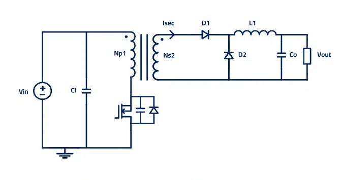
The forward converter is a DC/DC converter that uses a transformer to increase or decrease the output voltage (depending on the transformer ratio) and provide galvanic isolation for the load.
Used for low-power applications, it has an output filter to control the spikes and sudden changes at the output. Some further considerations for the forward converter:
- The output inductor makes the design not suitable for high-voltage applications compared to the flyback, but a good fit when high output currents are required.
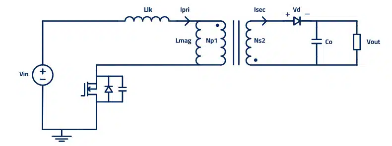
Flyback Converter
The flyback converter is a buck-boost converter with the inductor split to form a transformer, so that the voltage ratios are multiplied with an additional advantage of isolation. Flyback is used for low-power applications, and here the leakage inductance will be represented on the primary side. Further considerations:
- It provides isolation from mains voltages
- Since it doesn’t have an output inductor, as the forward topology does, we will have a high output ripple current. Therefore, Flybacks are more suitable for higher voltage applications instead of higher current.
Summary
All the topologies for transformers and the flyback converters are composed of several magnetics that influence every part of the design. The key to a successful outcome is to design them correctly.
How to Select the Right Transformer Topology for Your Power Converter
- Step 1 – Define your power level and voltage range
Identify your input and output voltage levels and the required output power. Low-power designs below approximately 100 W are well served by flyback or active-clamp flyback. Medium-power designs from 100 W to 500 W suit forward, push-pull, or half-bridge PWM converters. Above 500 W, choose between full-bridge PWM, PSFB, LLC resonant, or DAB depending on efficiency requirements and bidirectionality.
- Step 2 — Decide whether galvanic isolation is required
All topologies covered in this article are isolated. If isolation is not required, non-isolated buck, boost, or buck-boost structures may be simpler. If isolation is needed (mains safety, floating outputs, or long cable runs), proceed with one of the transformer-based topologies.
- Step 3 — Determine whether soft switching is necessary
If switching frequency must be high (above ~200 kHz) to reduce magnetic component size, or if efficiency targets are tight, select a topology that supports soft switching: PSFB (ZVS using leakage inductance), LLC resonant (ZVS inherent to resonant tank), active-clamp flyback (ZVS for the main switch), or DAB (ZVS achievable over a defined power range).
- Step 4 — Check whether bidirectional power flow is needed
If power must flow in both directions — for example in battery chargers with vehicle-to-grid capability, energy storage systems, or DC microgrids — the dual active bridge (DAB) is the standard choice. All other topologies discussed here are inherently unidirectional without additional circuitry.
- Step 5 — Design the magnetic components for the chosen topology
Once the topology is selected, design the transformer and any auxiliary magnetics (output inductors, resonant inductors, EMI filters) around its specific requirements: set leakage inductance deliberately for PSFB and LLC, manage flux balance for push-pull, size the magnetizing inductance correctly for LLC resonant tank operation, and select core material and winding arrangement suited to the operating frequency and thermal budget.
- Step 6 — Verify with simulation before prototyping
Simulate the chosen topology with realistic transformer models including magnetizing inductance, leakage inductance, and winding resistance. Confirm that ZVS is achieved over the intended load range, that peak switch voltages are within device ratings, and that the output ripple meets specification before committing to a prototype.
Conclusion
Transformer topology selection is one of the most consequential decisions in a power converter design, because it determines the number, type, and performance requirements of all magnetic components in the system. This article has reviewed nine isolated topologies — flyback, forward, push-pull, half-bridge PWM, full-bridge PWM, phase-shift full-bridge (PSFB), LLC resonant, dual active bridge (DAB), and active-clamp flyback — covering their power and frequency ranges, typical applications, and the key role played by transformers, inductors, and leakage inductance in each case.
Across all topologies, a consistent theme emerges: the magnetic components — transformer, magnetizing inductance, leakage inductance, and output inductor — are not simply passive elements but active design variables that shape converter efficiency, switching behavior, EMI signature, and thermal profile. Choosing between hard-switched and soft-switched topologies, between flyback-derived and bridge-derived structures, or between unidirectional and bidirectional power flow ultimately comes down to correctly specifying and designing these magnetics for the target application.
For design engineers working with passive components, understanding which topology is being implemented — and why — provides the essential context for sizing cores, selecting winding configurations, specifying filter inductors, and managing parasitic effects. Each topology covered in this article has dedicated in-depth resources linked within the text for further study.
FAQ
A flyback converter stores energy in the transformer during the switch-on time and releases it to the output during switch-off, making the transformer act as a coupled inductor — no separate output inductor is needed. A forward converter transfers energy directly to the output while the primary switch is on, requiring a separate output inductor and a core reset mechanism. Flyback is preferred for higher output voltages and lower power; forward converters suit higher output currents.
In hard-switched topologies (forward, half-bridge PWM, full-bridge PWM) leakage inductance generates unwanted voltage spikes at switch turn-off, which must be clamped or dissipated. In soft-switched designs (PSFB, LLC) it is deliberately engineered into the transformer or added externally as a resonant inductor to enable zero-voltage switching (ZVS), directly improving efficiency. In the dual active bridge (DAB) topology, leakage inductance is the primary element controlling bidirectional power transfer.
At power levels above 500 W, the most commonly used isolated topologies are the phase-shift full-bridge (PSFB), LLC resonant full-bridge, and dual active bridge (DAB). PSFB and LLC offer high efficiency through soft switching and are widely used in server, telecom, and EV charging supplies. DAB is preferred when bidirectional power flow is required, such as in battery storage systems and vehicle-to-grid applications. Full-bridge PWM is also used where simplicity and wide duty-cycle range are priorities over soft-switching losses.
The LLC resonant converter operates its switches at or near zero-voltage switching across a wide load range, which significantly reduces switching losses compared with a hard-switched full-bridge PWM. This allows LLC converters to run at higher switching frequencies (up to several hundred kHz or beyond 1 MHz with GaN devices), enabling smaller magnetic components. The transformer magnetizing inductance forms part of the resonant tank, so the magnetics are tightly integrated with the control strategy, requiring careful design but delivering very high efficiency in adapters, data-centre power supplies, and EV on-board chargers.
The push-pull topology becomes difficult to scale to high power because it uses only two switches while applying the full DC bus voltage across each half of the center-tapped primary, requiring devices rated at twice the bus voltage. At high power levels this voltage stress and the risk of flux imbalance (which can drive the core into saturation) make the full-bridge or half-bridge topologies more practical choices. Push-pull remains attractive in low-voltage, moderate-power DC-DC applications — such as automotive and battery-powered systems — where its simpler gate drive and efficient core utilization are advantageous.
References
- Blázques, P. (2023) — original Frenetic / Passive Components Blog article
- Passive Components Blog – Transformer Design Optimization for Power Electronics
- Passive Components Blog — Transformer Calculation: Losses, Parasitics and Applications
- Passive Components Blog — Inductors: Inductance, Impedance and Losses
- Passive Components Blog — RF Inductors and Filters
- Erickson & Maksimovic (2020) — Fundamentals of Power Electronics, 3rd ed., Springer
- Kazimierczuk (2015) — High-Frequency Magnetic Components, 2nd ed., Wiley
- Mohan, Undeland & Robbins (2002) — Power Electronics: Converters, Applications, and Design, 3rd ed., Wiley
- Liu, J. (2006) — Modelling and Design of the LLC Resonant Converter, IEEE Transactions on Power Electronics
- De Doncker, Divan & Kheraluwala (1991) — DAB soft-switched DC/DC converter, IEEE Transactions on Industry Applications 27(1), 63–73
- Frenetic Online — Magnetic Component Design Tool (frenetic.ai)


