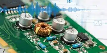
This presentation from Würth Elektronik provides brief overview of transient suppression guide for beginners.
As the number of electronic devices connected to public power grids and networked communications rises, the risk of mutual interference caused by electromagnetic interference (EMI) grows significantly. Effective transient suppression and EMI filtering are now critical in maintaining functional reliability and device safety, particularly across wired interfaces.
This presentation synthesizes the principles and advanced techniques of transient suppression with a focus on how to implement robust filter solutions for mains power, asymmetrical signal lines, and symmetrical signal interfaces in modern electronics.
Key Takeaways
- As electronic devices increase, so does the need for effective transient suppression and EMI filtering.
- Key topics include fundamental concepts of EMI, interface characterization, and compliance with EMC regulations.
- Advanced design techniques for filters, specifically for asymmetrical and symmetrical signal interfaces, are discussed.
- Practical tips for component selection and integration into various applications ensure long-term performance and safety.
1. Fundamentals of EMI and Transient Suppression
Electromagnetic interference (EMI) arises from unintentional electromagnetic emissions and can severely affect the performance of electronic equipment. A primary source includes rapidly increasing numbers of interconnected and sensitive devices, creating both conducted and radiated noise. Transient suppression refers to protecting circuits against short-duration high-voltage spikes, often from switching events, lightning, or electrostatic discharge (ESD).
1.1 Characterization of Interfaces
- Grid Interfaces: These are connections between consumer equipment and the power grid (e.g., 230VAC mains). They are especially sensitive to conducted EMI and require filters to prevent disturbances in both directions—protection of equipment from grid disturbances and vice versa.
- Asymmetrical Signal Interfaces: A single data line with a ground return. They are more vulnerable to emissions and have higher susceptibility to interference than balanced (symmetrical) lines due to “unbalanced” current paths, making robust filtering especially important.
- Symmetrical Signal Interfaces: (e.g., RS-485, USB differential pairs, CAN bus). These carry signals over two wires with equal impedance to a reference, improving resistance to common-mode noise, but can still be disturbed by high-energy transients and radiated EMI.
1.2 EMC Regulations and Practical Importance
EMC regulations (IEC, CISPR, FCC) set thresholds for emissions and immunity. Properly implemented transient suppression ensures:
- Device compliance with legal EMC limits
- Protection against catastrophic failure or data loss
- Long equipment lifetime and reduced maintenance
2. Advanced EMI Filter Design for Asymmetrical Signal Interfaces
2.1 Advanced PI Filter Implementation
A PI filter for an unbalanced signal line consists of an input impedance (e.g., ferrite bead L1), a shunt capacitor (C, Z1), and a parallel branch for transient protection (varistor/TVS, Z2A/B). The design goals include:
- Attenuation of Harmonics: Signal harmonics and noise, e.g., for a 5 MHz square wave (data line), 5th harmonic is 25 MHz. Select the ferrite so its impedance at that frequency is less than 1/10 of the line impedance (i.e., <9 Ω for 90 Ω line) to avoid altering data integrity.
- Capacitor Sizing: For ≥10 dB attenuation at 500 MHz, calculate reactance for C:
- ,select C accordingly, allowing for PCB trace and connector parasitics. For the example, this yields ~7.5 pF (rounded to 10 pF).
- Transient Suppression Selection: Varistors effectively clamp surges thanks to high capacitance and energy-handling capabilities (better than many TVS diodes in data applications), but their capacitance must match the filtering need (~200 pF in the circuit example).
- Energy Calculation: For a surge event, calculate energy absorption e.g., for a 0.5 kV pulse, 20 µs, peak current 11.6 A:
- E = 2×V_{BR}×I_{clamp,max}×t_{pulse}
2.2 Component Sizing and Selection
| Component | Selection Criteria | Example Part |
|---|---|---|
| Inductor / Ferrite Bead (L1) | Impedance < 1/10 system impedance at 5th harmonic. For a 5 MHz signal, at 25 MHz: < 9 Ω. | WE-CBF 74279273 |
| Capacitor (Z1) | Attenuation ≥ 10 dB at 500 MHz. Calculation: C = 1 2πfZ_1 (For 500MHz, Z1=42Ω, C ≈ 7.5pF) | MLCC 10pF / 25V, NPO ceramic (WCAP CSGP) |
| Transient Protection Device (Z2A) | Surface mount multilayer varistor, voltage rating ≥ 115% of system VDC | WVS 5.5V, Capacitance 200pF |
| Additional Capacitance (Z2B) | Supplement total filter capacitance to reach ~250pF If varistor capacitance is sufficient, additional capacitor may be omitted. | MLCC 47pF (if required) |
2.3 Supply Voltage Line Filter Considerations
- Use decoupling capacitor (100nF X7R) with sufficient voltage rating.
- Ferrite bead with current rating > 2× max supply current.
- Filter impedance should be high across the 30 MHz – 1 GHz range.
2.4 Practical Tips and Pitfalls
- Avoid excessively high filter capacitance, as this can load the driver and cause signal distortion.
- Redundant filtering on supply lines: Use X7R MLCCs for stability; size ferrite beads above twice the application current.
- Account for board layout—keep high-frequency filter elements close to the interface connector and minimize ground impedance to reduce bypass path resistance.
- Use simulation tools (e.g., Würth RED Expert) for real-world impedance and frequency response prediction.
3. Filter Design for Symmetrical (Balanced) Signal Interfaces
3.1 Differential and Common Mode Filtering
Differential Mode filters ensure desired signals pass with minimal loss, while Common Mode chokes suppress noise that appears in phase on both wires.
- Choke Selection: For a 90 Ω system (USB, CAN), select a common mode choke with ZDM < 9 Ω at the signal band’s highest frequency but maximize ZCM at EMI frequencies (e.g., 100 MHz+).
- Filter Capacitors and Damping: Shunt capacitors (2.2–10 pF) and series resistors (3–10 Ω) are dimensioned based on measured signal quality/reflection. For USB 2.0, use 4.7 pF and 3.3 Ω as a reliable starting point.
- Transient Suppression: Select TVS diodes or arrays (low capacitance types) matched to data-line applications to avoid excess signal path loading—critical for high-speed buses.
| Component | Selection Criteria | Example Part |
|---|---|---|
| Common Mode Choke (L1) | ZDM (differential) < Zsystem/10 across bandwidth. ZCM (common) as high as possible at interference frequencies. | WE CNSW 744233900 |
| Capacitors (Z1, Z2) | 2.2–10pF for high-frequency attenuation (USB 2.0 typical: 4.7pF) | WCAP CSGP |
| Resistors (Z5, Z6) | 3–10Ω, set by board measurement for reflection/impedance matching | RF precision types, 3.3Ω typical |
| TVS Diode Array | Fast response, suitable voltage, low capacitance for data lines | Wii TVS diode 824136 |
3.2 Example — USB 2.0 Protection Strategy
- Bandwidth & Impedance: Approximately 240 MHz, 90 Ω.
- Inductor (L1): Choose based on RedExpert or similar tool, verify ZCM at 240 MHz meets spec without exceeding 1/10 Zsystem in DM.
- TVS Diode Array: Use models with capacitance ≤ 1 pF per line at standard signal levels to avoid bandwidth penalty.
- Chassis Bonding: Use direct, low-impedance ground connections. Use decoupling capacitors for coupling high-frequency noise to shield/housing rather than signal ground.
3.3 System Integration Challenges
- Mixed-Signal Issues: Balanced lines adjacent to unbalanced supplies can couple noise—layout, and ground referencing must be carefully engineered.
- High-Frequency Stability: Use of compact, RF-suitable resistors and creative PCB design to avoid stubs and maintain controlled impedance.
- Ferrite and Choke Placement: Place components as close as possible to the signal entry/exit for maximum EMI attenuation.
4. Advanced Power Line Filter and Surge Suppression
4.1 Safety Design for AC Mains Filters
Filters for power mains (230VAC) must meet safety and EMC regulations. Sizing Y/X capacitors is driven by leakage current limits and required attenuation.
Further, it’s essential to use current-compensated chokes, ensure PCB and housing ground is low-impedance, and observe EMC/IEC surge test requirements for component sizing and selection.
- Leakage Limitations: Calculate max Y-capacitance for permissible leakage current per standards (e.g., 2.66 mA in PE, yielding ~33 nF).
- Common Mode Choke: Use high inductance (>10 mH for sinusoidal, 1–10 mH for switchers). Choose current-rating for worst-case load and temperature.
- Filter Corner Frequency: Design for required attenuation at 150 kHz (20 dB DM, 40 dB CM). Use the measured frequency response to fine-tune X and Y capacitor selection. See the chart below.
| Mode | Target Attenuation (dB) | Capacitor Value | Typical Result |
|---|---|---|---|
| Differential | 20 @ 150 kHz | 2.2 µF (X-cap) | ≥32 dB (measured) |
| Common Mode | 40 @ 150 kHz | 14 nF (Y-cap) | ≥43 dB (measured) |
| Parameter | Calculation | Example Value |
|---|---|---|
| Maximum Permissible Leakage Current | Safety value (example: 2.66 mA) | 2.66 mA |
| Max. Y Capacitor Value | C=I_{leak}2\pi f_{mains} V_{max} | 33 nF |
| Common Mode Choke Inductance | Depends on load, waveform, ambient temperature | 10 mH for sinusoidal load |
| X Capacitor Value | Attenuation goals (e.g., ≥20dB at 150kHz, CX ≈ 2.2 μF) | 2.2 μF |
| Surge Protection Varistor | Rated for > maximum voltage + safety margin (e.g., 230VAC × 1.15 = 264.5VAC; use 300V rating) | Disk varistor VD, 300V |
4.2 Surge Protection Calculations and Approaches
- Surge Test Standard: IEC/EN61000-4-5 — pulse 2 kV, 20 µs, source impedance 2 Ω. Varistor must clamp surge below breakdown/peak current ratings.
- Sizing Varistors: Use 15% margin above maximum mains; e.g., for 230 VAC:
- Max operating voltage = 230 V × 1.15 ≈ 265 V; select 300 V varistor
- Calculate absorbed energy: W_{max} = 2*V_{BR}*I_{peak}*t_{pulse} (e.g., 11 J for the specified pulse)
- Continuous power loss for repeated surges: P = W_{max}T
- Additional Attenuation (above 10 MHz): Use additional X/Y capacitors strategically located for high-frequency harmonic suppression, but ensure safety with respect to creepage, clearance, and leakage.
4.3 Practical Integration and Compliance
- All filtering and protective components must be safety-agency approved (e.g., UL, VDE) and rated for worst-case scenario.
- Ground connections for common-mode chokes and Y capacitors must be as low impedance as possible—preferably metal chassis or thick copper pours.
- Test compliance by measuring both conducted and radiated emissions with a certified EMC analyzer after installation.
Conclusion
Modern electronic designs demand increasingly sophisticated solutions for transient suppression and EMI filtering. By applying the principles, equations, and selection guidelines discussed—engineers can ensure robust protection of signal integrity and power quality at every device interface.
The outlined filter designs, component tables, and safety calculations are adaptable across application scenarios from signal transmission lines to mains power filtering—supporting compliance, reliability, and long-term performance. For application notes, datasheets, and technical support, consult component manufacturers and current EMC standards tailored to your region and industry sector.
FAQ
Transient suppression protects electronic devices against short, high-voltage spikes by using special components like varistors and TVS diodes. It helps maintain the safety and reliability of devices affected by EMI and surges.
Grid interfaces (e.g., 230V mains), asymmetrical signal interfaces (single data line), and symmetrical signal interfaces (differential pairs) all benefit from tailored EMI filtering and transient suppression.
Key components include ferrite beads, common mode chokes, MLCC and X/Y ceramic capacitors, varistors, and TVS diode arrays. Their correct selection and sizing are critical for effective protection.
Capacitance value is determined based on the desired attenuation at a specific frequency using the formula: capacitance = 1/(2π×frequency×impedance). This ensures effective filtering at the target frequency without signal distortion.
Sizing is done using standards like IEC/EN61000-4-5, considering maximum pulse voltage, current rating, and energy absorption (e.g., 11 Joules for a 2kV surge). A safety buffer above expected voltage is always included.
ll components should be located as close as possible to the signal or power entry point, with short, low-impedance ground paths to maximize their effectiveness, especially in high-frequency applications.
How to Design an EMI and Transient Suppression Filter Circuit
- Identify interface type:
Determine whether the interface is mains, unbalanced signal, or balanced signal.
- Calculate target attenuation:
For signal lines, find the highest relevant frequency (harmonics). For power lines, follow regulatory attenuation requirements (e.g., 20dB at 150kHz for differential mode).
- Select components:
Ferrite beads/chokes for inductive filtering
MLCC/X7R capacitors for high-frequency attenuation
Varistors/TVS diodes for transient suppression - Calculate capacitance and impedance:
Use the formula: C = 1/(2πfZ). Make sure the resulting values won’t distort the useful signal.
- Place and route components:
Position all filter and protection devices as close to the connector/housing entry as possible. Use thick ground pours or metal chassis for reference connections.
- Verify by simulation and measurement:
Use circuit simulators or specialized EMC tools (like Würth RED Expert) and validate compliance against real-world standards using a spectrum analyzer.
- Review and iterate:
After board assembly, measure emissions and immunity. Adjust component values or placement to optimize for lowest EMI and highest transient protection.


