











Passive Components Blog
No Result
View All Result
  • Home
  • NewsFilter
    • All
    • Aerospace & Defence
    • Antenna
    • Applications
    • Automotive
    • Capacitors
    • Circuit Protection Devices
    • electro-mechanical news
    • Filters
    • Fuses
    • Inductors
    • Industrial
    • Integrated Passives
    • inter-connect news
    • Market & Supply Chain
    • Market Insights
    • Medical
    • Modelling and Simulation
    • New Materials & Supply
    • New Technologies
    • Non-linear Passives
    • Oscillators
    • Passive Sensors News
    • Resistors
    • RF & Microwave
    • Telecommunication
    • Weekly Digest

    Exxelia Offers 1200V Capacitors and Magnetics for 800V Aerospace Platforms

    Wk 28 Electronics Supply Chain Digest

    Bourns Introduces Automotive BMS Signal Transformer with Integrated Common Mode Chokes

    Itelcond Introduces High‑Voltage Aluminium Capacitors for Modern IGBT DC‑links

    Bourns Introduces Automotive Shielded Power Inductors for Compact DC‑DC Converters

    EMC Design Fundamentals: Safe Use of Varistors and Common Mode Chokes in Mains and Data-Line Filters

    Murata Unveils Lead Disc Ceramic Capacitors for Automotive Safety and EMI Suppression

    SCHURTER Releases Intelligent Three‑Terminal Fuses for Safer Li‑ion Battery Systems

    Can Copper Conductive Inks Displace Silver in Hybrid Electronics?

    Trending Tags

    • Ripple Current
    • RF
    • Leakage Current
    • Tantalum vs Ceramic
    • Snubber
    • Low ESR
    • Feedthrough
    • Derating
    • Dielectric Constant
    • New Products
    • Market Reports
  • VideoFilter
    • All
    • Antenna videos
    • Capacitor videos
    • Circuit Protection Video
    • Filter videos
    • Fuse videos
    • Inductor videos
    • Inter-Connect Video
    • Non-linear passives videos
    • Oscillator videos
    • Passive sensors videos
    • Resistor videos

    EMC Design Fundamentals: Safe Use of Varistors and Common Mode Chokes in Mains and Data-Line Filters

    Ferrite versus Nanocrystalline Power Inductor Cores: Turns, Gap and Size

    KYOCERA AVX Presents Antenna Integrator Studio Tutorial for Antenna Placement and RF Design

    Power Design Simulation Tools for Faster Inductor Selection and Loss Optimization

    EMC‑Compliant PCB and Connector Design Guidelines

    Why Isolated DC/DC Power Supplies Fail Late, Würth Elektronik Podcast

    Designing 800 V DC EMC Filters: Calculation, Simulation and Measurement

    Current Sense Transformer Datasheet and Design‑in Guide

    Designing a USB Type‑C Flyback Planar Transformer with Frenetic’s Planar Tool

    Trending Tags

    • Capacitors explained
    • Inductors explained
    • Resistors explained
    • Filters explained
    • Application Video Guidelines
    • EMC
    • New Products
    • Ripple Current
    • Simulation
    • Tantalum vs Ceramic
  • Knowledge Blog
  • Dossiers
    • AI Hardware Dossier
    • Power Converter Dossier
    • Automotive Dossier
    • Capacitor Dossier
    • Resistor Dossier
    • Inductor Dossier
    • Circuit Protection Dossier
  • Suppliers
    • Who is Who
  • PCNS
    • PCNS 2025
    • PCNS 2023
    • PCNS 2021
    • PCNS 2019
    • PCNS 2017
  • Events
  • Home
  • NewsFilter
    • All
    • Aerospace & Defence
    • Antenna
    • Applications
    • Automotive
    • Capacitors
    • Circuit Protection Devices
    • electro-mechanical news
    • Filters
    • Fuses
    • Inductors
    • Industrial
    • Integrated Passives
    • inter-connect news
    • Market & Supply Chain
    • Market Insights
    • Medical
    • Modelling and Simulation
    • New Materials & Supply
    • New Technologies
    • Non-linear Passives
    • Oscillators
    • Passive Sensors News
    • Resistors
    • RF & Microwave
    • Telecommunication
    • Weekly Digest

    Exxelia Offers 1200V Capacitors and Magnetics for 800V Aerospace Platforms

    Wk 28 Electronics Supply Chain Digest

    Bourns Introduces Automotive BMS Signal Transformer with Integrated Common Mode Chokes

    Itelcond Introduces High‑Voltage Aluminium Capacitors for Modern IGBT DC‑links

    Bourns Introduces Automotive Shielded Power Inductors for Compact DC‑DC Converters

    EMC Design Fundamentals: Safe Use of Varistors and Common Mode Chokes in Mains and Data-Line Filters

    Murata Unveils Lead Disc Ceramic Capacitors for Automotive Safety and EMI Suppression

    SCHURTER Releases Intelligent Three‑Terminal Fuses for Safer Li‑ion Battery Systems

    Can Copper Conductive Inks Displace Silver in Hybrid Electronics?

    Trending Tags

    • Ripple Current
    • RF
    • Leakage Current
    • Tantalum vs Ceramic
    • Snubber
    • Low ESR
    • Feedthrough
    • Derating
    • Dielectric Constant
    • New Products
    • Market Reports
  • VideoFilter
    • All
    • Antenna videos
    • Capacitor videos
    • Circuit Protection Video
    • Filter videos
    • Fuse videos
    • Inductor videos
    • Inter-Connect Video
    • Non-linear passives videos
    • Oscillator videos
    • Passive sensors videos
    • Resistor videos

    EMC Design Fundamentals: Safe Use of Varistors and Common Mode Chokes in Mains and Data-Line Filters

    Ferrite versus Nanocrystalline Power Inductor Cores: Turns, Gap and Size

    KYOCERA AVX Presents Antenna Integrator Studio Tutorial for Antenna Placement and RF Design

    Power Design Simulation Tools for Faster Inductor Selection and Loss Optimization

    EMC‑Compliant PCB and Connector Design Guidelines

    Why Isolated DC/DC Power Supplies Fail Late, Würth Elektronik Podcast

    Designing 800 V DC EMC Filters: Calculation, Simulation and Measurement

    Current Sense Transformer Datasheet and Design‑in Guide

    Designing a USB Type‑C Flyback Planar Transformer with Frenetic’s Planar Tool

    Trending Tags

    • Capacitors explained
    • Inductors explained
    • Resistors explained
    • Filters explained
    • Application Video Guidelines
    • EMC
    • New Products
    • Ripple Current
    • Simulation
    • Tantalum vs Ceramic
  • Knowledge Blog
  • Dossiers
    • AI Hardware Dossier
    • Power Converter Dossier
    • Automotive Dossier
    • Capacitor Dossier
    • Resistor Dossier
    • Inductor Dossier
    • Circuit Protection Dossier
  • Suppliers
    • Who is Who
  • PCNS
    • PCNS 2025
    • PCNS 2023
    • PCNS 2021
    • PCNS 2019
    • PCNS 2017
  • Events
No Result
View All Result
Passive Components Blog
No Result
View All Result

Understanding Inductors With Gapped Cores

22.5.2026
Reading Time: 8 mins read
A A

Inductors are fundamental components in electronic circuits, used extensively for their ability to store energy in a magnetic field. The design and selection of inductors can significantly impact the performance of a circuit, especially in power supply and radio-frequency applications. One critical aspect of inductor design is the use of gapped cores, which introduces an air gap into the magnetic path of the inductor’s core. This blog post delves into the nuances of air-core versus magnetic-core inductors, the concept of gapped cores, and the implications of introducing an air gap in inductors.

Air-Core vs. Magnetic-Core Inductors

The primary distinction between air-core and magnetic-core inductors lies in the presence of a magnetic material in the core. Air-core inductors do not contain a ferromagnetic core; instead, they rely on the air itself to form the magnetic circuit. This design is advantageous at high frequencies where core losses in magnetic materials can become significant. On the other hand, magnetic-core inductors use materials like iron or ferrite to concentrate the magnetic field, resulting in higher inductance values for a given size and number of turns.

RelatedPosts

Planar vs Conventional Transformer: When it Make Sense

Why Power Inductors Use a Ferrite Core With an Air Gap

Thermal Modeling of Magnetics

Gapped Core Inductors: An Overview

A gapped core inductor incorporates a deliberate air gap in the magnetic core. This gap is introduced to manage the core’s saturation and improve its current-handling capability. By adding an air gap, the inductor’s inductance decreases, but its ability to handle higher currents without saturating increases. The air gap also contributes to stabilizing the inductance against variations in the core material’s permeability, making the inductor’s performance more predictable.

Analyzing the Gapped Core

The introduction of an air gap affects several parameters of an inductor. It reduces the effective permeability of the core, which is a measure of the core’s ability to support the formation of a magnetic field. A lower effective permeability means that the inductor will have a lower inductance value for the same number of turns and core area. However, this also means that the inductor can tolerate a higher current before the core material saturates.

Effective Permeability of Gapped Core

Effective permeability is a critical factor in designing gapped core inductors. It represents the average permeability of the core material and the air gap. The presence of the air gap reduces the effective permeability significantly, as air has a much lower permeability than ferromagnetic materials. This reduction in effective permeability is beneficial in applications where a stable inductance value is crucial, as it makes the inductor less sensitive to changes in the core material’s properties.

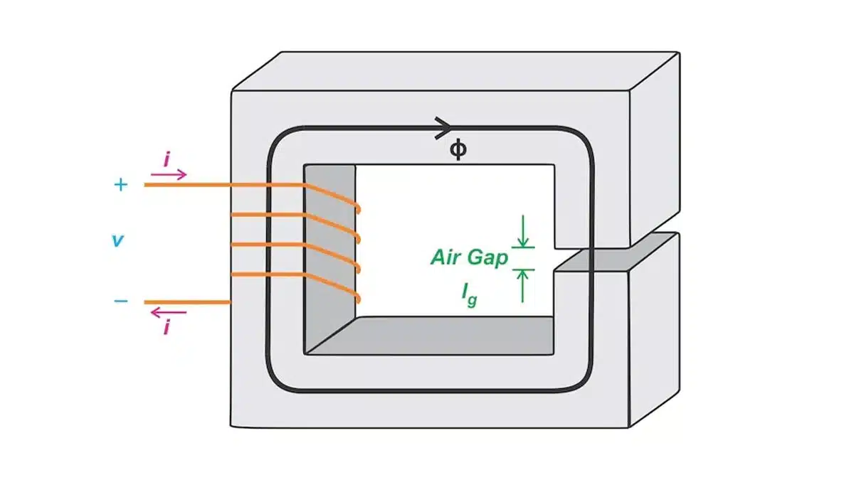
Based on the featured image to see how the air gap influences different inductor parameters. Assume that:

  • The core has relative permeability μc and mean length lc.
  • The gap has a relative permeability of unity and a length of lg.
  • The cross-sectional areas (A) of the core and the air gap are equal.

If the permeability of the core is much larger than unity (μc ≫ 1), a gapped core has an effective relative permeability of:

μeff ≈ lc/lg

where:

lc is the mean length of the core

lg is the gap length.

When lc = 100lg, for example, the gapped core has an effective relative permeability of 100. The important takeaway here is that the gap dominates the core behavior as long as μc ≫ 1.

Impact of Air Gap on Inductance and Material Permeability

The air gap’s impact on inductance is twofold: it reduces the inductance value and decreases the sensitivity of the inductance to the core material’s permeability. This desensitization is particularly useful in environments with temperature fluctuations or in applications where the inductor is subjected to varying currents, which can otherwise alter the core’s permeability and, consequently, the inductance.

Since the gap lowers the effective relative permeability of the core, it’s no surprise that adding a gap also lowers the inductance of the structure. Another way to reach the same result is by applying the definition of inductance. We know that inductance is defined as:

L = nΦ/i

we find the inductance of the gapped core to be:

L = n2/(Rmc + Rmg)

The air gap increases the total reluctance and decreases the inductance. Despite this apparent decrease, gapped cores offer three important advantages:

  • They reduce sensitivity to material permeability.
  • They increase the saturation current.
  • They increase the stored energy.

Without an air gap, the inductance is directly proportional to the core material permeability, which changes with temperature and is a nonlinear function of the applied magnetic field intensity. This makes it hard to precisely control the inductance.

Now consider a gapped core. Since the reluctance of the air gap is much larger than that of the core material:

L ≈ n2/Rmg = n2/(lg/μ0A) = n2μ0A/lg

From the above, we can see that a gapped core’s inductance depends mainly on the gap properties (A and lg). Since the permeability of air (μ0) is constant, it’s possible to adjust the gap length to build well-controlled inductances that are less sensitive to variations in permeability.

Increasing Saturation Current and Stored Energy

By introducing an air gap, the saturation current of the inductor increases. This is because the air gap requires a higher magnetomotive force (current times the number of turns) to achieve the same flux density in the core as would be needed without the gap. As a result, the inductor can handle higher currents without the core material reaching saturation. Additionally, the air gap allows the inductor to store more energy, which is advantageous in power applications where energy storage is essential.

When a gap is introduced into the core, the effective reluctance increases. A larger current is thus required to saturate the core. Let’s calculate the maximum current that the inductor can handle without reaching saturation.

the B value of a gapped inductor is given by:

B = ni/(Rmc + Rmg)Ac

where Ac is the cross-sectional area of the core. The current at the onset of saturation, therefore, is:

Isat = BsatAc*(Rmc+Rmg)/n

where Bsat is the saturation magnetic flux density. The air gap increases the effective reluctance, and hence the saturation current, of the core.

Choosing Gap Length and Number of Turns

Selecting the appropriate gap length and number of turns is a balancing act. A larger gap can increase the inductor’s current-handling capability but at the expense of reduced inductance. Conversely, increasing the number of turns can compensate for the reduced inductance due to the air gap but may result in a physically larger inductor. Engineers must consider these trade-offs in the context of their specific application requirements.

We saw that the air gap increases the saturation current but lowers the inductance. To compensate for the loss of inductance due to the air gap, we can increase the coil’s number of turns (n). This increases the magnetic field generated by the coil, restoring the inductance to the desired value.

Assuming that the gap reluctance is much greater than that of the core:

L ≈ n2/Rmg

and:

B ≈ ni/RmgAc

Increasing the value of n causes both the inductance (L) and the magnetic flux density (B) to increase as well. However, L is proportional to n2 and B is proportional to n. The inductance therefore grows faster than the flux density when n is increased.

Conclusion: The Advantages of Air Gapped Inductors

Air gapped inductors offer several advantages, including increased saturation current, reduced sensitivity to core material variations, and enhanced energy storage capabilities. These benefits make them suitable for a wide range of applications, from power supplies to RF circuits. Understanding the interplay between the air gap, inductance, and saturation current is crucial for optimizing inductor design for specific applications.

In summary, gapped core inductors are a versatile and robust solution for managing the performance of inductors in various electronic applications. Their ability to maintain stability under different operating conditions makes them an invaluable component in the design of reliable and efficient electronic systems.

All of these advantages are achieved at the expense of a smaller inductance. However, by appropriately choosing the gap length and the number of turns, we can restore the desired inductance while avoiding core saturation. This technique is commonly used to design inductors for power electronics applications.


Related

Recent Posts

Exxelia Offers 1200V Capacitors and Magnetics for 800V Aerospace Platforms

22.7.2026
16

Bourns Introduces Automotive BMS Signal Transformer with Integrated Common Mode Chokes

17.7.2026
29

Bourns Introduces Automotive Shielded Power Inductors for Compact DC‑DC Converters

16.7.2026
58

EMC Design Fundamentals: Safe Use of Varistors and Common Mode Chokes in Mains and Data-Line Filters

16.7.2026
88

Square-Wave Harmonics and RMS Currents in Power Converters

14.7.2026
67

In the Age of AI, Every Watt Counts: Implications for Components

13.7.2026
101

RF Filters and Passive Components Enabling the 7 Missile RF Subsystems

9.7.2026
65

Ferrite versus Nanocrystalline Power Inductor Cores: Turns, Gap and Size

9.7.2026
91

YAGEO Presents NANOMET Soft Magnetic Cores for High‑Density Power Conversion

8.7.2026
155

Upcoming Events

Jul 28
8:00 - 11:00 CEST

Post Procurement Testing of EEE Components for LEO Space Applications

Jul 29
17:30 - 18:30 CEST

To Ferrite or to Nanocrystalline in Transformer Design

Sep 29
16:00 - 17:00 CEST

Cybersecurity 2026

View Calendar

Popular Posts

  • Boost Converter Design and Calculation

    0 shares
    Share 0 Tweet 0
  • Buck Converter Design and Calculation

    0 shares
    Share 0 Tweet 0
  • YAGEO Announces July 2026 Capacitor Price Increase

    0 shares
    Share 0 Tweet 0
  • Flyback Converter Design and Calculation

    0 shares
    Share 0 Tweet 0
  • LLC Resonant Converter Design and Calculation

    0 shares
    Share 0 Tweet 0
  • MLCC and Ceramic Capacitors

    0 shares
    Share 0 Tweet 0
  • MLCCs in the Age of AI: Q2 2026 Market Tightness

    0 shares
    Share 0 Tweet 0
  • Earthing Systems and IEC Classification Explained

    0 shares
    Share 0 Tweet 0
  • Nvidia Vera Rubin: Why One AI Rack Needs So Many More MLCC Capacitors

    0 shares
    Share 0 Tweet 0
  • Dual Active Bridge (DAB) Topology

    0 shares
    Share 0 Tweet 0

Newsletter Subscription


Passive Components Blog

© EPCI - Leading Passive Components Educational and Information Site

  • Home
  • Privacy Policy
  • EPCI Membership & Advertisement
  • About

No Result
View All Result
  • Home
  • Knowledge Blog
  • Dossiers
  • PCNS

© EPCI - Leading Passive Components Educational and Information Site

This website uses cookies. By continuing to use this website you are giving consent to cookies being used. Visit our Privacy and Cookie Policy.










