





Magnetic core materials determine the achievable inductance, saturation margin, power loss, thermal performance and EMI behaviour of inductors and transformers. This guide explains material families, permeability, core shapes, air gaps, winding construction and loss estimation, with practical selection and qualification guidance for design engineers and component engineers working on power conversion, filtering and sensing.
The article brings together magnetic-core fundamentals and practical construction guidance, including educational material originally contributed by Pablo Blázquez of Frenetic. Its discussion of DC premagnetization, relaxation and transverse-flux losses is supported by the technical publications and Jonas Mühlethaler webinar listed in References. [6–8]
Key Takeaways
Select a core and winding as a complete magnetic assembly. Material names and nominal permeability values alone do not establish application suitability.
- The main soft-magnetic material families are electrical steel, iron and alloy powder cores, ferrites, amorphous alloys and nanocrystalline alloys. Each offers a useful operating window rather than universal superiority.
- Permeability depends on excitation, frequency, temperature, DC bias and mechanical stress. The effective permeability of a component also depends on its magnetic path and gaps.
- A discrete or distributed gap can support energy storage by reducing effective permeability, but it does not increase the material’s intrinsic saturation flux density. Discrete gaps also create fringing fields.
- Core loss and winding loss must be assessed separately and then combined thermally. Conductor type, winding placement, leakage fields and gap location can change the optimum material and geometry.
- Steinmetz models require consistent flux definitions and coefficients fitted to the operating range. Waveform, DC premagnetization, relaxation and transverse flux can make simple estimates inaccurate.
- Final selection requires a controlled component specification and prototype validation across electrical, thermal, mechanical and insulation requirements, including start-up and relevant abnormal conditions.
What a Magnetic Core Does
A winding carrying current creates magnetic field strength H, measured in amperes per metre, and magnetic flux density B, measured in teslas. A soft-magnetic core can increase flux linkage and inductance for a given winding and magnetizing current, enabling more compact inductors, transformers and filtering components. The trade-offs include saturation, magnetic loss and additional construction constraints. [1]
The electrical function matters. A storage inductor intentionally supports magnetizing current and stores energy; a power transformer transfers energy through coupled windings; a common-mode choke suppresses common-mode excitation; and a current transformer reproduces an AC current with specified accuracy. These functions do not require the same permeability, gap or loss characteristics.
Voltage, turns and flux excursion
For N turns linking the main core flux through effective cross-sectional area Ae, in square metres, Eq. (1) relates the induced winding voltage v(t), in volts, to the rate of change of B with time t, in seconds. The sign convention uses the winding voltage polarity associated with increasing linked flux. [6]
For an approximately constant induced voltage Von during an interval ton, Eq. (2) gives the corresponding flux-density change ΔB. Use the voltage associated with the main linked flux, accounting for winding-resistance and leakage-voltage drops where they materially affect the result.
Equation (2) gives a change in flux density, not the absolute peak flux or initial operating point. Include DC bias, remanence, reset behaviour, tolerances and transient conditions when assessing saturation margin. In periodic transformer operation, the linked flux must return to its intended starting value each cycle.
The calculated flux excursion must also be checked against loss data at the operating temperature. A core can overheat while remaining below saturation; conversely, acceptable average loss does not prove adequate transient saturation margin.

Magnetic Quantities and B–H Curves
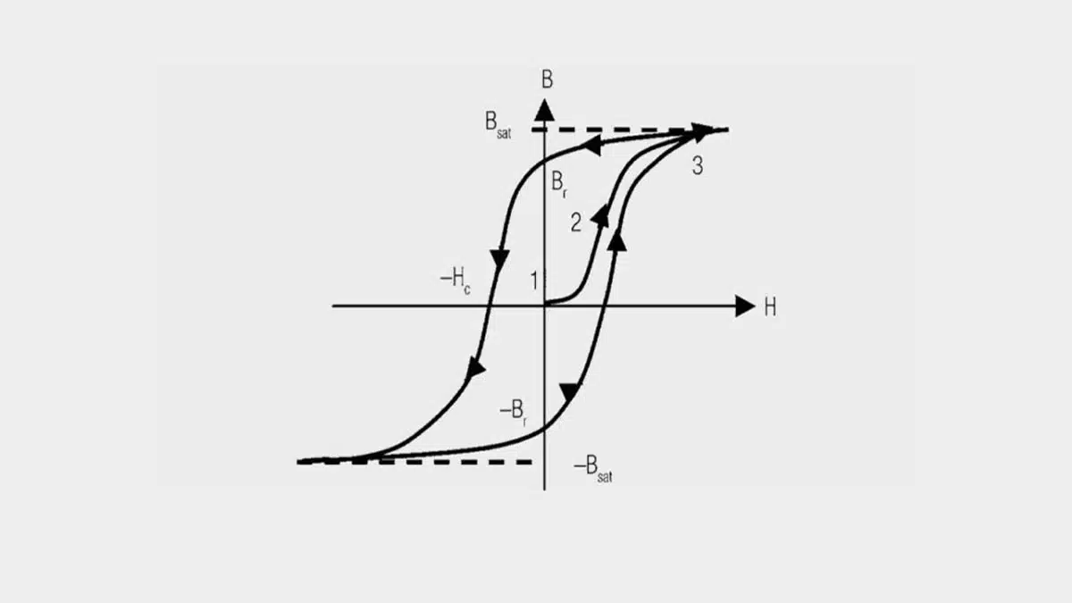
The B–H characteristic describes the material’s magnetic response and depends on its previous excitation as well as the present field. Figure 1 introduces the relationship; practical design also requires the relevant hysteresis loops, permeability curves and temperature-dependent magnetization data. [1]
In a suitable operating region, an increase in H produces a substantial increase in B. As the material approaches saturation, the incremental increase in B becomes much smaller and incremental inductance falls. In a switched-mode converter, this can produce rapidly increasing current, excessive ripple, semiconductor stress and heating.
When the field is reduced and reversed, B does not retrace the original magnetization path. The area enclosed by a complete B–H loop represents energy dissipated per unit volume per cycle. A measured dynamic loop includes the loss mechanisms active under its measurement conditions; it should not automatically be interpreted as static hysteresis loss alone. [1, 6]
- Saturation flux density Bs: a specified high-field flux-density value used to characterize saturation behaviour at a stated temperature and test condition. It is not, by itself, a recommended operating flux density.
- Remanent flux density Br: flux density remaining at zero applied field after a specified magnetization history.
- Coercive field strength Hc: the reverse field needed to bring B to zero on the specified hysteresis loop.
- Initial permeability µi: low-excitation permeability near the demagnetized state, measured under defined conditions.
- Incremental permeability: the permeability associated with a finite AC excursion around a specified operating point. In the small-excursion limit, differential or reversible permeability describes the local response.
For storage inductors, assess the combined DC operating point and AC excursion over the full temperature, tolerance and transient envelope. For ferrite beads and other lossy EMI components, a resistive magnetic contribution may instead be intentional, provided that current capability, self-heating and impedance remain suitable.
Magnetic Core Materials and Their Application Windows
Material selection begins with the component’s function: power transfer, energy storage, current sensing, common-mode filtering or broadband suppression. Table 1 summarizes the principal families; the exact grade, geometry and operating point determine the final result. [1–4]
| Material family | Main strengths | Typical limitations | Common applications |
|---|---|---|---|
| Electrical steel laminations | High saturation capability and established low-frequency manufacturing | Conductivity requires laminated construction; loss limits high-frequency use | Mains transformers, line reactors and rotating machines |
| Iron powder cores | Distributed gap and useful DC-bias capability | Loss, temperature behaviour and ageing characteristics depend on grade and insulation system | Output chokes, PFC inductors and selected RF or power inductors |
| Alloy powder cores | Different compromises among loss, bias capability and temperature stability | No universal ranking; grade-specific curves and cost must be compared | High-current storage inductors, PFC and industrial power magnetics |
| MnZn ferrites | High resistivity and useful permeability for power magnetics | Saturation capability and loss change with temperature, excitation and bias | SMPS transformers, flyback magnetics and gapped inductors |
| NiZn ferrites | High resistivity and useful higher-frequency impedance behaviour | Generally lower permeability than MnZn; exact response is grade-dependent | Beads, cable suppressors, RF and EMI filtering |
| Amorphous ribbon cores | Useful combinations of permeability, saturation capability and loss | Alloy composition, mechanical stress, cutting and transverse fields matter | Distribution transformers, current sensing and specialized magnetics |
| Nanocrystalline ribbon cores | High permeability with useful saturation capability in suitable grades | Gap fringing, leakage fields and assembly stress can be critical | Common-mode chokes, current transformers and selected power transformers |
Electrical steel and laminated cores
Electrical steel, commonly alloyed with silicon, remains important where frequency is low and high saturation capability is useful. Laminations interrupt eddy-current paths; their thickness, coating, joints, stacking and assembly stress influence finished-core loss.
Grain-oriented grades have a preferred magnetic direction and are commonly used in transformer flux paths aligned with that direction. Non-oriented grades are useful where flux direction varies, including rotating machines. Selection must account for the actual flux path rather than treating the two categories as interchangeable.
Conventional electrical steel is generally not the first choice for high-frequency SMPS magnetics. Thin-gauge materials can extend its useful range, but their suitability must be demonstrated with grade-specific loss data and a compatible construction.
Powder cores and distributed gaps
Powder cores contain electrically insulated magnetic particles. The non-magnetic regions between particles create a distributed magnetic gap. Manufacturing and insulation systems vary; an organic binder matrix is not a universal feature of powder cores. [2]
Iron powder is one member of the family. Alloy powders include iron-silicon-aluminium or sendust-type materials, molypermalloy powder or MPP, nickel-iron materials and iron-silicon materials. These represent different compromises among permeability, DC-bias capability, core loss, temperature behaviour and cost.
The distributed-gap structure commonly gives a progressive reduction of permeability and inductance with increasing DC magnetizing force. This can be useful in buck, boost and PFC inductors, output chokes and selected flyback designs. Nevertheless, soft saturation is not unlimited current capability: inductance reduction can increase ripple, peak current and thermal stress.
Compare the inductance remaining at operating current, not only zero-bias inductance. Evaluate loss using the actual grade, waveform, flux excursion and temperature. Where a material uses an insulation or binder system susceptible to thermal ageing, include the manufacturer’s long-term temperature guidance; do not generalize that behaviour to every powder material. [2]
Ferrites: MnZn and NiZn
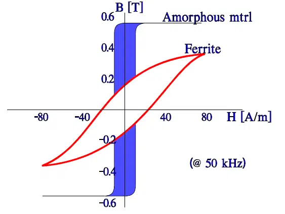
Ferrites are ceramic magnetic materials based on iron oxide combined with other metal oxides, pressed and sintered into the required geometry. Their high electrical resistivity limits classical eddy-current loss, making suitable grades useful for high-frequency power conversion and EMI suppression. Figure 2 retains the ferrite illustration from the companion article. [1]

MnZn ferrites are widely used in power transformers, resonant magnetics and inductors. Their permeability, loss and saturation margin must be checked across excitation, frequency, temperature and bias. In particular, saturation flux density decreases with increasing temperature, so room-temperature magnetization data alone are insufficient. [1]
NiZn ferrites generally have higher resistivity and lower permeability than MnZn grades. They are commonly used in beads, cable suppressors and RF or EMI components where the frequency-dependent impedance is important. Material family does not establish a universal frequency boundary.
Use the exact grade’s permeability, impedance and loss data. Small-signal EMI characteristics must not be substituted for large-signal power-loss curves, and a low loss at one frequency or temperature does not imply low loss throughout the operating envelope.
Amorphous and nanocrystalline ribbon cores
Amorphous alloys lack long-range crystalline order. Nanocrystalline alloys contain very small crystalline regions within a remaining amorphous structure, with their properties controlled through composition and processing. Both families are commonly supplied as thin ribbon and assembled into toroidal, oval or cut-core forms. [3]
Thin ribbon and interlaminar insulation restrict eddy-current paths when flux follows the intended magnetic direction. Iron-based amorphous alloys can reduce distribution-transformer no-load loss compared with conventional grain-oriented steel. Other amorphous compositions serve different sensing or magnetic functions; high saturation capability must not be assumed for every amorphous alloy. [3, 4]
Nanocrystalline cores are established options for current transformers, common-mode chokes and selected power-transformer designs. High permeability can reduce magnetizing current, but a grade optimized for attenuation or sensing is not automatically suitable for power transfer or DC-biased energy storage. Compare the required hysteresis characteristic, loss data, bias capability and mechanical construction. [3]
Discrete gaps, leakage fields and cutting require particular care in ribbon cores. Flux perpendicular to the ribbon plane can drive large in-plane eddy-current loops, while poor cutting can introduce interlaminar electrical connections. These effects are discussed in more detail under Core-Loss Effects Often Missed. [7, 8]
Core Shapes, Gaps and Fringing Fields
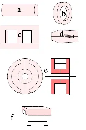
Geometry affects magnetic path length, effective cross-section, winding space, leakage fields, cooling and manufacturability. Common forms include rods, toroids, E-cores, U-cores, pot cores, multi-aperture cores and low-profile planar arrangements. Figures 4–6 illustrate the original core-shape examples.
Toroidal cores
Toroids provide a closed magnetic path and can achieve low external fields when winding distribution and assembly are suitable. They are available in ferrite, powder and ribbon materials, so the shape alone does not identify composition, gap structure or intended application. [2, 3]
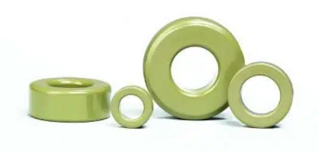
A closed path does not eliminate winding leakage or parasitic capacitance. An ungapped high-permeability toroid can also be unsuitable for substantial uncompensated DC excitation. Consider winding access, insulation coverage, conductor bend radius, terminations and production method together with magnetic performance.
E-shaped, U-shaped and related split cores
Split cores can be assembled around prewound bobbins, foil structures or PCB windings. Their useful properties depend on cross-section, window dimensions, mean turn length, mating surfaces and gap arrangement. Accessible winding windows can simplify construction, but the shape itself does not guarantee lower magnetic or winding loss.
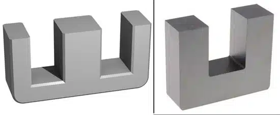
Reducing height or changing the window proportions can alter winding length, leakage, capacitance and cooling. Evaluate these consequences at assembly level rather than assuming that a geometrical change inherently improves flux distribution.
Discrete and distributed gaps
A discrete gap reduces a core assembly’s effective permeability and allows a greater magnetizing current before reaching a given flux density. Much of the magnetic energy in a gap-dominated inductor is stored in the gap field. The gap does not increase the core material’s intrinsic saturation flux density. [1]
If the total effective gap length lg, in metres, dominates magnetic reluctance, Eq. (3) approximates inductance L, in henries. Here µ0 is the permeability of free space, in henries per metre; N and Ae retain their earlier definitions.
Equation (3) neglects finite core reluctance and detailed fringing. It is not a complete model for distributed-gap powder materials or geometries with nonuniform flux. Use the manufacturer’s assembly data or a suitable magnetic-circuit or field model for final calculations.
Fringing fields can increase AC loss in nearby turns and heat conductive clips, shields or PCB copper. In ribbon cores they can also introduce transverse flux and additional core loss. Gap location, conductor spacing and the distribution of multiple gaps must therefore be considered together.
Permeability and Operating Point
Permeability describes the relationship between magnetic excitation and response, but different definitions answer different design questions. Initial material permeability, amplitude permeability, incremental permeability and effective assembly permeability must not be used interchangeably. [1]
For a specified point on a magnetization branch, the secant relative permeability µr can be written as Eq. (4). This ratio is not a universal definition of the local slope of a hysteretic B–H curve and is not meaningful at H = 0.
In an approximately linear region with an appropriate permeability value, the same relationship is written as Eq. (5).
The relevant permeability can change with field strength, AC excursion, frequency, DC operating point, temperature, mechanical stress and material processing. The effective permeability of the assembly additionally incorporates its magnetic path and gap structure.
High permeability can increase inductance with fewer turns, but it does not automatically provide low loss or useful DC-bias capability. Check the inductance available at the required excitation and operating current. For component-level interpretation, see Inductor Saturation Current Explained.
Inductance factor and turns count
Manufacturers commonly specify the inductance factor AL, expressed as inductance per turn squared. Equation (6) relates it to L and N for the specified assembly and measurement conditions. [1]
Check AL tolerance, test frequency, excitation amplitude, temperature and assembly conditions. Small-signal AL does not establish inductance under large AC excitation or DC bias. Likewise, matching nominal AL does not prove equivalent loss, saturation, insulation or thermal performance.
Complex Permeability and EMI Behaviour
For small-signal AC analysis, complex permeability separates the magnetic storage and loss contributions. This is useful in RF and EMI selection, but it does not replace large-signal characterization of a power inductor or transformer. [1]
Using the time convention in which the complex exponential varies as exp(jωt), Eq. (7) defines complex relative permeability µ*. The dimensionless real component µ′ describes the inductive contribution, the dimensionless imaginary component µ″ describes magnetic loss, and j is the imaginary unit.
A ferrite component can therefore be predominantly inductive in one frequency range and predominantly resistive in another. In a suppression bead, the resistive contribution can help damp resonances and dissipate interference energy. The result still depends on source and load impedances, parasitic capacitance, bias and self-heating.
For this magnetic contribution, the loss tangent tan δµ is given by Eq. (8). It is not the complete loss tangent of a winding that also has conductor and other losses. [1]
Use measured impedance, resistance and reactance curves for the actual component over the interference range. For common-mode chokes, include winding capacitance and the relevant excitation mode rather than inferring broadband attenuation from a single permeability value.
Winding Construction and Its Influence on Losses
Conductor type and winding arrangement affect resistance, AC loss, leakage inductance, capacitance, thermal paths and insulation. Skin effect redistributes current within a conductor; proximity fields from adjacent conductors and gaps create additional current crowding. Choose the winding against the actual current spectrum and field distribution, not switching frequency alone. [1, 5]
Solid round wire
Solid round magnet wire is a practical and often economical option. Diameter, conductor length and temperature determine DC resistance, while skin and proximity effects influence AC resistance. Increasing diameter can reduce DC resistance without proportionally reducing high-frequency loss.
Parallel conductors can provide useful construction flexibility, but current sharing depends on placement and termination. Ordinary stranded wire is not automatically equivalent to a purpose-designed high-frequency litz construction.
Litz wire
Litz wire uses multiple individually insulated fine strands in a twisted or bunched construction. Suitable strand diameter and bundle construction reduce high-frequency current crowding. Figure 7 retains the original litz illustration. [5]
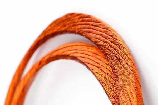
Compare strand diameter, strand count, bundle dimensions, lay construction, outer insulation, thermal class and termination method. Fine strands and insulation occupy winding space, while twisting adds conductor length. Termination quality is important because the intended strands must be connected reliably without compromising the insulation system.
Litz wire can reduce both skin- and proximity-effect losses when appropriately selected, but it is not a universal cure for strong gap-fringing exposure. Verify the actual winding arrangement and compare total loss, production complexity and cost against solid-wire or foil alternatives. [5]
Planar windings, foil, stampings and rectangular wire
Planar is a winding architecture rather than a single conductor material. PCB tracks, foil and stamped conductors can support controlled low-profile geometries, while rectangular wire can improve winding-window utilization. Broad conductors can also provide useful heat-spreading paths, but these benefits depend on the finished construction.
None of these options inherently eliminates proximity loss. Conductor thickness, orientation to the field, layer count, winding overlap, parallel paths and gap position all matter. Thick foil or copper near a discrete gap can develop localized eddy-current loss.
Interleaving can reduce leakage inductance while increasing interwinding capacitance. Evaluate this trade-off against switching behaviour, common-mode noise and insulation requirements. A high copper fill factor is useful only if the assembly also meets its AC-loss, temperature and dielectric limits.
Where Core and Winding Losses Come From
Core loss is dissipation within the magnetic material. Winding loss, termination loss and eddy-current heating in nearby structures are separate contributions, although all affect the component’s temperature. Table 2 distinguishes the main mechanisms and prevents misleading comparisons of core loss alone. [1, 6–8]
| Loss contribution | Physical origin | Important variables |
|---|---|---|
| Static hysteresis-related loss | Irreversible magnetic processes represented by a quasi-static loop | Material, excursion, temperature, bias and magnetic history |
| Classical eddy-current loss | Induced circulating currents in conductive magnetic material | Resistivity, thickness, geometry, frequency and field direction |
| Residual or excess dynamic loss | Additional dynamic magnetic processes not captured by the selected static and classical terms | Material, waveform, transition rates and characterization method |
| Winding DC loss | Resistive loss associated with the DC current component | DC resistance at operating temperature and DC current |
| Winding AC loss | Resistive loss from ripple or AC current, including skin, proximity and fringing effects | Current spectrum, conductor geometry, winding placement and gap fields |
| Termination and adjacent-conductor loss | Contact resistance and induced currents in clips, shields, lead frames or PCB copper | Connections, conductivity, loop geometry and field exposure |
Do not add an independently estimated hysteresis or eddy-current term to a measured total core-loss curve unless the modelling method explicitly separates those contributions. Otherwise, the same loss can be counted twice.
For a voltage-driven transformer, adding turns can reduce flux excursion and core loss while increasing winding length and resistance. For a storage inductor, a turns change usually requires coordinated changes to the gap and inductance specification. In either case, optimize total loss and temperature distribution; there is no universal requirement for core and winding losses to be equal.
Core-Loss Estimation Methods
Empirical loss curves and models are useful only within their defined conditions. Frequency, waveform, temperature, bias, flux convention and core geometry must be sufficiently comparable to the application. Start with appropriate manufacturer measurements and use modelling to interpolate or extend them only within justified limits. [1, 6]
Steinmetz equation and flux convention
The original Steinmetz power law is normally fitted to sinusoidal excitation. Equation (9) writes it using peak-to-peak flux excursion ΔB, in teslas, excitation frequency f, in hertz, and volumetric loss density Pv, in watts per cubic metre. The fitted exponents α and β are dimensionless; coefficient kΔ depends on the chosen units, temperature, material and fitting range. [6]
Many publications instead use the sinusoidal peak amplitude B̂ with a coefficient k. For symmetric sinusoidal excitation, ΔB = 2B̂, so the equivalent coefficient in Eq. (9) is kΔ = k/2β. Do not use a peak-amplitude coefficient with peak-to-peak flux without this conversion. Also check whether the manufacturer reports loss per volume, per mass or per core set.
The coefficients are local empirical fits, not universal material constants. A fit obtained in one frequency, temperature or flux range can become inaccurate outside it. A sinusoidal fit alone does not establish the loss under asymmetric triangular, trapezoidal, burst or strongly biased excitation.
Waveform-aware methods
The improved generalized Steinmetz equation, or iGSE, evaluates the time variation of flux through dB/dt together with flux excursion. It is therefore more informative than applying a sinusoidal frequency-only fit to an arbitrary converter waveform. Correct treatment of minor loops and coefficient normalization remains necessary. [6]
Waveform-aware modelling is relevant to flyback, forward, buck, boost, PFC, phase-shifted and resonant converters. However, a basic iGSE implementation does not automatically include DC-bias dependence, magnetic relaxation, spatially nonuniform flux or transverse-field loss.
- Prefer measured loss curves or maps near the intended waveform, temperature, frequency, flux excursion and bias.
- Use fitted coefficients only within their characterized range and with matching units and flux definitions.
- Apply a suitable waveform-aware method when excitation is non-sinusoidal, including the treatment of significant minor loops.
- Assess bias, relaxation and field-distribution effects separately when they are not represented by the chosen data or model.
- Validate total loss and hot spots on representative assemblies rather than relying only on a material sample or software estimate.
Core-Loss Effects Often Missed
Several mechanisms can cause a finished component to dissipate more energy than predicted by a simple one-dimensional loss calculation. The following effects are particularly important in biased inductors, converters with dwell intervals and tape-wound magnetic assemblies. [6–8]
DC premagnetization
A DC magnetizing component shifts the operating point and changes the minor loops traced by the AC excitation. The same AC flux excursion can therefore produce different loss at different DC bias, even before saturation becomes a problem.
This matters in buck and boost inductors, PFC chokes, sensing components and transformers with asymmetric excitation. A low-frequency current envelope can also bias the high-frequency minor loops differently over the line cycle.
The magnitude and direction of the loss change depend on material and operating point. Measurements reported in the cited work show significant increases for selected ferrites and other materials, while some tested powder cores showed a smaller response. These observations must not be generalized to every grade. Use bias-dependent loss data or measurements representative of the intended excitation. [7, 8]
Relaxation after voltage transitions
A nearly zero induced winding voltage corresponds to a nearly constant-flux interval. A nonzero constant voltage plateau does not: it produces an approximately linear flux ramp. Constant-flux dwell intervals can occur in dual-active-bridge and phase-shifted converters, discontinuous operation and other modulation schemes.
A basic iGSE calculation assigns no instantaneous loss contribution where dB/dt is zero. Experiments nevertheless show additional cycle loss associated with relaxation after rapid changes in excitation. The magnetic state continues to evolve towards equilibrium, modifying the dynamic B–H loop. [6]
The improved-improved generalized Steinmetz equation, often written i²GSE, adds empirically characterized relaxation terms. It can improve estimates for the tested waveform classes, but requires additional material parameters and has its own validity limits. It is not a universal substitute for application measurements.
Distinguish energy per cycle from average power. Extending a dwell can increase dissipated energy per cycle while also increasing the period, so average power need not increase. The cited measurements demonstrate this distinction; relaxation loss does not grow indefinitely with dwell time. [6]
Orthogonal flux and cutting effects in tape-wound cores
Ribbon cores are designed so that the main flux follows the intended path within the ribbon plane. Thin insulated layers suppress eddy-current loops associated with that flux direction. A field component perpendicular to the ribbon plane can instead drive extensive in-plane current loops. [7, 8]
Gap fringing and transformer leakage fields can generate this perpendicular component. Consequently, a tape-wound transformer’s core loss can increase with load-related leakage excitation even when its main voltage-driven flux excursion remains similar.
Cutting and finishing can also introduce electrical connections between layers. This interlaminar short-circuit mechanism is separate from transverse-flux loss and requires control of manufacturing and edge treatment.
For a proposed ribbon-core design, assess gap size and distribution, winding placement, leakage fields, cutting quality and local temperatures. Consider lower-permeability grades, distributed-gap arrangements or alternative materials where suitable, but do not remove a required energy-storage gap without redesigning the magnetic circuit. [3, 7, 8]
Mechanical and thermal stress
Clamping, winding tension, encapsulation and differential thermal expansion can alter magnetic properties. Ferrites are brittle ceramics, while high-permeability ribbon assemblies can also be sensitive to mechanical loading. The effects depend on the material and construction. [1, 3]
Validate the finished assembly after relevant mounting, potting and environmental processes. A loose-core measurement does not establish the permeability, accuracy or loss of the final component.
Application Fit
Table 3 provides starting points, not prescriptions. Final selection depends on exact grade, waveform, current, temperature, gap, winding arrangement and qualification requirements. The same material family can support different functions only with an appropriate design. [1–4]
| Application | Starting material families | Primary selection checks |
|---|---|---|
| Mains transformer or line reactor | Electrical steel; suitable amorphous materials for selected designs | Flux waveform, no-load and load losses, acoustic behaviour, temperature and insulation |
| PFC inductor or boost choke | Powder materials or gapped ferrite | Bias-dependent inductance, peak current, line-cycle operating points and fringing loss |
| Flyback coupled inductor | Gapped MnZn ferrite; selected powder designs | Stored energy, inductance under load, flux excursion, leakage and insulation |
| Forward or bridge transformer | Suitable power ferrite; selected ribbon designs | Volt-second balance, reset, core loss, magnetizing current and isolation |
| LLC transformer or resonant inductor | Low-loss power ferrite; specialized alternatives where justified | Full frequency and load range, magnetizing current, intended leakage and temperature |
| Buck or multiphase output inductor | Powder material or gapped ferrite | Inductance roll-off, ripple, peak current, AC winding loss and thermal coupling |
| Current-sense transformer | Ferrite, nanocrystalline or suitable amorphous material | Magnetizing error, burden, bandwidth, reset, saturation and insulation |
| Common-mode choke | Ferrite or nanocrystalline material | Common-mode impedance, unbalanced excitation, winding current, capacitance and temperature |
| Ferrite bead or cable suppressor | NiZn or other application-specific ferrite | Impedance across the interference spectrum, bias, current rating and self-heating |
A flyback magnetic component intentionally stores energy and is therefore assessed as a coupled energy-storage inductor, even though it is commonly called a transformer. A forward or bridge transformer requires a different magnetizing and reset assessment.
In an ideal common-mode choke, normal differential load-current ampere-turns cancel in the core. The conductor current rating remains important for heating, while residual imbalance and common-mode excitation determine the associated core magnetization. A single-winding DC-bias rating must not be substituted for this modal assessment.
Customization and Developing Material Options
Custom designs and evolving material grades are useful when they improve a quantified requirement such as loss, bias capability, component height, cooling or repeatability. Neither a new material label nor a more complex geometry establishes a better component without application-level evidence.
Catalog versus custom geometry
Begin with available core, bobbin and conductor systems. Customization may be justified by winding space, a mechanical interface, thermal access, an insulation barrier or a required gap arrangement. Specify the expected benefit and the production tolerances that preserve it.
Conventional cores are already three-dimensional objects. For unconventional three-dimensional magnetic paths, the meaningful questions concern flux concentration, field direction, winding access and manufacturability, not a simple two-dimensional versus three-dimensional label.
Hybrid cores and coordinated winding design
A hybrid arrangement can combine materials or magnetic sections for a defined circuit function. Each section must still be assessed for local flux, reluctance, saturation, loss and temperature. Combining attractive material properties does not automatically combine their advantages in the finished magnetic circuit.
Core and winding customization should proceed together. Changing core dimensions or gaps alters conductor length, fringing exposure, leakage, capacitance and insulation space. Controlled winding placement can improve repeatability, but its electrical and thermal benefit must be measured.
Material improvements that affect selection
Commercial powder and ribbon portfolios offer different loss, permeability and bias compromises. The useful engineering development is a wider set of characterized operating windows, not a universal replacement for an established family. Compare the latest data for the exact grade and assembly while retaining the same application-level validation process. [2, 3]
Design and Selection Checklist
A release-ready magnetic specification connects the circuit requirements to measurable component limits. The checklist below extends material selection to winding construction, procurement, safety and validation.
Define the operating envelope
- State the function and topology, voltage waveform, switching range, modulation, duty cycle and any line-frequency or burst envelope.
- Define DC, RMS, ripple and peak current, including start-up, imbalance and relevant overload conditions.
- Specify ambient and cooling conditions, component temperature limits, mounting, dimensions and nearby conductive structures.
- Calculate flux excursion using Eqs. (1) and (2), then include the initial operating point, reset and worst-case tolerances when checking peak flux.
Compare datasheet and construction parameters
- Record the exact material grade, effective and minimum cross-sections where specified, magnetic path length, effective volume, winding window and gap arrangement.
- Compare AL, tolerance, test frequency, amplitude, temperature and inductance under the required bias and excitation.
- Compare core-loss data using consistent frequency, waveform, flux convention, temperature, bias and normalization units.
- Assess DC and AC winding loss, conductor and termination temperature, leakage inductance and relevant capacitances.
- Check fringing exposure, local hot spots, core coatings, clamps, encapsulation and assembly stress.
Control catalog selection and purchasing
A catalog component is suitable only when its specified conditions cover the application. For a custom assembly, define the required electrical, thermal, mechanical and dielectric performance rather than prescribing a material name alone.
Document material grade, gap or AL range, turns and winding construction, insulation materials, critical dimensions, acceptance tests, traceability and supplier change control. Evaluate substitutions against these conditions: matching nominal inductance is not sufficient, and cores or accessories from different manufacturers may require compatibility testing. [1]
Qualify insulation, safety and reliability
Core material does not establish electrical isolation or equipment safety. Define working voltage, insulation function, creepage, clearance, winding-to-core separation, dielectric test requirements and thermal limits according to the intended equipment. Check the approval scope of the exact wire, insulation system and component construction. [5]
Validate representative assemblies over worst-case input, load, frequency, ambient temperature and cooling conditions. Measure waveforms, inductance under relevant bias, losses, core and winding hot spots, and EMI performance. Include mounting and encapsulation effects and the environmental or mechanical qualification needed by the application.
Allow margin for material spread, gap tolerance, temperature, DC offset and start-up behaviour. For topology-specific calculations, see Buck Converter Design and Calculation and Flyback Converter Design and Calculation.
Conclusion
Magnetic-core selection is a coordinated choice of material, geometry, gap, winding and insulation construction. Ferrites, powder materials, electrical steels, amorphous alloys and nanocrystalline alloys each serve useful operating windows rather than a universal performance hierarchy.
Start with the electrical function and actual waveform, calculate flux excursion, check inductance and saturation at temperature and bias, and evaluate core and winding loss separately. Include fringing, leakage, relaxation and mechanical effects where they matter, then validate the finished assembly and release a controlled specification.
FAQ
These answers summarize the main material, loss and construction decisions discussed in the article.
A magnetic core increases flux linkage and inductance for a suitable winding and magnetizing current, enabling compact inductors, transformers and filtering components. Common families include electrical steel, iron and alloy powders, ferrites, amorphous alloys and nanocrystalline alloys. The core also introduces saturation and loss limits, so selection must begin with the component’s function and operating conditions.
Power ferrites are common starting points for SMPS transformers and gapped inductors. Powder cores offer distributed gaps useful in DC-biased energy-storage applications. Amorphous and nanocrystalline ribbon cores serve sensing, filtering and selected transformer designs. Compare exact grades using loss, bias, temperature and construction data; no family is best across every waveform, current level or frequency range.
Higher effective permeability can increase inductance for a given winding and geometry. The inductance factor relates inductance to turns squared under defined measurement conditions. Neither value is necessarily constant with bias, excitation or temperature. Check the required operating inductance and distinguish initial material permeability from the effective permeability of the assembled core and its gaps.
A gap reduces effective permeability and allows greater magnetizing current before reaching a given flux density, but it does not raise the material’s intrinsic saturation flux density. Fringing fields can increase AC loss in nearby conductors and produce transverse-flux loss in ribbon cores. Gap size, distribution and winding placement therefore require coordinated magnetic and thermal assessment.
Magnetic loss includes hysteresis-related, classical eddy-current and residual dynamic contributions. Winding DC and AC losses, termination resistance and induced heating in nearby conductors are separate. A measured total core-loss curve may already include several magnetic mechanisms, so avoid double counting. Optimize total dissipation and hot spots rather than core loss or DC resistance alone.
Steinmetz coefficients are empirical fits for stated conditions and often originate from sinusoidal measurements. Their flux convention, units, temperature and fitting range must match the calculation. Waveform-aware methods improve treatment of changing flux, but basic implementations do not automatically include DC bias, relaxation, minor-loop details or spatially nonuniform fields. Representative measurements remain necessary.
DC premagnetization changes the operating point and minor loops, so identical AC flux excursion can produce different loss under bias. Relaxation after an excitation transition can add cycle energy beyond a basic waveform estimate. The magnitude is material-dependent. A longer constant-flux dwell can increase energy per cycle without increasing average power because the cycle period can also change.
Litz wire can reduce high-frequency current crowding when its individually insulated strands and bundle construction suit the current spectrum and field distribution. It also adds insulation volume, length and termination requirements. Compare its total loss and manufacturing cost against alternatives in the actual winding. Foil, rectangular and planar conductors offer useful geometries but do not inherently eliminate proximity or fringing losses.
How to Select and Validate a Magnetic Core Assembly
Use this procedure to connect material selection with winding design and prototype validation. It applies to inductors, transformers and filtering components when the function-specific checks are included.
Select a magnetic material, core geometry and winding construction, then validate the finished assembly.
- Define the component function
Identify energy storage, power transfer, sensing or suppression, and state the topology, insulation function, dimensions and thermal constraints.
- Derive the operating waveforms
Determine induced winding voltage, frequency range, switching intervals, DC and ripple currents, peak excitation, start-up conditions and any line-frequency or burst modulation.
- Shortlist materials and geometries
Compare exact material grades and available cores against loss, permeability, bias capability, winding space, gaps, cooling and manufacturing requirements.
- Check flux and operating inductance
Calculate flux excursion from winding volt-seconds and check the absolute operating point, reset and saturation margin. Verify inductance and permeability under the required current, excitation and temperature.
- Estimate magnetic and conductor losses
Use compatible measured data or a suitable waveform model with consistent units and flux definitions. Include relevant bias, relaxation, fringing, leakage and transverse-field effects without double counting losses.
- Select winding and insulation construction
Compare round wire, litz, foil, stampings, rectangular wire or planar arrangements. Check resistance, current sharing, leakage, capacitance, terminations, insulation distances and thermal paths.
- Measure representative assemblies
Validate waveforms, operating inductance, losses, hot spots, EMI and dielectric performance across the operating envelope and relevant mounting or environmental conditions.
- Release a controlled specification
Allow margin for temperature, tolerances and transients. Document material, construction, acceptance limits, test conditions, traceability and supplier change controls before production release.
Further Reading
These articles extend the component fundamentals and application-specific checks introduced here.
- Inductor and Choke, What is it? — Component fundamentals, equivalent circuits and the distinction between storage, filtering and suppression functions.
- Why Power Inductors Use a Ferrite Core With an Air Gap — Additional explanation of energy storage and gapped ferrite construction.
- Inductance, Impedance, Q Factor and DCR Losses — Electrical parameters and frequency-dependent loss in practical inductors.
- Current Sense Transformers: Ferrite vs Nanocrystalline Cores for Accurate Current Measurement — How magnetizing impedance and material choice influence current-transformer performance.
- How Transformers and Solenoids Work — Coupled-winding principles, transformer calculations, parasitics and insulation considerations.
References
The following manufacturer documents, research publications and educational presentation support the material properties and loss mechanisms discussed above. Undated online documents are identified as such.
- TDK Electronics, Ferrites and Accessories: General — Definitions, TDK Electronics, October 2022.
- Magnetics, Powder Cores, Magnetics, undated online technical overview.
- VACUUMSCHMELZE, Amorphous and Nanocrystalline Cores, VACUUMSCHMELZE, undated online technical overview.
- Metglas, Distribution Transformer Electrical Steel, Metglas, undated online technical overview.
- ELEKTRISOLA, Litz Wire: Product Program and Technical Data, ELEKTRISOLA, revision March 2025.
- J. Mühlethaler, J. Biela, J. W. Kolar and A. Ecklebe, Improved Core-Loss Calculation for Magnetic Components Employed in Power Electronic Systems, IEEE Transactions on Power Electronics, volume 27, number 2, February 2012.
- J. Mühlethaler and J. W. Kolar, Core Loss Modeling of Inductive Components: Effects with Considerable Impact on Core Losses, ETH Zurich Power Electronic Systems Laboratory, presentation, 2012.
- J. Mühlethaler, Effects with Considerable Impact on Core Losses, Frenetic Webinar Series, 17 April 2024.