Passive Components Blog
No Result
View All Result
  • Home
  • NewsFilter
    • All
    • Aerospace & Defence
    • Antenna
    • Applications
    • Automotive
    • Capacitors
    • Circuit Protection Devices
    • electro-mechanical news
    • Filters
    • Fuses
    • Inductors
    • Industrial
    • Integrated Passives
    • inter-connect news
    • Market & Supply Chain
    • Market Insights
    • Medical
    • Modelling and Simulation
    • New Materials & Supply
    • New Technologies
    • Non-linear Passives
    • Oscillators
    • Passive Sensors News
    • Resistors
    • RF & Microwave
    • Telecommunication
    • Weekly Digest

    Inductor Resonances and its Impact to EMI

    Developing Low Inductance Film Capacitor using Bode 100 Analyzer

    Highly Reliable Flex Rigid PCBs, Würth Elektronik Webinar

    Würth Elektronik Releases High Performance TLVR Coupled Inductors

    YAGEO Extends Rectangular Aluminum Electrolytic Capacitor Family

    Dr. Tomas Zednicek Vision for Europe 2025 Passive Electronics Market

    Littelfuse Releases Industry-First SMD Fuse with 1500A Interrupting Rating at 277V

    TDK Unveils Industry Highest Rated Current Multilayer Chip Beads

    Vishay Releases Automotive SMD Thick Film Power Resistor for Enhanced Protection Against Short Transient Pulses

    Trending Tags

    • Ripple Current
    • RF
    • Leakage Current
    • Tantalum vs Ceramic
    • Snubber
    • Low ESR
    • Feedthrough
    • Derating
    • Dielectric Constant
    • New Products
    • Market Reports
  • VideoFilter
    • All
    • Antenna videos
    • Capacitor videos
    • Circuit Protection Video
    • Filter videos
    • Fuse videos
    • Inductor videos
    • Inter-Connect Video
    • Non-linear passives videos
    • Oscillator videos
    • Passive sensors videos
    • Resistor videos

    Inductor Resonances and its Impact to EMI

    Highly Reliable Flex Rigid PCBs, Würth Elektronik Webinar

    Causes of Oscillations in Flyback Converters

    How to design a 60W Flyback Transformer

    Modeling and Simulation of Leakage Inductance

    Power Inductor Considerations for AI High Power Computing – Vishay Video

    Coupled Inductors in Multiphase Boost Converters

    VPG Demonstrates Precision Resistor in Cryogenic Conditions

    Comparison Testing of Chip Resistor Technologies Under High Vibration

    Trending Tags

    • Capacitors explained
    • Inductors explained
    • Resistors explained
    • Filters explained
    • Application Video Guidelines
    • EMC
    • New Products
    • Ripple Current
    • Simulation
    • Tantalum vs Ceramic
  • Knowledge Blog
  • Suppliers
    • Who is Who
  • Events
No Result
View All Result
Passive Components Blog
No Result
View All Result

USB PD 3.0 Flyback Transformer Optimisation

30.1.2023
Reading Time: 8 mins read
A A

In this blog article Sotiris Zorbas, MSc, Frenetic power electronics engineer, suggests USB PD 3.0 compatible flyback transformer optimisation, and how to select the best fit core type using the Core Optimizer™️ tool in Frenetic Magnetics design software.

Let’s consider the drawbacks of flyback transformer designs as in example of Frenetic EQ25 design (Figure 1.):

RelatedPosts

How to design a 60W Flyback Transformer

How to Design LLC Transformer

Leakage Inductance Model; Frenetic Webinar Recording

1. Flying leads at the secondary side

For those of you that haven’t heard of this before, that’s just one design choice when we have a winding ending. There are two options:

  • Terminate the wire to the coil former pin.
  • Leave some cm of extra wire to solder it directly to the PCB. Although this might seem like a simple design choice, the truth is that doing so creates extra manual labour when it comes to the assembly of the PCB board the flyback transformer will be mounted on to. Human intervention is costly!
Figure 1. Frenetic EQ25 USB PD 3.0 Flyback Transformer (conventional “old” design)

Question: Why do we need flying leads in the first place?

Answer: There are a couple of reasons to go for flying leads. In low power transformers/inductors, the reason is high voltages. For a transformer to pass safety standards and be safe to use, many times the distances of the pins between themselves, or with respect to the core, are not enough. For high power applications, the current levels resulting in the use of big wire dimensions create mounting issues. Up to certain wire dimensions things are simple, and the wires can be soldered to the pins. After a point though, that is not an option anymore and flying leads is the decision to go for.

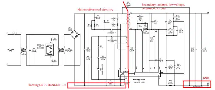
For the flyback design we’re analysing, the problem is high voltages (up to 375VDC in the primary side). Reinforced insulation was selected and, based on IEC61558-1 automotive standard, >6mm of creepage distance is necessary to pass regulation. The EQ25 design shown in Figure 1 can’t pass the standard, if we terminate the secondary winding to the pins, so flying leads are necessary here.

2. Insulating tape for the core (externally)

Just to remind the situation here, the core itself is made of ferrite. We have a primary and a secondary winding. We insulate the primary and/or the secondary to achieve isolation, comply with the standards and pass Hi-pot testing. But the core itself is considered an electrically conductive material, unless coated with insulation, which is not the case with ferrites.

Therefore, we have a conductive material between isolated windings. The transformer will develop some potential if left floating. A solid design choice is to ground the core, either from it clips or by using some copper tape. Conducted EMI is lowered with this design choice.

Question: At which ground should I ground the core?

Answer: We have 2 grounds in USB-PD 3.0 flyback design. The input ground (which is floating – lethal voltages!) and the output ground (safe to touch). Electrically I don’t find a very good reason why grounding the core to one of the grounds is a better option. But I do find that grounding the core at the secondary – safe to touch – ground is a much better option for obvious reasons!

Figure 2. Flyback design – grounds

Without getting into more details, I’ll say that the wire insulation choices at the primary-secondary will either leave the core grounding options open or limit us to a specific choice.

That is the drawback of the EQ25 design. Grounding the core at the secondary side is not allowed, and we are forced to ground the core on the primary side ground. Insulating tape all around the core is needed, being careful to completely cover the ferrite core.

3. Available coil formers.

Unfortunately, the EQ family is not a standard part. EQ cores are planar cores, and that limits the options of coil formers significantly.

Planar cores are called that way because they are designed for planar transformers. That does not exclude them from the classic coil former style approach. The reverse is also applicable. We can design a planar transformer using standard cores. What’s the price of these choices? Availability issues and a limited range of components choices.

The improved design

Assuming the problems of the previous design, I decided to work on a better version, trying to respect most specs of the previous design to be compatible. The design goals of the new transformer are:

  • No flying leads (solve drawback No1)
  • Core can be grounded on the secondary side ground (solve drawback No2)
  • Standard core (solve drawback No3)
  • Maximum power raised at 100W (previous design at 60W)

Let’s focus now on the core selection process. Other aspects of the design will be discussed in the next Newsletters, so stay tuned!

To start the design, I used the Core Optimizer™️ feature of our magnetics design program. This new powerful tool available in Frenetic Online is helping engineers find the appropriate core for a particular application without having to rely on experience and empirical formulas.

Step 1. Decide on the core family/dimensions

As shown in Figure 3, different families of cores were plotted in a volume-primary turns graph. Using height as the deciding factor, I selected the ETD29/16/10 core. To be honest, other similar high options were also available, but they were excluded because of insulation reasons, that have to do with the non-flying lead design choice, made for this design.

Having the ETD29/16/10 core in mind, I moved on to the second graph of the Core Optimizer, that gave me a clear perspective of the core losses under different operating conditions (worst case scenarios).

Figure 3. Core Optimizer™️
Figure 4. Core losses of different materials – same operating conditions

Step 2. Decide on the core loss target

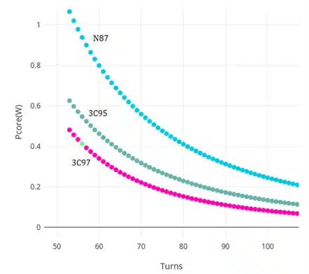
Core loss target set at <0.5W. Three core materials were selected (for ETD29/16/10). Plotting the core losses under the same operating conditions (worst case scenario), we got the following graph shown in Figure 4.

Figure 5. Core losses at different operating conditions

We see a difference of ~0.1W between 50-100 turns for 3C95-3C97. That’s not a lot and both materials could be used. On the other hand, N87 material is not a good option here, having almost x2 power losses. So I picked the 3C97 material.

Step 3. Decide on the number of turns

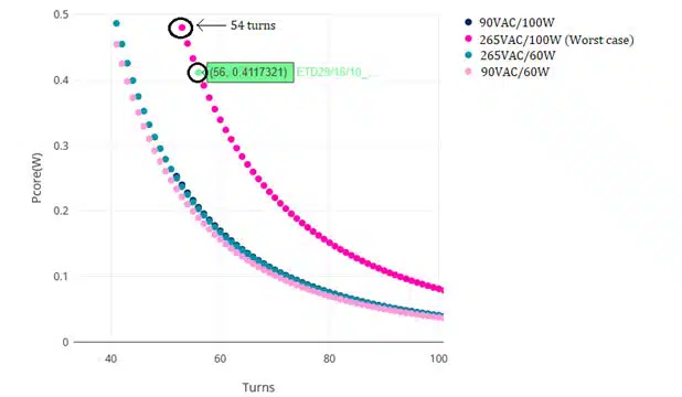
In Figure 5, having selected 3C97 material, the core losses are shown for different operating conditions. The worst-case scenario, as far as the core losses are concerned, is the combination of 265VAC input voltage and output power at 100W. Selecting 54 turns would be ok for losses <0.5W, but in the end I chose 56 turns to make sure the turns ratio (Np/Ns = 7) would result in an integer number of secondary turns.

The New ETD29 Transformer Design

You can have a look now at the new ETD29 transformer design in Figure 6. and online with details here.

The table 1. shows the specs and differences between the old and new design.

Figure 6. New Frenetic ETD29 USB PD 3.0 Flyback Transformer
Table 1. Frenetic ETD29 (new) vs EQ25 (old) USB PD 3.0 Flyback Transformer Specification comparison

References

[1]  Applications Engineering Department, “Reference Design Report for a 65 W Power Supply Using InnoSwitchTM3-EP PowiGaNTM INN3679C-H606”, Power Integrations 

Related

Source: Frenetic

Recent Posts

Inductor Resonances and its Impact to EMI

16.5.2025
4

Würth Elektronik Releases High Performance TLVR Coupled Inductors

15.5.2025
13

Causes of Oscillations in Flyback Converters

15.5.2025
7

TDK Unveils Industry Highest Rated Current Multilayer Chip Beads

14.5.2025
16

How to design a 60W Flyback Transformer

12.5.2025
27

Murata Releases 008004 High-Frequency SMD Chip Inductor

12.5.2025
21

Modeling and Simulation of Leakage Inductance

9.5.2025
23

Power Inductor Considerations for AI High Power Computing – Vishay Video

9.5.2025
28

TAIYO YUDEN Releases Compact SMD Power Inductors for Automotive Application

9.5.2025
17

YAGEO Releases High Current SMD Common Mode Choke With Shape Core Construction

5.5.2025
28

Upcoming Events

May 28
16:00 - 17:00 CEST

Power Over Data Line

View Calendar

Popular Posts

  • Buck Converter Design and Calculation

    0 shares
    Share 0 Tweet 0
  • Boost Converter Design and Calculation

    0 shares
    Share 0 Tweet 0
  • LLC Resonant Converter Design and Calculation

    0 shares
    Share 0 Tweet 0
  • Flyback Converter Design and Calculation

    0 shares
    Share 0 Tweet 0
  • Developing Low Inductance Film Capacitor using Bode 100 Analyzer

    0 shares
    Share 0 Tweet 0
  • Dual Active Bridge (DAB) Topology Explained

    0 shares
    Share 0 Tweet 0
  • What is a Dielectric Constant and DF of Plastic Materials?

    4 shares
    Share 4 Tweet 0
  • What is the Difference Between X8G, X8L and X8R Ceramic Capacitor Dielectrics?

    0 shares
    Share 0 Tweet 0
  • YAGEO Extends Rectangular Aluminum Electrolytic Capacitor Family

    0 shares
    Share 0 Tweet 0
  • SEPIC Converter Design and Calculation

    0 shares
    Share 0 Tweet 0

Newsletter Subscription


Passive Components Blog

© EPCI - Leading Passive Components Educational and Information Site

  • Home
  • Privacy Policy
  • EPCI Membership & Advertisement
  • About

No Result
View All Result
  • Home
  • Knowledge Blog
  • Premium Suppliers

© EPCI - Leading Passive Components Educational and Information Site

This website uses cookies. By continuing to use this website you are giving consent to cookies being used. Visit our Privacy and Cookie Policy.
Go to mobile version