Passive Components Blog
No Result
View All Result
  • Home
  • NewsFilter
    • All
    • Aerospace & Defence
    • Antenna
    • Applications
    • Automotive
    • Capacitors
    • Circuit Protection Devices
    • electro-mechanical news
    • Filters
    • Fuses
    • Inductors
    • Industrial
    • Integrated Passives
    • inter-connect news
    • Market & Supply Chain
    • Market Insights
    • Medical
    • Modelling and Simulation
    • New Materials & Supply
    • New Technologies
    • Non-linear Passives
    • Oscillators
    • Passive Sensors News
    • Resistors
    • RF & Microwave
    • Telecommunication
    • Weekly Digest

    April 2026 Interconnect, Passives and Electromechanical Components Market Insights

    SPICE Simulation of Non-Linear Resistors: Vishay’s Thermistor and PPTC Modelling Ecosystem

    KYOCERA AVX Introduces Traction‑Grade DC Link Film Capacitors

    When More Capacitance Hurts Reliability: The Role of the Metallic Skeleton in Tantalum Anodes

    Why Power Inductors Use a Ferrite Core With an Air Gap

    Wk 16 Electronics Supply Chain Digest

    YAGEO Introduces High‑Current Y2/X1 Film Capacitors for Wide-bandgap Power Systems

    Amphenol Explanded Liquid Cooling Connectors for AI, ESS and EV Systems

    Hirose Introduced BGA connector for PCIe Gen6 for AI and Edge Computing

    Trending Tags

    • Ripple Current
    • RF
    • Leakage Current
    • Tantalum vs Ceramic
    • Snubber
    • Low ESR
    • Feedthrough
    • Derating
    • Dielectric Constant
    • New Products
    • Market Reports
  • VideoFilter
    • All
    • Antenna videos
    • Capacitor videos
    • Circuit Protection Video
    • Filter videos
    • Fuse videos
    • Inductor videos
    • Inter-Connect Video
    • Non-linear passives videos
    • Oscillator videos
    • Passive sensors videos
    • Resistor videos

    Why Power Inductors Use a Ferrite Core With an Air Gap

    Transformer-Based Power-Line Harvester Magnetic Design

    Thermal Modeling of Magnetics

    Standard vs Planar LLC transformers Comparison for Battery Chargers

    How Modern Tools Model Magnetic Components for Power Electronics

    Advanced Loss Modeling for Planar Magnetics in the Frenetic Planar Tool

    2026 Power Magnetics Design Trends: Flyback, DAB and Planar

    Enabling Software‑Defined Vehicle Architectures: Automotive Ethernet and Zonal Smart Power

    Calculating Resistance Value of a Flyback RC Snubber 

    Trending Tags

    • Capacitors explained
    • Inductors explained
    • Resistors explained
    • Filters explained
    • Application Video Guidelines
    • EMC
    • New Products
    • Ripple Current
    • Simulation
    • Tantalum vs Ceramic
  • Knowledge Blog
  • DossiersNew
  • Suppliers
    • Who is Who
  • PCNS
    • PCNS 2025
    • PCNS 2023
    • PCNS 2021
    • PCNS 2019
    • PCNS 2017
  • Events
No Result
View All Result
Passive Components Blog
No Result
View All Result

Waveguides and Transmission Lines Explained

23.6.2022
Reading Time: 4 mins read
A A

This blog article from Knowles Precision Devices explains background information on how waveguides and transmission line filters do what they do.

Two important methods for propagating electromagnetic waves around a circuit are waveguides and transmission lines. At a high level, the main difference between these two methods is the number of conductors involved and the types of electromagnetic modes supported. Let’s explore how these types of electromagnetic modes work and how they are supported, or not supported, by waveguides and transmission lines.

RelatedPosts

Knowles Doubles Capacitance of its Class I Ceramic C0G Capacitors

Knowles Releases High Q Non-Magnetic X7R MLCCs for Medical Imaging

Knowles Unveils High-Performance Safety-Certified MLCC Capacitors

Three Types of Electromagnetic Modes

When we say “modes”, what we are referencing is the different solutions to the electromagnetic field equations for the particular structure we are referring to. These three modes include transverse magnetic (TM), transverse electric (TE), and transverse electro-magnetic (TEM).

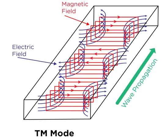
A TM mode solution involves the electric (E) field having components in the z-direction, which is along the direction of propagation, so that the magnetic (H) field is transverse, or at right angles to the z-direction (Figure 1).

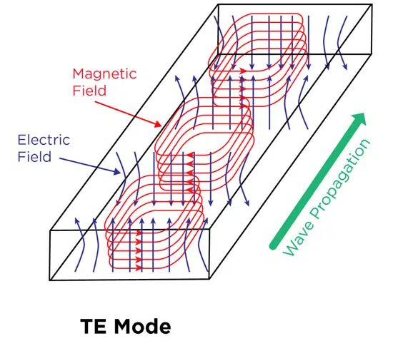
On the other hand, TE mode has E field components at right angles to the z-direction as shown in Figure 2.

Figure 1. The E and H fields for TM mode moving in a rectangular waveguide.
Figure 2. The E and H fields for TE mode moving in a rectangular waveguide.

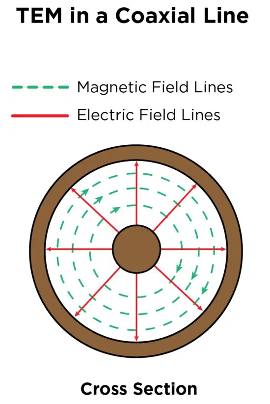
TEM mode has E field and H field components at right angles to the Z direction. Figure 3a shows an example of an electromagnetic wave propagating through space in TEM mode while Figure 3b shows how TEM mode works in a cross-section of a coax cable.

Figure 3a. Example of an electromagnetic wave propagating through space in TEM mode
Figure 3b. TEM mode in a cross-section of a coax cable

The Different Modes Supported by Transmission Lines and Waveguides

When we look at transmission lines and waveguides in terms of the electromagnetic modes supported, we can make clear distinctions between the two. A waveguide is a hollow tube made of a single conducting surface, which means it cannot support TEM mode.

Figure 4. A representation of substrate-integrated waveguide SIW.

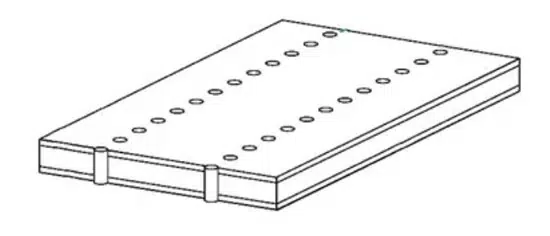
We usually see waveguides designed as a metal tube, but in recent years, the development of substrate-integrated waveguide (SIW) technology is changing this. An SIW is basically a rectangular waveguide in which the single conductor walls are formed by plated surfaces and vias. In this format, the wave uses TE mode to propagate in high dielectric-constant materials. A depiction of an SIW is shown in Figure 4.

Since a transmission line is a two-conductor structure, it can carry electromagnetic waves using TEM mode. A common example of a transmission line, although it is sort of going out of style now, is the coax cable shown in Figure 3b, which carries DOCSIS signals to cable TV boxes. Additional transmission line examples, the modes one would usually see, and their traditional performance characteristics compared to what you would see with a waveguide are all outlined in Table 1.

Table 1. With all other qualities of the application being equal, this Table provides an overview of how waveguides and different transmission line methods compare; source: Knowles Precision Devices

To summarize, the biggest thing to remember when it comes to waveguides versus transmission lines is that a waveguide = one conductor (usually a tube) and a transmission line = more than one conductor, such as the structure seen in a coax cable.

Related

Source: Knowles Precision Devices

Recent Posts

When More Capacitance Hurts Reliability: The Role of the Metallic Skeleton in Tantalum Anodes

20.4.2026
23

Why Power Inductors Use a Ferrite Core With an Air Gap

20.4.2026
15

AI-Assisted Structural Diagnostics and Physics-Based Reliability Interpretation of Tantalum Capacitor Anodes

14.4.2026
33

TDK Releases Ultra‑small EMI Noise Suppression Filters

8.4.2026
24

Equivalent Circuit Constants of Crystal Units Explained

26.3.2026
53

Nanocrystalline Cores for Low‑Loss MHz Chip Inductors

25.3.2026
67

Transformer-Based Power-Line Harvester Magnetic Design

24.3.2026
37

Tantalum Capacitor Anode Manufacturing Quality Management

23.3.2026
72

LLC Transformer: Designing a 2 kW LLC Transformer with Integrated Resonant Inductor

26.3.2026
209

Upcoming Events

Apr 29
10:00 - 11:00 CDT

SEPIC Design Done Right

May 5
16:00 - 17:00 CEST

Understanding and Selecting Capacitors – Fundamentals, Technologies and Latest Trends

May 12
16:00 - 17:00 CEST

Accelerating Power Supply Design with Wurth Elektronik and STMicroelectronics

View Calendar

Popular Posts

  • Buck Converter Design and Calculation

    0 shares
    Share 0 Tweet 0
  • Boost Converter Design and Calculation

    0 shares
    Share 0 Tweet 0
  • Flyback Converter Design and Calculation

    0 shares
    Share 0 Tweet 0
  • LLC Resonant Converter Design and Calculation

    0 shares
    Share 0 Tweet 0
  • MLCC and Ceramic Capacitors

    0 shares
    Share 0 Tweet 0
  • Dual Active Bridge (DAB) Topology

    0 shares
    Share 0 Tweet 0
  • Capacitor Charging and Discharging

    0 shares
    Share 0 Tweet 0
  • Ripple Current and its Effects on the Performance of Capacitors

    3 shares
    Share 3 Tweet 0
  • What Electronics Engineer Needs to Know About Passive Low Pass Filters

    0 shares
    Share 0 Tweet 0
  • MLCC Case Sizes Standards Explained

    0 shares
    Share 0 Tweet 0

Newsletter Subscription


Passive Components Blog

© EPCI - Leading Passive Components Educational and Information Site

  • Home
  • Privacy Policy
  • EPCI Membership & Advertisement
  • About

No Result
View All Result
  • Home
  • Knowledge Blog
  • PCNS

© EPCI - Leading Passive Components Educational and Information Site

This website uses cookies. By continuing to use this website you are giving consent to cookies being used. Visit our Privacy and Cookie Policy.
Go to mobile version