Passive Components Blog
No Result
View All Result
  • Home
  • NewsFilter
    • All
    • Aerospace & Defence
    • Antenna
    • Applications
    • Automotive
    • Capacitors
    • Circuit Protection Devices
    • electro-mechanical news
    • Filters
    • Fuses
    • Inductors
    • Industrial
    • Integrated Passives
    • inter-connect news
    • Market & Supply Chain
    • Market Insights
    • Medical
    • Modelling and Simulation
    • New Materials & Supply
    • New Technologies
    • Non-linear Passives
    • Oscillators
    • Passive Sensors News
    • Resistors
    • RF & Microwave
    • Telecommunication
    • Weekly Digest

    Bourns Extends Rotational Life Option for its Guitar Potentiometer

    Modeling and Simulation of Leakage Inductance

    Power Inductor Considerations for AI High Power Computing – Vishay Video

    TAIYO YUDEN Releases Compact SMD Power Inductors for Automotive Application

    Fischer Releases High Vibration Robust Ratchet Locking USB-C Connector System

    Littelfuse Unveils High-Use Tactile Switches with 2 Million Cycle Lifespan

    KYOCERA AVX Releases Compact High-Directivity Couplers

    Supercapacitors Emerge as a Promising Solution to AI-Induced Power Energy Spikes

    Wk 18 Electronics Supply Chain Digest

    Trending Tags

    • Ripple Current
    • RF
    • Leakage Current
    • Tantalum vs Ceramic
    • Snubber
    • Low ESR
    • Feedthrough
    • Derating
    • Dielectric Constant
    • New Products
    • Market Reports
  • VideoFilter
    • All
    • Antenna videos
    • Capacitor videos
    • Circuit Protection Video
    • Filter videos
    • Fuse videos
    • Inductor videos
    • Inter-Connect Video
    • Non-linear passives videos
    • Oscillator videos
    • Passive sensors videos
    • Resistor videos

    Modeling and Simulation of Leakage Inductance

    Power Inductor Considerations for AI High Power Computing – Vishay Video

    Coupled Inductors in Multiphase Boost Converters

    VPG Demonstrates Precision Resistor in Cryogenic Conditions

    Comparison Testing of Chip Resistor Technologies Under High Vibration

    EMC Challenges for High Speed Signal Immunity and Low EMI

    MOSFET Gate Drive Resistors Power Losses

    Modified Magnetic Reluctance Equivalent Circuit and its Implications

    Improving Common Mode Noise Reduction while Decreasing BOM

    Trending Tags

    • Capacitors explained
    • Inductors explained
    • Resistors explained
    • Filters explained
    • Application Video Guidelines
    • EMC
    • New Products
    • Ripple Current
    • Simulation
    • Tantalum vs Ceramic
  • Knowledge Blog
  • Suppliers
    • Who is Who
  • Events
No Result
View All Result
Passive Components Blog
No Result
View All Result

Resistor Voltage and Frequency Dependence

2.5.2025
Reading Time: 8 mins read
A A

In this article we will discuss what is a resistor voltage and frequency dependence in basic relations and also specific to the resistor technologies.

Voltage Dependence

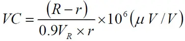
If we apply a voltage on a resistor it’s resistance will drop slightly in certain types. Therefore the resistance change is negative. The change per volt of applied voltage is called voltage coefficient, VC, and is expressed in %/V or better, μV/V. The coefficient is determined not only by the resistive material but also by the dimensions, i.e., the electrical field strength, and the time of applied voltage. Thus, MIL-STD-202, Method 309 prescribes measurements when the voltage is applied intermittently for less than 0.5 seconds. Two measurements is performed: the resistance (r) at 0.1 x rated voltage (VR) and the resistance (R) at 1.0 x VR. The voltage coefficient, VC, then is computed as:

RelatedPosts

Sulphur-Resistant Film Resistors

Designing with High Voltage Resistors: 10 Top Tips for Success

Overcoming the Challenges of Using Sub-Milliohm SMD Current Sense Chip Resistors

This image has an empty alt attribute; its file name is EQ-R1_13.jpg
resistor voltage dependence equation [1]

If we disregard pure metallic resistive elements common values of the voltage coefficient are between –10 and –100 μV/V. The voltage dependence is negligible for resistance values below 1000 ohms.

An evident voltage dependence combined with AC voltages will cause distortion and a third harmonic attenuation.

Frequency Dependence

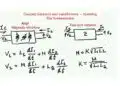
A resistor has a certain parasitic degree of both capacitance and inductance. Between the turns there is a certain capacitive connection. Inductance appears already in a straight lead, approximately 1 nH/mm of length but is amplified by the coil action from windings and spiraled patterns. In carbon composition resistors only capacitance emanating from the multitude of parallel current paths manifests itself.

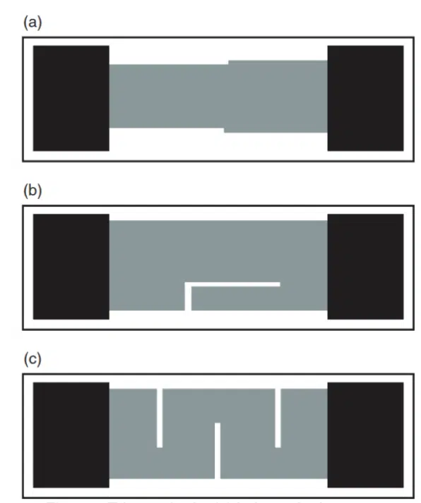
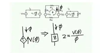
Figure 1. shows the equivalent circuit being simplified to models for high and low resistance values.
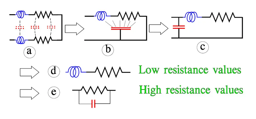
This image has an empty alt attribute; its file name is R1_17.jpg
Figure 1. Examples of equivalent circuits for resistors in different degrees of simplification
  • a) Small sizes
  • b) low R-value
  • c) Chip design
  • d) Small or no lead wire (SMD)
  • e) Even body

The frequency dependence of resistance decreases if the resistors:

  1. have small dimensions.
  2. have a low resistance value.
  3. are of a thin film design. Even a thick film design is favorable.
  4. have as short a lead as possible, like SMDs.
  5. are geometrically even, i.e., without sudden geometrical changes along the resistor body.

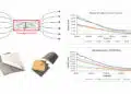
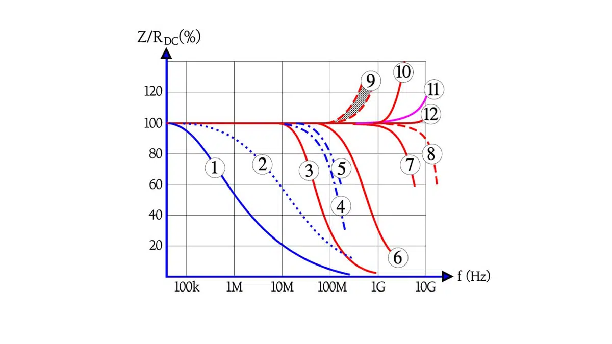
How the frequency dependence may influence the impedance is shown in Figure 2.

This image has an empty alt attribute; its file name is R1_18.jpg
Figure 2. Examples of resistor frequency dependence as the ratio of AC impedance through DC resistance for some different resistor types

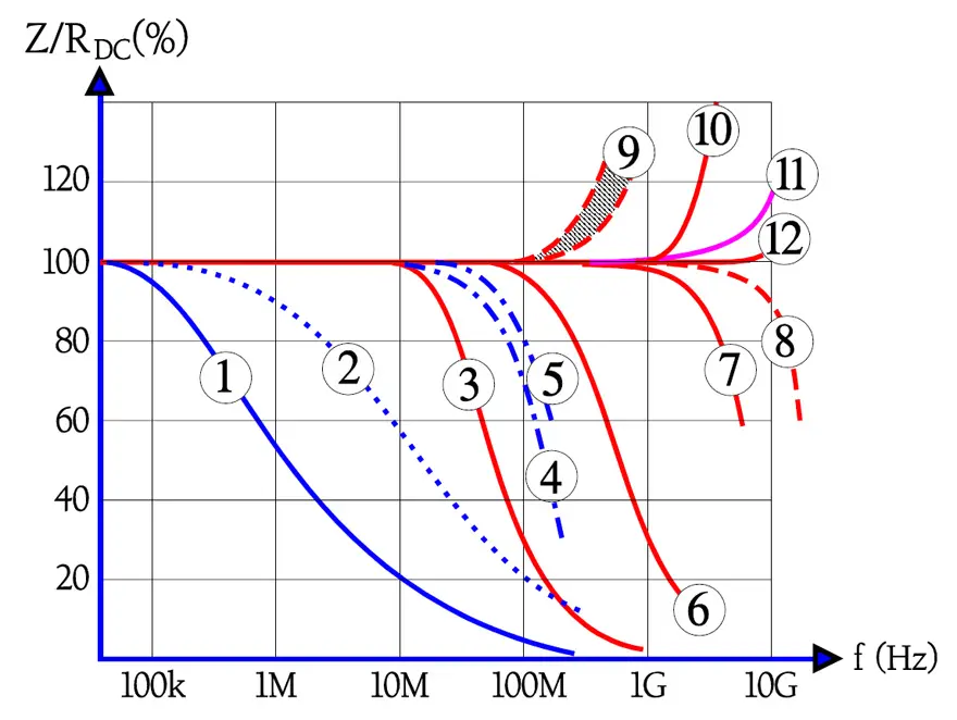
  1. Carbon composition, ¼ W, 1 MW.
  2. Carbon composition, ¼ W, 100 kW.
  3. Chip, thick film, EIA size 0603, 100 kW; c » 0.05 pF; L » 0.4 nH.
  4. Metal glaze or metal film, DIN size 0207, 100 kW; c » 0.4 pF.
  5. MELF, DIN size 0204, 10 kW.
  6. Chip, thick film, EIA size 0603, 10 kW; c » 0.05 pF; L » 0.4 nH.; Chip, metal foil, EIA size 1210, 10 kW.
  7. Chip, thick film, EIA size 0603, 1 kW; c » 0.05 pF; L » 0.4 nH.
  8. MELF, DIN size 0102, high frequency design, 10 W;  c » 0.035 pF; L » 0.8 nH.
  9. MELF, DIN size 0204, 10 W.
  10. Chip, thick film, EIA size 0603, 10 W; c » 0.05 pF; L » 0.4 nH.
  11. Chip, thin film, EIA size 0603, 100 W; c » 0.035 pF; L » 1.2 nH.
  12. Chip, thick film, EIA size 0603, 100 W; c » 0.05 pF; L » 0.4 nH.

The examples in Figure 2. represent a guide only. They are taken from major manufacturers’ data sheet. Note how the resistance value of an otherwise equivalent component influences the parameters: No. 3, 6, 7, 10 and 12. Another example, No. 8, shows a MELF component that, by means of a specific spiraling technique, is given excellent high frequency characteristics. Generally the frequency dependence of the different resistor materials can be divided into three groups:

TechnologyFrequency Dependence
Carbon compositionhigh
Metal glaze, cermet, thick filmmoderate to low
Metal film, metal oxide and carbon filmlow
resistors frequency dependence

Film resistors may approximately be classified as follows:

  • values < 100Ω are inductive.
  • values between 100 and 470Ω are practically true resistive.
  • values above 470Ω are capacitive.

Thin Film Chip High Frequency Resistors

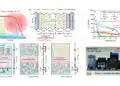
As the industry extends products above the GHz range (5G), an understanding and improvement of resistors especially in thin films products’ performance needs to be considered.

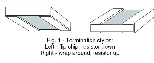
Performance of thin film resistors at high frequency is dependent on the case size, trim method, part value and termination style. The reduction in parasitic impedance for smaller cases sizes is consistent with the smaller landing pads and device dimension.
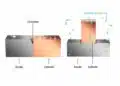
Termination style:

Figure 3. Termination style examples; source: Vishay
Table 1. example of chip resistors parameters and its parasitic coefficients; source: Vishay

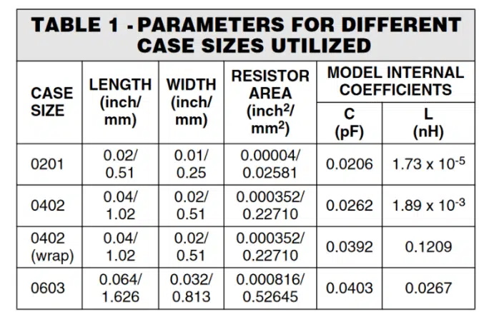
The large change between 0201 and the 0402 and 0603 can be related to significant reduction in maximum resistor area. The ratios of the maximum areas for the resistors by case size (0603 : 0402 : 0201) are 1 : 2.32 : 20.4. The small change in device area for the 0402 and 0603 case sizes is most likely related to the small differences and occasional reversal in the device performance.
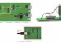
Trim method:

Figure 4. Resistor trim methods: (a) balanced edge sense,(b) L-cut, and (c) S-cu; source: Vishay
Figure 5. Comparison of trim methods for the (a) 0402and (b) 0603 case sizes. The edge sense trim has the best impedance performance; source: Vishay

Related

Recent Posts

Modeling and Simulation of Leakage Inductance

9.5.2025
1

Murata and NIMS Built New Database of Dielectric Material Properties

5.5.2025
44

Shielding Cabinets

29.4.2025
17

Magnetic Shielding and Magnetic Shielding Sheets

29.4.2025
25

Corrosion its Development and Prevention

26.4.2025
25

Housing EMC Requirements, Issues and Solutions

26.4.2025
39

Hybrid Electrochemical Electrolytic Capacitor Provides High Frequency and High Capacitance Performance

25.4.2025
47

Non-Magnetic Interconnects

23.4.2025
13

RF Inductors Key Characteristics and Applications

17.4.2025
55

Electromagnetic Emissions Leakage in Enclosures

14.4.2025
40

Upcoming Events

May 14
11:00 - 12:00 CEST

Reliable RIGID.flex PCBs for Critical Applications – Made in Europe

May 14
17:00 - 17:30 CEST

Calculating Foil Winding Losses with AI

May 28
16:00 - 17:00 CEST

Power Over Data Line

View Calendar

Popular Posts

  • Buck Converter Design and Calculation

    0 shares
    Share 0 Tweet 0
  • Boost Converter Design and Calculation

    0 shares
    Share 0 Tweet 0
  • Tariffs Crush Sales Sentiment in April 2025 ECST Results

    0 shares
    Share 0 Tweet 0
  • Flyback Converter Design and Calculation

    0 shares
    Share 0 Tweet 0
  • What is a Dielectric Constant and DF of Plastic Materials?

    4 shares
    Share 4 Tweet 0
  • Dual Active Bridge (DAB) Topology Explained

    0 shares
    Share 0 Tweet 0
  • LLC Resonant Converter Design and Calculation

    0 shares
    Share 0 Tweet 0
  • Ripple Current and its Effects on the Performance of Capacitors

    3 shares
    Share 3 Tweet 0
  • SEPIC Converter Design and Calculation

    0 shares
    Share 0 Tweet 0
  • Physical Transformer Modelling in LTSpice

    0 shares
    Share 0 Tweet 0

Newsletter Subscription


Passive Components Blog

© EPCI - Leading Passive Components Educational and Information Site

  • Home
  • Privacy Policy
  • EPCI Membership & Advertisement
  • About

No Result
View All Result
  • Home
  • Knowledge Blog
  • Premium Suppliers

© EPCI - Leading Passive Components Educational and Information Site

This website uses cookies. By continuing to use this website you are giving consent to cookies being used. Visit our Privacy and Cookie Policy.
Go to mobile version