Passive Components Blog
No Result
View All Result
  • Home
  • NewsFilter
    • All
    • Aerospace & Defence
    • Antenna
    • Applications
    • Automotive
    • Capacitors
    • Circuit Protection Devices
    • electro-mechanical news
    • Filters
    • Fuses
    • Inductors
    • Industrial
    • Integrated Passives
    • inter-connect news
    • Market & Supply Chain
    • Market Insights
    • Medical
    • Modelling and Simulation
    • New Materials & Supply
    • New Technologies
    • Non-linear Passives
    • Oscillators
    • Passive Sensors News
    • Resistors
    • RF & Microwave
    • Telecommunication
    • Weekly Digest

    SEPIC Converter with Coupled and Uncoupled Inductors

    Coupled Inductors in SEPIC versus Flyback Converters

    Vishay Releases High Current 3.3 V to 36 V ESD Protection Diodes

    TDK Extends SMT Gate Drive Transformers to 1000 V

    Non-Linear MLCC Class II Capacitor Measurements Challenges

    Researchers Demonstrated HfO Anti-Ferroelectric Flexible Capacitors

    Connector Industry Achieves Double-Digit Growth

    Stackpole Unveils Metal Element High Current Chip Jumpers

    Common Mistakes in Flyback Transformer Specs

    Trending Tags

    • Ripple Current
    • RF
    • Leakage Current
    • Tantalum vs Ceramic
    • Snubber
    • Low ESR
    • Feedthrough
    • Derating
    • Dielectric Constant
    • New Products
    • Market Reports
  • VideoFilter
    • All
    • Antenna videos
    • Capacitor videos
    • Circuit Protection Video
    • Filter videos
    • Fuse videos
    • Inductor videos
    • Inter-Connect Video
    • Non-linear passives videos
    • Oscillator videos
    • Passive sensors videos
    • Resistor videos

    SEPIC Converter with Coupled and Uncoupled Inductors

    Coupled Inductors in SEPIC versus Flyback Converters

    Non-Linear MLCC Class II Capacitor Measurements Challenges

    Percolation Phenomenon and Reliability of Molded Power Inductors in DC/DC converters

    Root Causes and Effects of DC Bias and AC in Ceramic Capacitors

    How to Calculate the Output Capacitor for a Switching Power Supply

    Switched Capacitor Converter Explained

    Understanding Inductor Dot Markings and Their Application in LTspice

    Accelerating Full Bridge LLC Resonant Converter Design with Frenetic AI

    Trending Tags

    • Capacitors explained
    • Inductors explained
    • Resistors explained
    • Filters explained
    • Application Video Guidelines
    • EMC
    • New Products
    • Ripple Current
    • Simulation
    • Tantalum vs Ceramic
  • Knowledge Blog
  • Suppliers
    • Who is Who
  • Events
No Result
View All Result
Passive Components Blog
No Result
View All Result

Automotive LED Lighting Driver Explained

4.2.2020
Reading Time: 5 mins read
A A
german luxury sport car close up shot

german luxury sport car close up shot

TDK released automotive LED lighting application note related to the use of inductors.

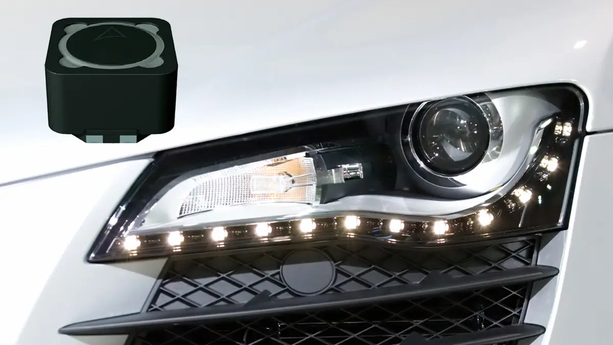
As the electrification of automobiles advances, power consumption control is becoming an increasingly important factor. LED Lighting Technology design reduces power consumption, increases lifecycle, offers design freedom and overall control. It is now used in Automotive functions including headlights and interior lighting. The TDK Group offers an extensive lineup of power inductors for use in LED drivers optimized for different systems including step-up, step-down, and step-up/step-down types.

RelatedPosts

SEPIC Converter with Coupled and Uncoupled Inductors

Coupled Inductors in SEPIC versus Flyback Converters

Vishay Releases High Current 3.3 V to 36 V ESD Protection Diodes

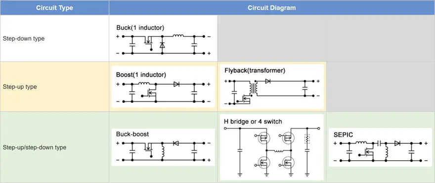
Main circuit Types used in LED drivers

Constant-current circuits are needed to operate LEDs. DC-DC converters are essential for supplying stable electric power from variable battery power. The DC-DC converters (LED drivers) commonly used are categorized into step-up type, step-down type, and step-up/step-down types depending upon the number of LEDs and system selected. Suppose the battery voltage decreases to about 6 V, the typical forward voltage for one general white LED is only 3.5 V, a step-down type converter would be used. If two to four LEDs are connected in series a step-up/step-down type is used. When five or more LEDs are connected in series, a step-up type is used. In a system with multiple functions including headlights, daytime running lights, and turn signals these circuits are then used in combination.

Table 1. Types of LED Drivers

Circuit Types for high-performance LED headlights

Typically, high-performance LED headlights use variable light distribution functions to change the range of illumination and vary the brightness.
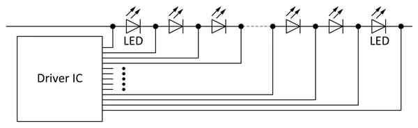
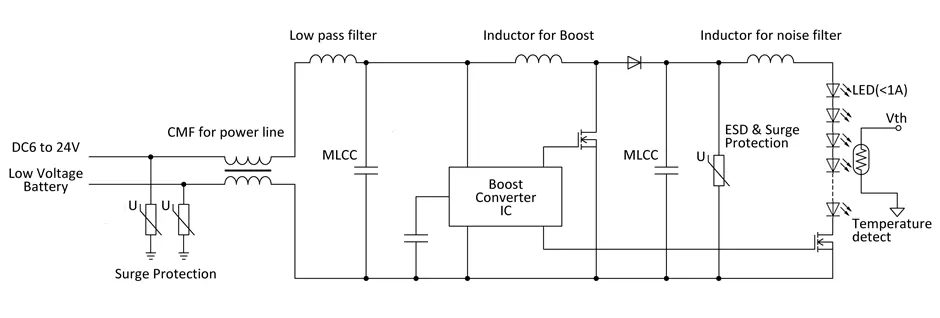
In order to vary the brightness and range of illumination, multiple LEDs are used. The luminance of each LED is then adjusted to achieve the brightness and range of illumination. Figure 1 shows a basic circuit structure. The battery voltage is increased to an approximate 40 – 60V and a buck converter supplies current to the LED.

Figure 1. LED Light Circuit Structure for Headlights

Multiple LEDs are connected in series and parallel behind the buck converter (Figure 2). The current that flows to each LED is individually adjusted to change the brightness, and in extreme cases, only a single LED is illuminated and voltage close to 60 V is applied to the output inductor of the buck converter. As a result, when used in this application, a higher comparative inductance (e.g., 100 μH) is selected. The smoothing capacitor used with the boost converter in the front end needs to maintain the current against sudden transitions in order to change the illumination range instantaneously. Typically the required range of capacitance for this smoothing capacitor is 1µF to 10µF at a withstanding voltage of 100 V.

Figure 2. Example of a Circuit in the Case Where Multiple LEDs Are Connected in Series and Parallel

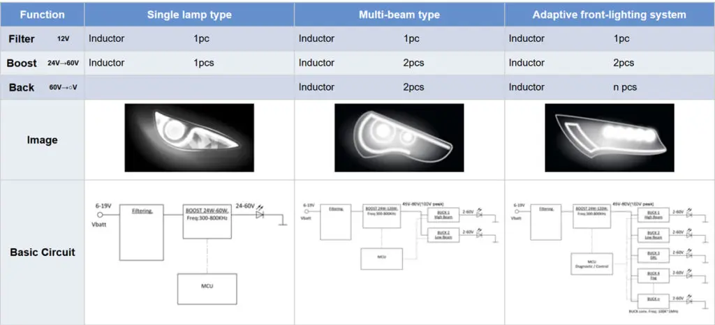
Drive circuits for LED headlights

Single lamp types use a single converter and a step-up/step-down or step-up type driver. They are used for single-function vehicle exterior lighting, interior lighting, infotainment systems, etc. Multi-beam types use two converters, a step-up circuit in the front end and a step-down circuit or constant current circuit in the back end. For vehicle exterior illumination, in the case of headlights, this structure is used to switch between high beams and low beams. Also, daytime running lights (DRL) can be added. Adaptive front lighting systems also use two converters, a step-up circuit in the front end and a step-down circuit or constant current circuit in the back end. They are used for LED headlight systems including main headlights, DRL, turn signal lights, and so on.

Table 2. LED Headlight Drive Circuits

Boost converter circuit examples

Single lamp type LED headlight functions are simple and are used to switch between high and low beams. In this case, a step-up (boost) converter of about 15 W to 30 W is used. A representative circuit structure is shown below. The output voltage is determined according to the number of LEDs in series and is in the range of about 20 V to 30 V. In the case of a step-up circuit, switching losses are high compared to a step-down circuit, and increasing the frequency is difficult. The most common frequency range is between 200 to 400 khz.

Figure 3. Example of a Boost Converter Circuit

LEDs for DRL and compact lighting applications (low power)

Systems with relatively low power including DRLs, interior illumination, back lighting, and turn signal lights use a constant current circuit or step-up/step-down circuit. The step-up/step-down circuit used in LED circuits commonly make use of SEPIC circuits.

Figure 4. SEPIC Circuit Example

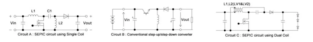
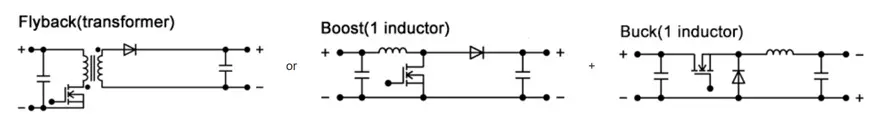
Figure 4 shows a SEPIC circuit example. Two inductors (L1 and L2) a DC cut capacitor (C1) are used. The output is controlled in the same manner as a conventional step-up/step-down converter and is determined using the following formula. In the case of a conventional step-up/step-down converter (Circuit B), the input and output polarities are reversed, but in the case of a SEPIC circuit, the polarities are the same. The fundamental relationship formula is as shown below, and the output voltage is the same as the capacitor (C1) input voltage.

V0=Vin D/(1-D) (D:duty)
VC1=Vin
VL2=VL1
IL2ave=IL1ave(1-D)/D

Based on the above relationship formula, theoretically the voltages applied to L1 and L2 (VL1 and VL2) are the same and a combination dual coil with a 1:1 winding ratio (Circuit C) can be used. In cases where a dual coil is used, the load on the core is double that compared to when a single coil is used, and an inductor with low core loss and high DC superposition is needed. The B82477D* series of TDK inductor products is suitable. These products use low-loss materials in the DR core and control for thermal generation area.

Related

Source: TDK

Recent Posts

SEPIC Converter with Coupled and Uncoupled Inductors

26.8.2025
2

Coupled Inductors in SEPIC versus Flyback Converters

26.8.2025
6

Non-Linear MLCC Class II Capacitor Measurements Challenges

19.8.2025
37

Researchers Demonstrated HfO Anti-Ferroelectric Flexible Capacitors

19.8.2025
18

Common Mistakes in Flyback Transformer Specs

15.8.2025
40

High Voltage MLCCs Meeting the Growing Demand for Efficiency in Power Conversion

12.8.2025
151

Radiation Tolerance of Tantalum and Ceramic Capacitors

8.8.2025
87

Percolation Phenomenon and Reliability of Molded Power Inductors in DC/DC converters

6.8.2025
49

Root Causes and Effects of DC Bias and AC in Ceramic Capacitors

6.8.2025
62

How to Calculate the Output Capacitor for a Switching Power Supply

6.8.2025
60

Upcoming Events

Aug 27
17:00 - 18:00 CEST

Capacitor Assemblies for High-Power Circuit Designs

Sep 3
15:30 - 17:30 CEST

How to Choose Your Magnetic Supplier

Sep 16
17:00 - 18:00 CEST

EMI Shielding Challenges

Sep 22
September 22 @ 13:00 - September 25 @ 15:15 EDT

Pre Cap Visual Inspection per Mil-Std-883 (TM 2017)

Sep 30
September 30 @ 12:00 - October 2 @ 14:00 EDT

MIL-Std-883 TM 2010

View Calendar

Popular Posts

  • Buck Converter Design and Calculation

    0 shares
    Share 0 Tweet 0
  • Boost Converter Design and Calculation

    0 shares
    Share 0 Tweet 0
  • Flyback Converter Design and Calculation

    0 shares
    Share 0 Tweet 0
  • LLC Resonant Converter Design and Calculation

    0 shares
    Share 0 Tweet 0
  • What is a Dielectric Constant and DF of Plastic Materials?

    4 shares
    Share 4 Tweet 0
  • Ripple Current and its Effects on the Performance of Capacitors

    3 shares
    Share 3 Tweet 0
  • Dual Active Bridge (DAB) Topology Explained

    0 shares
    Share 0 Tweet 0
  • How to Design an Inductor

    0 shares
    Share 0 Tweet 0
  • Core Materials, Permeability and Their Losses

    0 shares
    Share 0 Tweet 0
  • MLCC Case Sizes Standards Explained

    0 shares
    Share 0 Tweet 0

Newsletter Subscription


Passive Components Blog

© EPCI - Leading Passive Components Educational and Information Site

  • Home
  • Privacy Policy
  • EPCI Membership & Advertisement
  • About

No Result
View All Result
  • Home
  • Knowledge Blog
  • Premium Suppliers

© EPCI - Leading Passive Components Educational and Information Site

This website uses cookies. By continuing to use this website you are giving consent to cookies being used. Visit our Privacy and Cookie Policy.
Go to mobile version