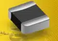


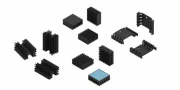


Bourns has released the BTJ Series thermal jumper chips, a family of surface‑mount thermal links designed to move heat efficiently while maintaining electrical insulation between circuit nodes.
These components target compact, thermally stressed electronics where designers need a controlled thermal path without creating a conductive or capacitive shortcut.
Key features and benefits
The BTJ thermal jumper chips combine high thermal conductivity with very low capacitance and high insulation resistance, which makes them suitable for sensitive mixed‑signal and high‑frequency designs.
Key characteristics of the BTJ Series include:
- High thermal conductivity using an aluminum nitride (AlN) ceramic with a typical value of 170 W/mK, enabling effective heat spreading from hot components into copper planes or heatsink structures.
- High insulation resistance and dielectric withstand voltages from more than 1.5 kVac RMS up to more than 5.0 kVac RMS (60 Hz), depending on the case size, allowing use between galvanically isolated nodes or across safety‑relevant creepage distances.
- Low capacitance, specified in the sub‑picofarad to low‑picofarad range (approximately 0.07 pF to 0.26 pF), which helps avoid unwanted coupling in RF, high‑speed digital, and precision analog circuits.
- An operating temperature range from −55 °C to +155 °C, supporting demanding automotive, industrial, and power electronics environments.
- RoHS‑compliant* and halogen‑free** construction, simplifying environmental compliance and material declaration processes for OEMs.
Compared to ad‑hoc thermal vias or simple copper jumps, a dedicated thermal jumper chip offers a defined thermal resistance and dielectric rating, allowing more predictable thermal modelling and safer layouts in high‑density boards.
Typical applications
The BTJ Series is aimed at applications where heat must be transferred away from a hot component while keeping functional isolation or measurement accuracy intact.
Representative use cases include:
- Power supplies and switching power supplies, where BTJ elements can bridge thermally from power semiconductors or magnetics to copper pours or heatsinking regions without tying different potentials together.
- DC‑DC converters and other power conversion stages that require temperature management around MOSFETs, GaN devices, rectifiers, or transformers in limited PCB area.
- RF and GaN amplifiers, where the low capacitance of the BTJ device helps preserve RF performance while still providing an effective thermal path from the device to a thermal pad or ground region.
- Various automotive and industrial ECUs that need to conduct heat away from microcontrollers, ASICs, or power drivers while respecting isolation requirements and EMC constraints.
- Pin diodes, laser diodes, and other optoelectronic or sensing devices where thermal stabilization is critical to maintain output characteristics and lifetime.
- Data servers and high‑density computing boards, where BTJ chips can be used to fine‑tune local temperature distribution between hot spots and large copper areas.
In temperature sensing circuits, the BTJ can be used between a heating element and a temperature sensor so that the space between them is filled with a thermally conductive yet electrically insulating material, enabling more accurate and repeatable heat detection behaviour at the system level.
Technical highlights
From a technical perspective, the BTJ Series behaves as a well‑specified thermal resistor with very low electrical coupling and high dielectric strength. The table below summarizes the key parameters provided for each part number:
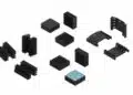
- Available EIA sizes (inches): 0508, 0603, 0612, 1206, 1225, and 2512, giving layout flexibility from very compact footprints to relatively large thermal links for higher heat flow.
- Thermal resistance values per type, for example:
- BTJ050820T100 (0508): 6 °C/W
- BTJ060320T100 (0603): 20 °C/W
- BTJ061225T100 (0612): 4 °C/W
- BTJ120625T100 (1206): 16 °C/W
- BTJ122525T200 (1225): 4 °C/W
- BTJ251225T200 (2512): 16 °C/W
- Corresponding thermal conductance values, given in mW/°C, such as 160, 50, 250, or 63 mW/°C, which make it straightforward to plug these parts into thermal simulations or hand calculations. In practical terms, a lower thermal resistance or higher thermal conductance value means more heat can be transferred for a given temperature gradient.
- Capacitance values for each part, typically in the order of 0.07 pF or 0.26 pF, which are low enough that they generally do not disturb signal integrity in most RF and high‑speed digital designs.
- Dielectric withstand voltages:
- 1.5 kVac RMS for most smaller case sizes,
- 3.0 kVac RMS for the 1206 type,
- 5.0 kVac RMS for the 2512 type, enabling use across reinforced insulation distances where appropriate PCB layout rules are followed.
Exact numerical values and tolerances for these parameters should be taken from the latest manufacturer datasheet to ensure correct use in safety‑critical and highly regulated designs.
Availability and part numbers
The BTJ Series is introduced as a defined family of thermal jumper chips with six main part numbers, each tied to an industry‑standard SMD footprint.
Available types as given in the release include:
- BTJ050820T100 – EIA 0508 size, low thermal resistance variant suitable for moderate heat flows on relatively small pads.
- BTJ060320T100 – EIA 0603 size, providing a higher thermal resistance for localized thermal management in very compact circuits.
- BTJ061225T100 – EIA 0612 size, offering a low thermal resistance with an elongated footprint, useful for bridging between wider copper areas.
- BTJ120625T100 – EIA 1206 size, balancing board space and thermal performance for general‑purpose power and signal boards.
- BTJ122525T200 – EIA 1225 size, a larger area part optimized for higher thermal conductance where more heat needs to be moved.
- BTJ251225T200 – EIA 2512 size, combining larger area with higher dielectric withstand voltage for demanding isolation and thermal tasks.
For procurement and qualification purposes, designers and buyers should refer to the dedicated BTJ Series datasheet and product selector on the manufacturer website, where packaging quantities, detailed tolerances, and ordering codes are typically provided.
Design‑in notes for engineers
Because the BTJ Series behaves like a thermal jumper rather than an electrical resistor, it should be treated in the PCB layout as a controlled thermal path between a heat source and a cooler region.
Practical design‑in considerations:
- Pad layout and copper connection:
- Use generous copper areas connected to the “cold” side to fully benefit from the thermal conductance; on multilayer boards, stitching vias to inner copper planes help spread heat.
- Follow standard SMD footprint recommendations for the specific EIA size to avoid solder voids and ensure low thermal contact resistance.
- Electrical isolation and creepage:
- Even though the BTJ device provides high insulation resistance and kVac‑level dielectric withstand, the PCB layout must still respect the relevant creepage and clearance standards for the application category.
- The low capacitance value is beneficial when placing the jumper between nodes at different potentials in high‑frequency or sensitive circuits, but residual coupling should still be considered in EMC and signal integrity simulations.
- Thermal modelling:
- The specified thermal resistance or conductance values can be inserted into compact thermal models to predict junction‑to‑ambient or case‑to‑case temperature rises.
- In practice, total thermal performance depends on solder quality, copper area, air flow, and system‑level conditions, so lab verification under worst‑case power dissipation is recommended.
- Temperature range and reliability:
- The operating range up to +155 °C allows placement close to hot components such as power switches, rectifiers, or GaN devices where board temperatures are elevated.
- By lowering the temperature rise of key components, the BTJ jumper can help extend component lifetime and improve overall system reliability, especially in power conversion, automotive, and server hardware.
Where exact de‑rating curves, surge behaviour, or long‑term reliability data are required, engineers should consult the detailed BTJ Series datasheet and associated technical notes provided by the manufacturer.
Source
This article is based on information provided in the official Bourns BTJ Series thermal jumper chip new product release and associated technical documentation, with additional engineering commentary to support design‑in decisions.