Passive Components Blog
No Result
View All Result
  • Home
  • NewsFilter
    • All
    • Aerospace & Defence
    • Antenna
    • Applications
    • Automotive
    • Capacitors
    • Circuit Protection Devices
    • electro-mechanical news
    • Filters
    • Fuses
    • Inductors
    • Industrial
    • Integrated Passives
    • inter-connect news
    • Market & Supply Chain
    • Market Insights
    • Medical
    • Modelling and Simulation
    • New Materials & Supply
    • New Technologies
    • Non-linear Passives
    • Oscillators
    • Passive Sensors News
    • Resistors
    • RF & Microwave
    • Telecommunication
    • Weekly Digest

    Smolteks CNF MIM Capacitor Break 1 µF/mm²

    Samsung Electro-Mechanics Releases 0201 X7T 1uF 6.3V MLCC for ADAS Applications

    Murata Announces 0402 Automotive Chip Ferrite Beads for V2X

    2025 Thick and Thin Film Resistor Networks Environment Overview

    Role of High-Q Ceramic Filters to Overcome GNSS Jamming

    Optimization of IoT for GEO NB-NTN Hybrid Connectivity

    TDK Releases Automotive Power-Over-Coax Inductor for Filters

    Advanced Conversion Announces Mass Production of 200C Film Capacitors

    VinaTech Supercapacitors: Enhancing Smart Meter Reliability and Efficiency

    Trending Tags

    • Ripple Current
    • RF
    • Leakage Current
    • Tantalum vs Ceramic
    • Snubber
    • Low ESR
    • Feedthrough
    • Derating
    • Dielectric Constant
    • New Products
    • Market Reports
  • VideoFilter
    • All
    • Antenna videos
    • Capacitor videos
    • Circuit Protection Video
    • Filter videos
    • Fuse videos
    • Inductor videos
    • Inter-Connect Video
    • Non-linear passives videos
    • Oscillator videos
    • Passive sensors videos
    • Resistor videos

    Understanding Switched Capacitor Converters

    Coupled Inductors Circuit Model and Examples of its Applications

    Inductor Resonances and its Impact to EMI

    Highly Reliable Flex Rigid PCBs, Würth Elektronik Webinar

    Causes of Oscillations in Flyback Converters

    How to design a 60W Flyback Transformer

    Modeling and Simulation of Leakage Inductance

    Power Inductor Considerations for AI High Power Computing – Vishay Video

    Coupled Inductors in Multiphase Boost Converters

    Trending Tags

    • Capacitors explained
    • Inductors explained
    • Resistors explained
    • Filters explained
    • Application Video Guidelines
    • EMC
    • New Products
    • Ripple Current
    • Simulation
    • Tantalum vs Ceramic
  • Knowledge Blog
  • Suppliers
    • Who is Who
  • Events
No Result
View All Result
Passive Components Blog
No Result
View All Result

Cable Spec and Wiring

20.9.2021
Reading Time: 5 mins read
A A

How to link the jacks & plugs together?

Selecting the best transmission medium for a given application is a trade-off between many important criteria, such as transmission characteristics (bandwidth, error performance,…) the distance between devices (propagation delay), physical dimensions, the speed of deployment, costs (acquisition, deployment, maintenance …)

RelatedPosts

Polymer Materials and Processing

What is RF Connector

Connector Materials and Processes

Copper wire is a good compromise as regards to the cost, the malleability and the electromagnetic properties.

Twisted Pairs
From the very beginning, the twisted pair cable has always been the exclusive link in telecommunication network applications and it remains the most popular one in most applications, even if optical fiber and satellite communication have their application fields.

A twisted pair is made up of 2 copper conductors; each conductor is insulated by a dielectric (non-conductive material) such as PVC (Poly Vinyl Chloride), Polyethylene, Teflon, fluoropolymer, or any other low smoke, fire retardant substance. This insulation layer separates the conductors from each other in such a way that the electrical circuit isn’t shorted and protects conductors against physical damage.

Fig. 2.150: Twisted pairs

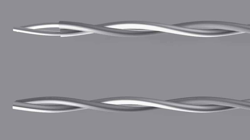
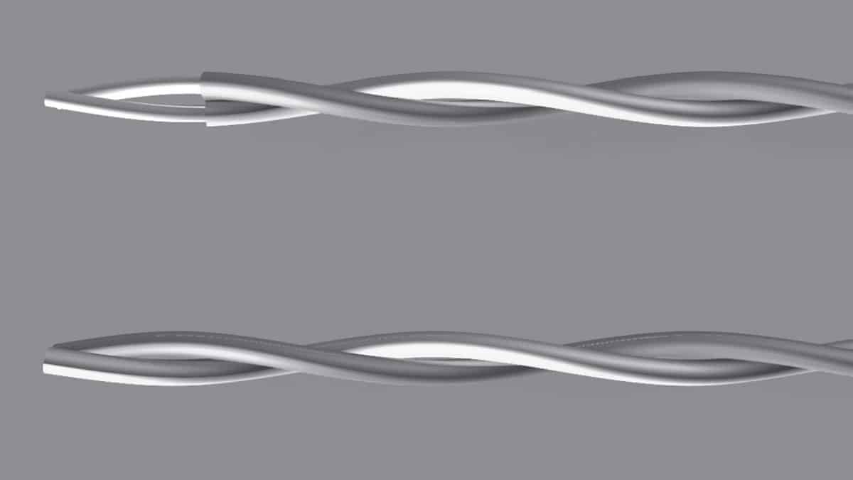
As shown on Figure 2.150, insulated conductors are twisted in a helix with a constant pitch (or distance) in order to make a 360 ° twist. This process serves to improve the signal strength over the distance, each wires carrying a similar signal. At any point of the cable, the signals are equal but opposite in polarity, which has the effect to reduce radiated energy.

A cable can comprise multiple pairs.

Shielded or Unshielded Cables
Depending on the required signal integrity level of the environment (high noise or not) and on the signal frequency, we can decide to use shielded cables or not.

Fig. 2.151: Different categories of cables

Abbreviations might be a little confusing because today, many people keep using the old convention while some others use the new one. In the description below, we decided to use the old one and to show the new one in brackets.

Here are the most popular designation according to ISO/IEC 11801.

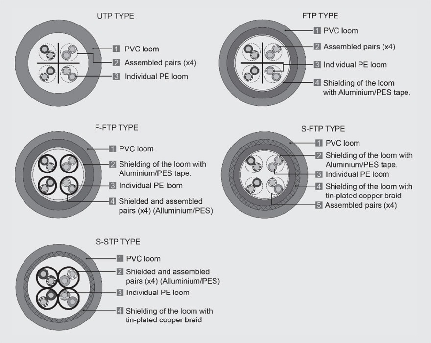
UTP (U/UTP): Unshielded Twisted Pair (unshielded cable/unshielded twisted pairs)

FTP (F/UTP): Foiled Twisted Pair (foiled cable/unshielded twisted pair). Cable type in which an overall metal foil encloses all twisted conductor pairs; then, the metal foil is encased in a thermoplastic jacket (most common type).

STP (U/FTP) Shielded Twisted Pair (unshielded cable/foiled twisted pairs). Cable type in which each of the twisted conductor pairs are enclosed by a foil screen and all pairs are surrounded by a thermoplastic jacket.

SFTP cat5e (SF/UTP) Shielded Foiled Twisted Pair. Only the external part is shielded by an Aluminium screen and a Tin/Copper foil.
Twisted pair are not shielded. This category is confusing and can be mixed with FTP.

SFTP cat6/7 & more (S/FTP or SSTP) Shielded Foiled Twisted Pair. Cable type in which each of the twisted conductor pairs are enclosed by a foil screen and then all pairs are surrounded by a braid screen and an overall thermoplastic jacket.

Here again it’s confusing because SFTP cat5 & cat6 are different therefore many people prefer to keep SFTP for cat5e only and to use SSTP for cat6. Best is certainly to use SF-UTP in cat5e and S/FTP in cat6 to make it clearer.

FFTP (F/FTP) Foiled Twisted Pairs. Best possible shielding where both twisted pairs and overall cable are surrounded by an aluminium screen.

Deciding whether you need to shield the wires or not is not easy. It’s not only about the higher cost that it implies, but also about the cable rigidity and its installation which becomes drastically more complicated with the rigidity induced by more shielding. Shielding must also be carefully protected during installation in order not to get damaged; therefore, the question “do I really need this shielding” is everything but not useless.

Cable Categories
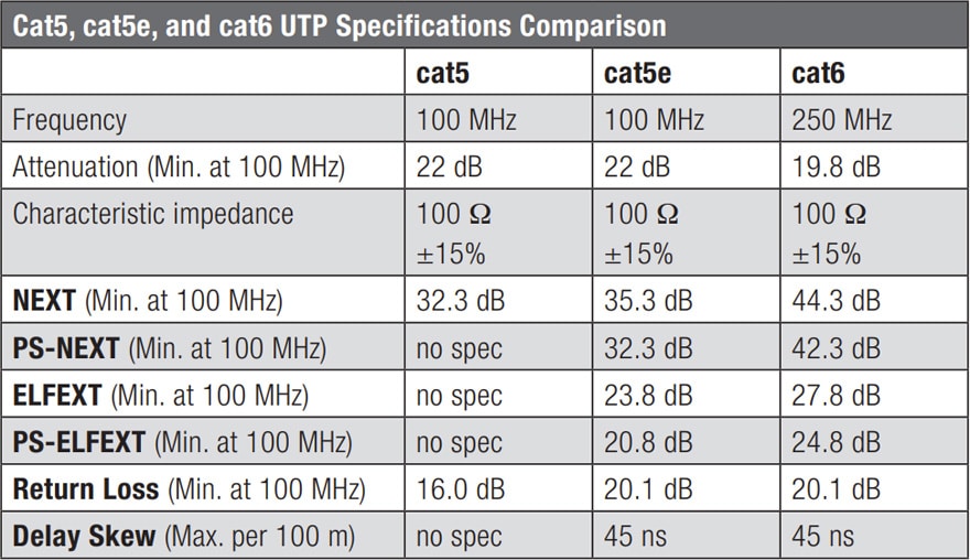
The EIA (Electronic Industries Alliance) standardized the use of UTP/STP cables by defining several categories. This standard not only defines cables, but also standards for telecommunication cabling systems. More generally, this standard defines: cable types, system architectures, distances, connectors, cable terminations, performance characteristics. The scope of this chapter does not enable to discuss everything; therefore, we will summarize the cable types, performances and connectors (Table 2.16).

Tab. 2.16: Cable categories

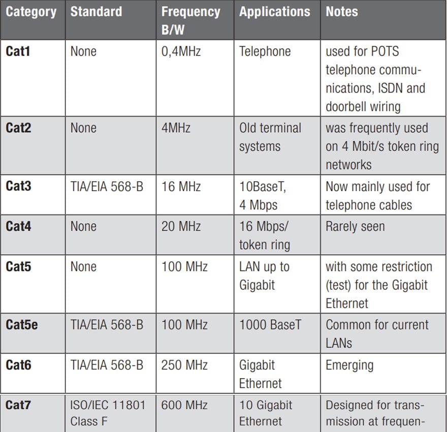
Performance characteristics are not given for each category. Some parameters such as return loss, delay skew, … are not so critical for a low frequency signal.

TIA/EIA provides a set of specifications for cables that are only suitable for high speed systems (e.g. Gigabit Ethernet), as described in Table 2.17.

Tab. 2.17: High frequency specifications

Ethernet Terminations and Wiring Color Codes
Depending on the application, the cable termination is often an issue, especially when interoperability with another system is required.

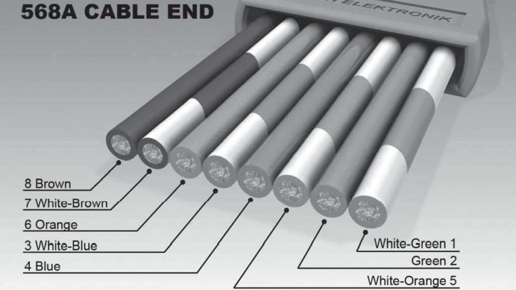
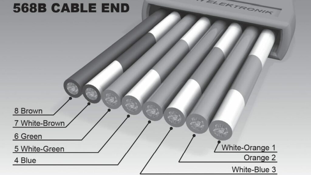
To follow protocols like Ethernet each pin needs to be wired with specific colours. In this case there are two standard layouts as follows:

Fig. 2.152: TIA/IEA 568A
Fig. 2.153: TIA/IEA 568B

A straight through cable will have the same termination at both ends while a cross over cable will mix two terminations. What for?!

If you compare both wiring, you can easily see that the only difference is that orange and green pairs are swapped, nothing else. Using a crossover cable means that Tx and Rx pairs are reversed. The reason is that before auto MDI/MDIX capabilities became widespread, a cross over cable was necessary to interconnect similar network equip ment (hub to hub …). These cables are still used sometimes to connect two computers or to link industrial equipment which are not able to swap Tx and Rx when the signal arrives on Tx; however, most of today’s communication equipment can automatically re-configure themselves (switching Tx and Rx).

Related

Source: Wurth elektronik

Recent Posts

Non-Magnetic Interconnects

23.4.2025
22

10 Tips for Ensuring Reliability of Discrete Wire Assemblies

20.2.2025
53

Polymer Materials and Processing

31.1.2025
38

Basic PCB Technology Overview

17.12.2024
15

What is RF Connector

17.12.2024
7

Creepage and Clearance of Connector

16.10.2023
14

Microwave Multi Line Connectors Mounting and Handling Precautions

17.12.2024
2

BASIC PCB Design Rules – Layout

17.12.2024
24

MEMR RF Relay for Space Compact Redundancy Ring

17.12.2024
2

Connector Temperature Rise and Derating

13.1.2023
17

Upcoming Events

Jun 24
16:00 - 17:00 CEST

Limitations of PSFB converters and improvements by a variable inductor ft. Sam Ben-Yaakov

Jun 24
17:00 - 18:00 CEST

Ultra-Compact and Efficient Switched-Capacitor Power Converters

Jul 23
13:00 - 14:00 CEST

PCB design for a Smartwatch

View Calendar

Popular Posts

  • Buck Converter Design and Calculation

    0 shares
    Share 0 Tweet 0
  • Boost Converter Design and Calculation

    0 shares
    Share 0 Tweet 0
  • Flyback Converter Design and Calculation

    0 shares
    Share 0 Tweet 0
  • What is a Dielectric Constant and DF of Plastic Materials?

    4 shares
    Share 4 Tweet 0
  • LLC Resonant Converter Design and Calculation

    0 shares
    Share 0 Tweet 0
  • Ripple Current and its Effects on the Performance of Capacitors

    3 shares
    Share 3 Tweet 0
  • How to Design an Inductor

    0 shares
    Share 0 Tweet 0
  • Dual Active Bridge (DAB) Topology Explained

    0 shares
    Share 0 Tweet 0
  • SEPIC Converter Design and Calculation

    0 shares
    Share 0 Tweet 0
  • Flying Capacitors Explained

    0 shares
    Share 0 Tweet 0

Newsletter Subscription


Passive Components Blog

© EPCI - Leading Passive Components Educational and Information Site

  • Home
  • Privacy Policy
  • EPCI Membership & Advertisement
  • About

No Result
View All Result
  • Home
  • Knowledge Blog
  • Premium Suppliers

© EPCI - Leading Passive Components Educational and Information Site

This website uses cookies. By continuing to use this website you are giving consent to cookies being used. Visit our Privacy and Cookie Policy.
Go to mobile version