Passive Components Blog
No Result
View All Result
  • Home
  • NewsFilter
    • All
    • Aerospace & Defence
    • Antenna
    • Applications
    • Automotive
    • Capacitors
    • Circuit Protection Devices
    • electro-mechanical news
    • Filters
    • Fuses
    • Inductors
    • Industrial
    • Integrated Passives
    • inter-connect news
    • Market & Supply Chain
    • Market Insights
    • Medical
    • Modelling and Simulation
    • New Materials & Supply
    • New Technologies
    • Non-linear Passives
    • Oscillators
    • Passive Sensors News
    • Resistors
    • RF & Microwave
    • Telecommunication
    • Weekly Digest

    Panasonic High Precision Chip Resistors Bridge Gap Between Thin and Thick Technology

    Wk 13 Electronics Supply Chain Digest

    Samsung Introduces 35V MLCCs Flying Capacitors for USB PD Fast Charging

    New J‑STD‑075B Standard Elevates Process Sensitivity Classification for Passive and Solid-State Components

    Modelithics Expands COMPLETE+3D Library for Ansys HFSS

    DigiKey Launches “Engineering Unlocked” Video Series

    Equivalent Circuit Constants of Crystal Units Explained

    Vishay Releases Compact High‑Accuracy Hall Effect Linear Position Sensor

    Nanocrystalline Cores for Low‑Loss MHz Chip Inductors

    Trending Tags

    • Ripple Current
    • RF
    • Leakage Current
    • Tantalum vs Ceramic
    • Snubber
    • Low ESR
    • Feedthrough
    • Derating
    • Dielectric Constant
    • New Products
    • Market Reports
  • VideoFilter
    • All
    • Antenna videos
    • Capacitor videos
    • Circuit Protection Video
    • Filter videos
    • Fuse videos
    • Inductor videos
    • Inter-Connect Video
    • Non-linear passives videos
    • Oscillator videos
    • Passive sensors videos
    • Resistor videos

    Transformer-Based Power-Line Harvester Magnetic Design

    Thermal Modeling of Magnetics

    Standard vs Planar LLC transformers Comparison for Battery Chargers

    How Modern Tools Model Magnetic Components for Power Electronics

    Advanced Loss Modeling for Planar Magnetics in the Frenetic Planar Tool

    2026 Power Magnetics Design Trends: Flyback, DAB and Planar

    Enabling Software‑Defined Vehicle Architectures: Automotive Ethernet and Zonal Smart Power

    Calculating Resistance Value of a Flyback RC Snubber 

    One‑Pulse Characterization of Nonlinear Power Inductors

    Trending Tags

    • Capacitors explained
    • Inductors explained
    • Resistors explained
    • Filters explained
    • Application Video Guidelines
    • EMC
    • New Products
    • Ripple Current
    • Simulation
    • Tantalum vs Ceramic
  • Knowledge Blog
  • DossiersNew
  • Suppliers
    • Who is Who
  • PCNS
    • PCNS 2025
    • PCNS 2023
    • PCNS 2021
    • PCNS 2019
    • PCNS 2017
  • Events
No Result
View All Result
Passive Components Blog
No Result
View All Result

Capacitor Coupling for Minimum Impedance

30.3.2022
Reading Time: 4 mins read
A A

source: signal integrity journal article

January 2, 2018, Anto Davis and Steve Sandler. A negative coupling coefficient to optimize capacitor placement may not always lead to lower impedance.
It is well known that the mounting loop of a capacitor owns the major share in parasitic inductance [1]. A practical capacitor when mounted in a printed circuit board has parasitic inductance (L) associated with it. Its equivalent circuit is a series RLC circuit where R represents the loss associated with the capacitor (C). It has a self (series) resonant frequency given byabove which it acts as an inductance. Other important contributors to the parasitic inductance are ESL and plane spreading inductance.

RelatedPosts

Rohde & Schwarz Introduces New Family of High Performance LCR Meters

Supercapacitor Balancing Methods

A mounting loop is formed by the two vias connecting a capacitor to the power-ground planes. A small form factor capacitor reduces this area and helps to minimize the parasitic inductance. Closer power-ground planes reduce the plane spreading inductance.

Geometry for Negative Coupling Coefficient

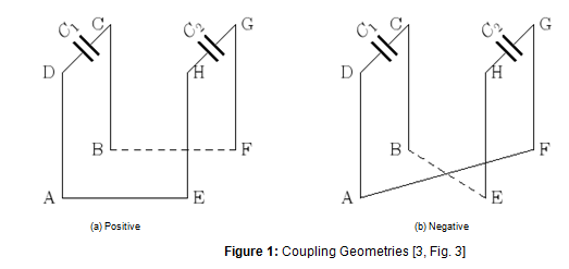
With two capacitors in parallel, we can generate a negative coupling coefficient to reduce the parasitic inductance. This is shown in Figure 1. Points A and E are on the same plane and points B and F are on the same plane. Assume that the planes are power and ground separated by thin dielectric of thickness (2-3 mils).

Figure 1(b) shows the geometrical connection for negative coupling coefficient (M and k are negative). When power and ground planes are present, this geometry can be achieved by changing via locations; B and E are on the same plane and A and F are on the same plane.

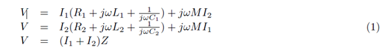
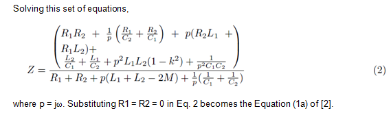
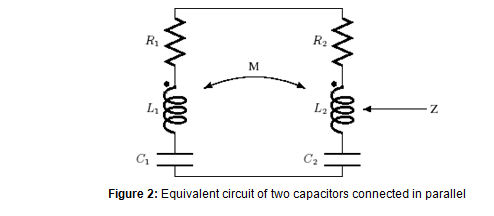
Figure 2 shows the equivalent circuit diagram of two capacitors in parallel. Writing equations for it,

1. Identical Capacitors

For large values of w, the Eq. 2 becomes the classic equation of coupled parallel inductors.

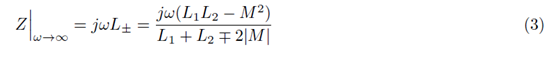
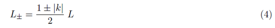
where + and – signs indicate positive and negative couplings. For equal loop areas (L1 = L2 = L), inductance is given by,

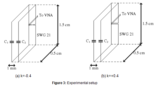
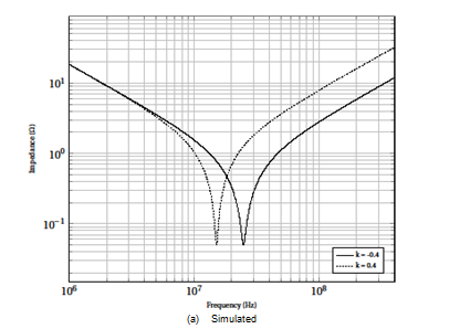
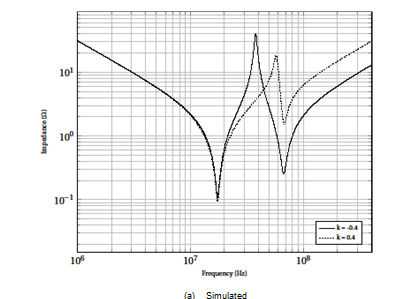
Experiments are conducted with two ceramic disc type capacitors of values C1 = C2 = 4.7 nF. Measurement with a capacitor meter gives their values as 4.30 nF. The leads are cut and made with insulated copper wire of SWG 21 (diameter = 0.813 mm). Leads make a loop of area 1.5 cm _ 0.5 cm. The measurement device is Rohde & Schwarz vector network analyzer (VNA). The scattering parameters measured are converted to impedance values. VNA is set with the following values: Resolution band width (RBW) = 10 Hz; number of points = 1000; and power = -15 dBm. Two loops are kept at a distance of 1 mm (edge to edge). The coupling coefficient between the loops (k = M/L) is calculated to be 0.4 where L is 17.6 nH and M is 6.97 nH [2]. Simulation and experimental results are shown in Fig. 4(a) and Fig. 4(b) respectively. At 100 MHz, inductance is 2.5 times (8 dB) lesser than that for positive coupling case.

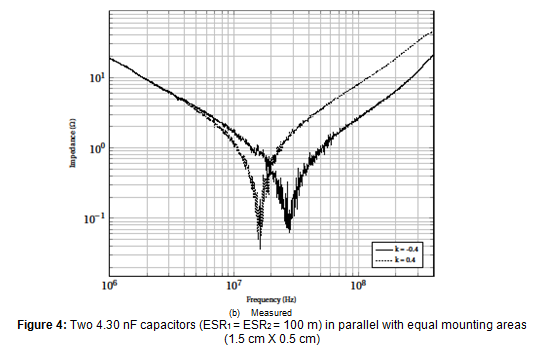
No surprises until here. How about the case where the two capacitor values are different?

Non-identical Capacitors

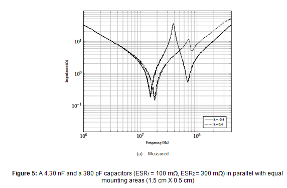
When the capacitor values are different, the parallel combination produces antiresonance peaks as shown in Figure 5. The anti-resonance peak is lower for the positively coupled case. It is assumed that the capacitors have nearly equal mounting inductance, and their sizes are comparable. Experiments are conducted for the same values of the previous experiment, except that one capacitor is changed to 390 pF. A measurement with capacitance meter gives 380 pF for this capacitor. Experimental results (Figure 5(b)) shows that the antiresonance peak is lower for positively coupled case by 3.2 times. When both the capacitors become inductive, the equivalent inductance is lower for negative coupling case.

Summary

A negative coupling coefficient produces a larger anti-resonant peak compared to a positive coupling coefficient, even though the equivalent inductance is lower. Multiple anti-resonant peaks are capable of generating rogue waves [7, 8], and suppressing them are becoming more and more important. For low noise circuits, power distribution network (PDN) resonance is an important design issue, and should be suppressed!

How about the tolerance of two identical ceramic capacitors connected in parallel? `It depends’ on the type of capacitors that determines the capacitance variations. Plotting eq. (2) with worst-case values will give the answer. Authors leave this to the curious reader to explore!

A. K. Davis (ECE, GeorgiaTech, Atlanta, USA) & S. M. Sandler (Picotest, Phoenix, AZ 85085, USA)

2. References

[1] Roy, T., Smith, L., and Prymak, J.: `ESR and ESL of ceramic capacitor applied to decoupling applications’, IEEE 7th Top. Meet. Elect. Perform. Electron. Packag., 1998, pp. 213-216.

[2] Paul, C. R.: `Effectiveness of multiple decoupling capacitors’, IEEE Trans. Electromagn. Compat., 1992, 34, (2), pp. 130-133.

[3] Davis, A.K.: `Effect of magnetic coupling between the mounting loops of two parallel capacitors on antiresonance’, IET Sci. Meas. Tech., 2016, 10, (8), pp. 889-899.

[4] Davis, A.K., and Gunasekaran, M.K.: `Microprocessor-conducted noise reduction with switched supercapacitors’, Electron. Letters, 2014, 51, (1), pp. 92-94.

[5] Novak, I., Pannala, S., and Miller, J. R.: `Overview of some options to create low-Q controlled-ESR bypass capacitors’, IEEE 13th Top. Meet. Elect. Perform. Electron. Packag., 2004, pp. 55-58.

[6] Davis, A.K.: `Effect of a magnetically coupled resistive loop on antiresonance’, Electron. Letters, 2016, 52, (13), pp. 1162 – 1164.

[7] Steve Sandler: `Target impedance based solutions for PDN may not provide realis-tic assessment’, available https://www.edn.com/design/test-and-measurement/4413192/Target-impedance-based-solutions-for-PDN-may-not-provide-a-realistic-assessment

[8] Eric Bogatin, Istvan Novak, Steve Sandler, Larry Smith, Brad Brim, and Steve Weir: `Target Impedance and Rogue Waves’, available http://www.electrical-integrity.com/Paper_download_files/DC16_TargetImpedanceRogueWaves-panel.pdf


Related

Recent Posts

Samsung Introduces 35V MLCCs Flying Capacitors for USB PD Fast Charging

27.3.2026
9

New J‑STD‑075B Standard Elevates Process Sensitivity Classification for Passive and Solid-State Components

27.3.2026
17

Modelithics Expands COMPLETE+3D Library for Ansys HFSS

27.3.2026
6

Tantalum Capacitor Anode Manufacturing Quality Management

23.3.2026
38

Middle East Conflict: The Potential Impact to Passive Components

23.3.2026
141

Murata to Decouple China Rare Earth Supply in 3 Years

19.3.2026
186
Schematic illustration of the electric double layer of porous carbon electrodes at elevated potentials in a a conventional electrolyte and b a weakly solvating electrolyte; source: authors

Researchers Presented Lignin-based Electrolyte for 4V Supercapacitors with Low Self‑Discharge

19.3.2026
26

Samsung Outlines Growth Roadmap at its 52nd General Shareholders Meeting

19.3.2026
31

Samsung Electro-Mechanics Enters LEO Satellite Market With High‑Reliability MLCCs

19.3.2026
41

Upcoming Events

Apr 21
16:00 - 17:00 CEST

Heatsink Solutions: Thermal Management in electronic devices

May 5
16:00 - 17:00 CEST

Understanding and Selecting Capacitors – Fundamentals, Technologies and Latest Trends

May 19
16:00 - 17:00 CEST

Designing Qi2 Wireless Power Systems: Practical Development and EMC Optimization

View Calendar

Popular Posts

  • Buck Converter Design and Calculation

    0 shares
    Share 0 Tweet 0
  • Boost Converter Design and Calculation

    0 shares
    Share 0 Tweet 0
  • Flyback Converter Design and Calculation

    0 shares
    Share 0 Tweet 0
  • LLC Resonant Converter Design and Calculation

    0 shares
    Share 0 Tweet 0
  • Dual Active Bridge (DAB) Topology

    0 shares
    Share 0 Tweet 0
  • MLCC and Ceramic Capacitors

    0 shares
    Share 0 Tweet 0
  • Ripple Current and its Effects on the Performance of Capacitors

    3 shares
    Share 3 Tweet 0
  • MLCC Case Sizes Standards Explained

    0 shares
    Share 0 Tweet 0
  • Capacitor Charging and Discharging

    0 shares
    Share 0 Tweet 0
  • Plastic Materials Dielectric Constant and DF

    4 shares
    Share 4 Tweet 0

Newsletter Subscription


Passive Components Blog

© EPCI - Leading Passive Components Educational and Information Site

  • Home
  • Privacy Policy
  • EPCI Membership & Advertisement
  • About

No Result
View All Result
  • Home
  • Knowledge Blog
  • PCNS

© EPCI - Leading Passive Components Educational and Information Site

This website uses cookies. By continuing to use this website you are giving consent to cookies being used. Visit our Privacy and Cookie Policy.
Go to mobile version