






Electrolytic capacitors use a thin metal oxide dielectric and a conductive electrolyte to achieve high capacitance in a compact volume.
This article explains their materials, formation, wet and solid electrolytes, cathode construction, electrical behaviour and measurement methods, with practical selection guidance for design, component and purchasing engineers.
Key Takeaways
- High capacitance density comes from a large effective anode surface area and a thin oxide dielectric. The electrolyte contacts the oxide surface; it is not the main dielectric.
- Aluminum, tantalum and niobium-based capacitors differ in anode construction, dielectric properties and cathode systems. Wet, manganese dioxide, conductive polymer and hybrid electrolytes have different loss and failure mechanisms.
- For polarized devices, the complete voltage waveform must remain within the permitted forward and reverse limits. Rated voltage, surge voltage and formation voltage are not interchangeable.
- Capacitance alone does not establish suitability. Compare ESR, impedance, ripple current, leakage, temperature dependence, endurance, startup stress and assembly requirements.
- Wet-electrolyte reformation and solid-electrolyte fault isolation are different processes. Neither makes a capacitor tolerant of unrestricted overvoltage, reverse voltage or surge current.
- Measurement conditions and lifetime models are technology- and series-specific. Use the selected part’s datasheet and application guidance rather than a universal voltage margin, storage interval or reforming procedure.
Introduction to Electrolytic Capacitors
The basic principle is to increase the effective electrode area while keeping the dielectric thin. Electrolytic construction achieves this with an etched foil or a porous sintered anode, an oxide film grown on that anode, and a conductive medium that reaches the fine surface structure.
The pores and cavities of the anode are coated with an electrically insulating oxide. A liquid, gel-like or solid electrolyte contacts the opposite side of that oxide and provides the counter-electrode connection. This arrangement makes much more of the internal surface electrically accessible than a separate rigid metal electrode could contact.
The electrolyte must not be confused with the dielectric. The oxide layer separates charge; the electrolyte provides electrical contact to its outer surface. In a wet aluminum capacitor, the electrolyte is commonly described as the real cathode, while the cathode foil provides the current-collecting connection to the external terminal. [1]
Most electrolytic capacitors are polarized because the oxide and electrode interfaces do not behave symmetrically when the voltage is reversed. Purpose-designed bipolar aluminum capacitors are an exception, but their permitted waveforms and applications still require checking. A non-polar marking does not automatically make an electrolytic capacitor suitable for continuous AC power service.
Construction of electrolytic capacitors
The construction can be considered as three connected systems. Each influences both the electrical specification and the way the capacitor responds to manufacturing, environmental and circuit stress.
- An anode with a large effective surface area and an oxide dielectric formed on that surface.
- An electrolyte that contacts the dielectric throughout the accessible surface structure.
- A cathode current collector, internal connections, external terminals, enclosure and sealing system.
The following sections explain these systems before considering leakage current, equivalent series resistance (ESR), dissipation factor (DF), frequency dependence and measurement practice. The discussion covers bulk filtering and energy storage in power circuits as well as lower-current electronic applications; suitability for rapid pulse discharge, safety-critical equipment or continuous AC operation must be established separately.
Capacitor Materials
The dielectric is an oxide of the anode material, rather than the electrolyte itself. Aluminum, tantalum and niobium-based systems use different oxides, but all depend on controlling dielectric thickness, effective area and defect levels.
Aluminum and tantalum belong to the valve metals: metals that can form adherent, electrically insulating oxide films by anodic oxidation. Aluminum electrolytics use aluminum oxide, Al2O3, and tantalum electrolytics use tantalum pentoxide, Ta2O5. Niobium-based capacitors use niobium pentoxide, Nb2O5, as the dielectric; the underlying conductive anode may be niobium or niobium monoxide, NbO. [1, 2, 3]
Relative permittivity, εr, depends on the oxide and its structure. Representative manufacturer values are approximately 8.4 for aluminum oxide and 26 for tantalum pentoxide. These are useful material comparisons, not sufficient information for predicting the capacitance or reliability of a finished component. Formation conditions, usable surface area, dielectric thickness and package construction also matter. [2]
The first-order capacitance relationship is given in Eq. (1). Here C is capacitance in farads, ε0 is the permittivity of free space, εr is relative permittivity, A is the electrically active dielectric area in square metres and d is dielectric thickness in metres.
Eq. (1) explains the two principal routes to high capacitance: increase A and reduce d. The first is achieved by etching or powder processing; the second is limited by the required voltage capability and reliability margin. The active area is also frequency-dependent in practice because resistive paths can prevent the deepest parts of a porous electrode from responding fully to a rapidly changing voltage.
Formation
A thin native oxide develops when a valve metal is exposed to air. Capacitor manufacture uses controlled electrochemical formation, also called anodic oxidation, to grow a dielectric suited to the intended voltage rating. The anode is connected positively in a formation bath, with a separate negative electrode completing the process circuit.
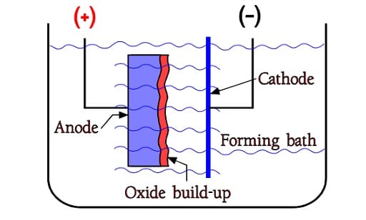
As illustrated in Figure 2, the formation process grows oxide on the anode. Dielectric thickness increases approximately with formation voltage over the useful process range. For aluminum oxide, Nichicon gives an approximate growth factor of 1.3–1.5 nm/V. This is a manufacturing relationship referenced to formation voltage, not a rule for calculating a finished capacitor’s operating rating directly. [1]
Formation voltage exceeds the eventual rated voltage by a margin chosen for the material, electrolyte, manufacturing process and reliability requirement. The margin is not a universal percentage. Solid-electrolyte processing and the subsequent ability to isolate defects differ from liquid-electrolyte construction, so formation practices cannot be transferred unchanged between them.
Maximum rated voltage is likewise not a single physical ceiling for all wet aluminum, wet tantalum or solid tantalum capacitors. It depends on the available foil or powder, oxide quality, cathode system, electrolyte, sealing and qualification. Use current series data rather than a historical technology-wide maximum.
Four voltage terms must be kept distinct: formation voltage is a manufacturing parameter; rated voltage is the specified operating rating under stated conditions; category voltage is the permitted voltage at a stated category temperature where temperature derating applies; and surge voltage is associated with a specified intermittent test or exposure. A surge rating is not additional continuous operating headroom. [1, 4, 6]
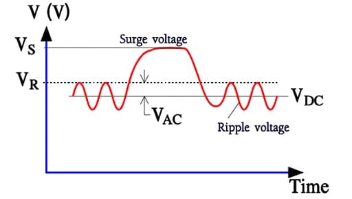
Figure 3 shows why the DC operating point alone is insufficient. For a polarized capacitor with a positive DC bias and approximately symmetrical ripple, Eq. (2) expresses the basic operating-envelope checks. VDC is the DC bias, Vripple,pk is the peak ripple amplitude, and Vallow(T) is the permitted forward voltage at operating temperature T, including the applicable category-voltage limit and the selected design derating.
Eq. (2) is not a complete transient specification. Startup overshoot, load release, shutdown, ringing and fault conditions must also be checked against the selected component’s permitted waveform. Ripple-current heating is a separate limit even when the voltage remains within the allowed envelope. Do not design intentional reverse operation into an ordinary polarized device merely because a datasheet permits a small, short reverse transient.
The polarity dependence is sometimes illustrated by a capacitor with a parallel diode, as in Figure 4. This is a qualitative warning about asymmetric conduction, not an accurate protective-clamp model. Reverse bias can increase leakage, alter the oxide and electrode interfaces, generate heat and gas in wet constructions, and cause permanent failure. The permissible reverse exposure, if any, is specific to the series, temperature, duration and circuit impedance. [1, 4, 6]
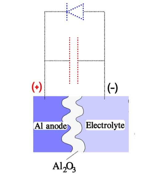
Leakage is not adequately explained by treating the electrolyte simply as an electron-deficient material or by assuming that oxygen ions pass through a crystalline grid in the same way in every capacitor. Oxide defects, interfacial barriers, electric field, temperature, polarization and electrochemical processes contribute differently in wet and solid systems. Electronic transport can include field-assisted mechanisms such as Poole–Frenkel emission; it should not be assumed to follow one universal law over the full operating range.
Surface magnification
Surface magnification is the increase in effective electrode area relative to a smooth foil or a compact body of similar external dimensions. Electrolytic capacitors obtain this area mainly by electrochemically etching foil or by sintering fine conductive powder into an interconnected porous anode.
- Etched foil: cavities and tunnels increase the surface available for oxide formation. The pore structure is selected to suit the required voltage, foil strength and manufacturing process.
- Sintered anode: a pressed powder body is heated to join particles while retaining interconnected porosity. The accessible particle surfaces are then formed and contacted by the electrolyte.
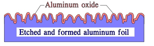
Figure 5 is schematic: practical foil has a complex sponge-like or tunnel-like structure. Etching method and penetration depth vary with the intended voltage class. Surface-enlargement factors are therefore process-specific rather than a universal maximum; they also do not necessarily equal the electrically accessible area at every frequency. [1]
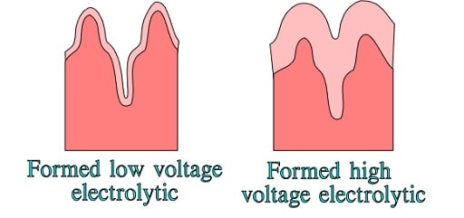
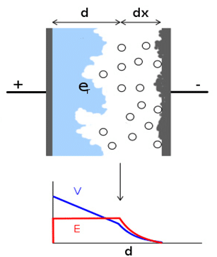
Higher formation voltage requires thicker oxide. As Figure 6 illustrates, oxide growth occupies part of the available pore space and changes the useful geometry. Very fine structures that are effective at low voltage may be unsuitable at higher voltage. Higher capacitance density therefore cannot be obtained simply by increasing etching depth without considering formation, impregnation and electrical access.
Etched foil must also be thoroughly cleaned. Residual aggressive etchants and ionic contamination can degrade leakage and reliability. High-purity anode material, controlled rinsing, clean handling and repeatable manufacturing are important quality controls; these are supplier-process and qualification matters rather than parameters that a circuit designer can infer from capacitance alone.
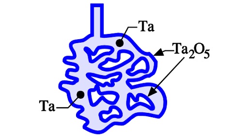
For tantalum and niobium-based powder anodes, sintering produces a continuous conductive skeleton while retaining internal surface area, as shown in Figure 7. The powder size distribution, pressing density and sintering conditions influence porosity, mechanical strength and the ability of formation and cathode materials to penetrate the structure.
NbO deserves a separate distinction: it is conductive niobium monoxide used as the anode material, whereas Nb2O5 is the insulating dielectric. Although the general construction resembles a tantalum powder capacitor, the materials and fault-arrest mechanisms are not identical. [3]
Electrolytes
The enlarged anode surface is useful only if the counter-electrode system can contact it effectively. The electrolyte must reach the accessible oxide surface, conduct current with acceptable losses and remain compatible with the dielectric, separator, connections and sealing system.
Liquid electrolytes conduct predominantly through ionic transport. Manganese dioxide and conductive polymer cathodes provide predominantly electronic conduction. These differences influence ESR, low-temperature behaviour, leakage, dielectric repair and failure response.
At low enough frequency, much of the accessible internal surface contributes to capacitance. At higher frequency, resistance along narrow pores introduces distributed time constants, so some internal area contributes less. It is therefore misleading to assume that every microscopic surface element is equally active under all measurement and operating conditions.
Wet electrolytes
A wet electrolyte needs suitable conductivity over the intended temperature range, chemical compatibility, good impregnation and acceptable vapour pressure. It also supports electrochemical repair of small dielectric defects during manufacturing ageing and subsequent operation. The actual formulation depends on voltage, temperature, lifetime and application requirements. [1]
In wet aluminum capacitors, a porous separator prevents direct metallic contact between the foils and retains electrolyte within the winding. The separator is not the primary capacitor dielectric: that function belongs to the oxide on the anode. The available electrolyte and the effectiveness of the seal are important to long-term performance.
Water content alone does not determine whether an electrolyte is good or bad. Solvents, salts, inhibitors, oxide compatibility, conductivity, corrosion behaviour and gas management must be considered together. Broad statements that one fixed water percentage defines a general-purpose electrolyte, or that all low-water formulations have the same storage life, are not suitable selection rules.
Wet tantalum capacitors commonly use an acidic electrolyte with a sintered anode and a compatible cathode and enclosure. Tantalum pentoxide is chemically resistant, but the complete component still depends on the separator or spacer materials, seals, case and internal connections. Hermetic and elastomer-sealed constructions exist and should not be treated as equivalent in environmental or reliability assessments. [6]
Historical tantalum foil constructions used separators and electrolyte systems different from those of sintered wet tantalum designs. Their construction remains useful background, but contemporary selection should be based on actual available parts rather than assuming that all wet tantalum capacitors share one internal arrangement.
Reformation, storage and dielectric repair
During storage without applied voltage, the oxide and electrolyte interfaces can change, and leakage measured at the next energisation may be higher than after stabilisation. Applying forward voltage under controlled conditions can reform affected regions of the dielectric. This does not restore electrolyte lost through evaporation, reverse corrosion, repair mechanical damage or make an aged component equivalent to a new one. [1]
Excessive leakage during reformation generates heat; electrochemical reactions can also generate gas. A stored or suspect capacitor should therefore not be connected indiscriminately to a low-impedance source at full voltage. Follow the component manufacturer’s storage and voltage-treatment instructions, including the voltage ramp or series resistance, current limit, duration, temperature and acceptance criteria.
There is no universal storage interval after which every aluminum electrolytic must be reformed, nor a universal current formula suitable for every size and voltage. Storage history, series design and the manufacturer’s recommendations determine whether treatment or replacement is appropriate. Shelf-life test duration, recommended warehouse storage and service life under ripple load are different specifications.
Small local dielectric defects may be repaired electrochemically if the fault energy remains limited and the electrolyte can support oxide growth. The initial event can nevertheless discharge energy already stored in the capacitor, while the surrounding circuit may supply additional energy. A stiff source, large parallel bank or repeated overstress can prevent a benign outcome.
This repair process should not be confused with the clearing of a metallized film capacitor or with fault isolation in a solid electrolytic. In every case, the permissible electrical stress and the consequences of a short circuit must be assessed at circuit level.
Solid electrolytes
Solid electrolytes make electrical contact with the oxide without a free liquid reservoir performing that function. The principal systems discussed here are manganese dioxide, MnO2, and conductive polymers. Their conductivity, processing and behaviour at a dielectric defect differ substantially.
Absence of a liquid reservoir removes the conventional electrolyte dry-out mechanism, but it does not establish unlimited lifetime or immunity to environmental effects. Conductive polymer properties and interfaces can change with prolonged temperature, humidity and oxygen exposure; packaging and product grade remain important. [4]
Manganese dioxide
In a conventional solid tantalum capacitor, the formed porous anode is impregnated with a manganese nitrate solution. Heating converts the precursor to manganese dioxide on the dielectric surface. Impregnation, thermal conversion and dielectric repair stages may be repeated to obtain suitable coverage and electrical properties. The precursor is manganese nitrate, not manganese nitrite. [2]
The conversion process changes material volume and subjects the oxide to thermal stress. Cathode coverage, defects and the internal conductive network must be controlled during manufacture. Neither a fixed number of conversion cycles nor a single minimum rated voltage can be applied to all manufacturers and constructions.
MnO2 has higher resistivity than conductive polymers, so the cathode can make a substantial contribution to ESR. Nevertheless, manganese dioxide tantalum capacitors remain relevant where their electrical stability, temperature capability, established qualification or other series-specific properties match the application. Low-ESR versions and multi-anode designs also exist. [2, 3]
Solid MnO2 capacitors do have a fault-isolation mechanism. Local heating at a dielectric defect can convert nearby manganese dioxide to a less conductive manganese oxide, reducing current through the affected region. This is different from rebuilding the oxide using a liquid electrolyte. [3]
The mechanism is not guaranteed to arrest a high-energy event. In a low-impedance circuit, a large surge can develop faster than isolation occurs, resulting in a permanent short circuit and potentially ignition. Voltage derating, source impedance, inrush control and the manufacturer’s surge guidance are therefore particularly important for MnO2 tantalum capacitors on power rails.
Historical solid aluminum constructions also used manganese dioxide. Their processing and voltage limitations should not be transferred to present-day aluminum polymer or hybrid products. A technology name alone does not establish an allowable operating voltage or an appropriate substitute.
Conductive polymer
Conductive polymer electrolytics replace the manganese dioxide or liquid counter-electrode system with an electrically conductive polymer. Aluminum versions may use wound or stacked foil structures; tantalum versions use a porous sintered anode. Cathode deposition can involve polymer formation within the structure or the application of a suitable polymer dispersion, depending on the manufacturing process. [4, 5]
Polymers such as PEDOT, poly(3,4-ethylenedioxythiophene), provide high conductivity and enable low ESR. Earlier constructions also used polypyrrole. The useful comparison is the finished capacitor’s ESR, impedance and ripple-current performance at the relevant frequency and temperature, not a universal improvement factor over MnO2.
Replacing MnO2 removes that cathode material’s oxygen-releasing failure mechanism and reduces the associated ignition risk. It does not make the capacitor incapable of short-circuit failure, overheating or damage from excessive current. A polymer capacitor connected to a high-energy source still needs appropriate protection and application validation. [3, 4]
Polymer cathodes can isolate a local dielectric defect through local loss of conductivity or physical separation of the conductive material around a hot spot. Again, this is not the same process as wet-electrolyte oxide reformation. Its effectiveness depends on the defect, available energy, materials and construction.
Conductive polymer tantalum capacitors generally require less voltage derating than traditional MnO2 tantalum devices, but the recommendation remains manufacturer- and series-specific. For example, the KYOCERA AVX basic guide gives typical operation at 90% of rating for products rated up to 10 V and at 80% for products rated 16 V and above, subject to temperature and individual series guidance. These thresholds must not be applied as a universal rule to all polymer capacitors. [4]
Available voltage and temperature ranges have expanded beyond early polymer products. The current KYOCERA AVX portfolio includes tantalum polymer series with ratings up to 125 V and a designated high-temperature automotive series rated to 150 °C. These are separate portfolio capabilities: a range summary does not mean that every capacitance, voltage, case size and maximum temperature is available in one part. [9]
This broader range can make polymer technology relevant to higher-voltage power rails, but suitability must be checked against operating voltage, category voltage, recommended derating, transients and capacitance availability. A 125 V catalogue rating alone is not approval for an arbitrary 100 V bus.
Moisture, reflow and thermo-mechanical stress also require attention. Molded polymer parts may have specified moisture sensitivity levels and dry-pack handling requirements, while hermetically sealed constructions can have different classifications. Follow the actual package label and datasheet for floor life, drying, reflow peak, ramp rate and permitted reflow cycles rather than assigning MSL 3 to the entire technology. [4]
Automotive-qualified polymer series incorporate product-specific provisions for their intended environment. Qualification does not remove the need to check biased humidity, temperature, vibration, endurance and assembly conditions for the application. In particular, dry-pack handling before soldering and resistance to humidity throughout service are separate issues.
Leakage can also differ from MnO2 tantalum. Some polymer products have higher specified DCL and longer stabilisation after voltage application, especially at low temperature or immediately after drying and reflow. These effects matter for battery-powered equipment, hold-up circuits and production leakage tests. Use the specific test time and limit rather than assuming that low ESR implies low leakage. [4]
Organic semiconductor electrolytes and OS-CON
Earlier organic semiconductor aluminum capacitors used materials based on TCNQ, tetracyanoquinodimethane. In those constructions, impregnation with an organic semiconductor system provided a solid conductive counter-electrode after processing.
The OS-CON name should not be used as a generic synonym for TCNQ construction. Panasonic’s technology history distinguishes the early organic semiconductor products from the later transition to conductive polymer. Present-day selection should identify the actual series and electrolyte system rather than infer internal chemistry from a historical trade name. [5]
Hybrid electrolyte: wet and solid
Conductive polymer hybrid aluminum electrolytic capacitors combine polymer and liquid electrolyte within a wound aluminum structure. The polymer provides a low-resistance conductive path, while the liquid electrolyte maintains contact and supports dielectric repair. The manufacturing details and the distribution of polymer within the winding depend on the product design. [5]
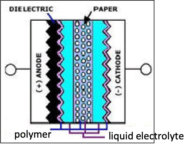
Figure 8 illustrates the combined electrolyte system. The design can offer low ESR and high ripple-current capability together with low leakage and insulation-repair behaviour. This combination is relevant to power filtering in automotive and industrial electronics, where thermal conditions, standby current and electrical stress may all influence selection. [5]
A hybrid capacitor still contains liquid electrolyte. Its service-life assessment must therefore use the hybrid series’ own endurance data and lifetime model, not an assumption of unlimited solid-state life. Nor should improved electrical performance be interpreted as unrestricted tolerance of reflow, humidity, reverse voltage or repetitive high-current pulses.
The word hybrid is also used for some wet tantalum cathode constructions. That usage describes a different internal system and must not be confused with conductive polymer hybrid aluminum electrolytics.
The Cathode and Connections
The electrolyte establishes the counter-electrode contact at the dielectric, but the current must still reach an external terminal. Cathode coatings, current collectors, tabs, welds and package geometry therefore influence ESR, inductance, thermal performance and mechanical reliability.
Cathodes in solid tantalum, niobium-based and aluminum electrolytics
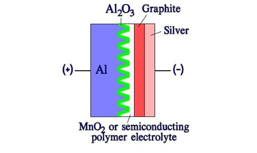
In solid electrolytics, MnO2 or conductive polymer contacts the oxide and acts as the counter-electrode material. The following illustrations show representative constructions rather than one universal arrangement for every solid electrolytic product.
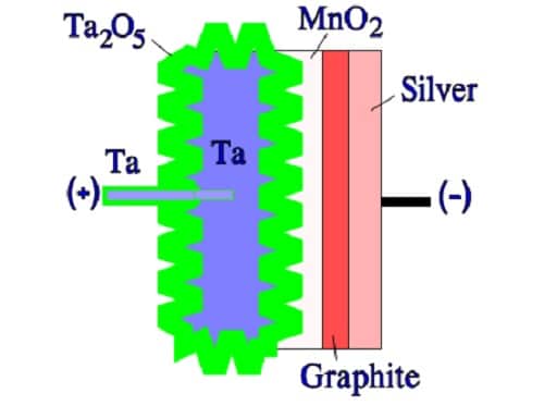
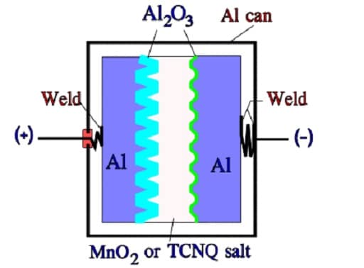
In a conventional solid tantalum construction, graphite and a silver-containing conductive layer are applied over the solid cathode material to provide a low-resistance connection to the package cathode termination. The precise attachment method may use conductive adhesive, welding, soldering or other construction-specific techniques; it should not be assumed that every external cathode lead is soldered directly to the silver layer. [2]
The tantalum anode connection is made through a tantalum wire associated with the sintered body. Depending on construction, the wire may be embedded in or welded to the anode. In foil capacitors, tabs or other collector structures connect the foils to the terminals. Their number, position and attachment quality influence resistance and inductance.
Niobium-based powder capacitors have a broadly similar layered arrangement, but NbO anodes are not simply tantalum anodes made from another metal powder. The conductive anode, Nb2O5 dielectric and interfacial sub-oxides have their own electrical and fault-arrest behaviour. [3]
Solid aluminum capacitors include both wound and stacked or laminated structures. Figure 11 represents a wound arrangement; it should not be taken to mean that every aluminum polymer capacitor uses the same separator, can or internal current path. Stacked foil and alternative terminal geometries can reduce current-path resistance and inductance without changing the basic oxide-dielectric principle. [5]
The cathode in a wet aluminum electrolytic capacitor
In a wet aluminum electrolytic, the liquid electrolyte is the counter-electrode in contact with the anode oxide. The cathode foil collects current from that electrolyte. Its surface is usually treated to provide adequate area, and its thin oxide introduces a cathode capacitance in addition to the anode capacitance. [1]
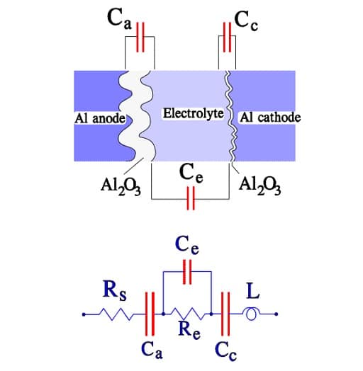
In Figure 12, Ca is anode capacitance and Cc is cathode capacitance. Rs represents the model’s dielectric and metallic-path loss contribution; Re represents electrolyte and separator-path resistance. Ce is a small capacitance associated with the electrolyte region in this extended model, and L is the inductance of the winding, connections and leads. These are equivalent-circuit elements, not separately accessible components.
At low frequency, where the simple two-capacitance description is appropriate, the anode and cathode capacitances are in series. Their combined capacitance C is given by Eq. (3).
If Cc is much larger than Ca, Eq. (3) approaches Ca, so the anode primarily determines the terminal capacitance. Cathode design still matters: a decrease in cathode capacitance, for example after inappropriate reverse or repetitive discharge stress, can reduce total capacitance. The thin native cathode oxide is not permission to operate the complete polarized capacitor continuously in reverse.
For practical circuit design, a series resistance, capacitance and inductance model is often a useful starting point over a limited frequency range. Eq. (4) gives that model, with Z the complex terminal impedance, j the imaginary unit, ω the angular frequency, f the frequency, and ESR the equivalent series resistance. C and ESR must be appropriate to the frequency and temperature being considered. [1]
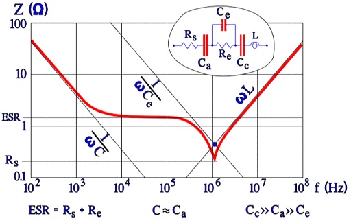
Figure 13 illustrates how the impedance departs from an ideal capacitor. At lower frequency, capacitive reactance dominates; over an intermediate region, losses can flatten the curve; at sufficiently high frequency, inductance becomes important. The curve and any minimum depend on temperature and the distributed internal structure.
In the simple series model of Eq. (4), cancellation of the inductive and capacitive reactances leaves ESR at resonance. In the extended circuit of Figure 12, a small parallel capacitive path can modify the electrolyte contribution at high frequency, but the terminal minimum is not universally equal to Rs alone. The original extended model should therefore be used as an explanatory illustration, not as a universal quantitative model.
Use measured impedance curves or a validated manufacturer model when resonance, damping or high-frequency current sharing affects the design. A room-temperature ESR value at one frequency does not describe the complete impedance spectrum, especially for wet electrolytes whose conductivity changes strongly at low temperature.
The cathode in a wet tantalum electrolytic capacitor
Wet tantalum capacitors combine a porous tantalum anode, tantalum pentoxide dielectric, liquid electrolyte and a compatible cathode system. Cathode construction can significantly influence usable capacitance, ESR, case volume and permitted reverse exposure. [6]
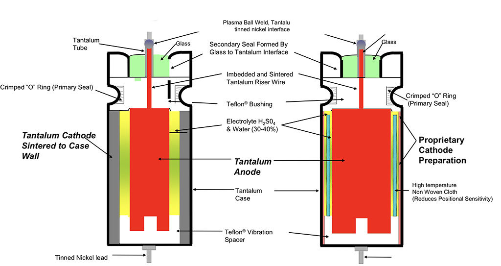
In a conventional tantalum-case design, a sintered tantalum cathode sleeve provides a large-area interface inside the case. Other designs replace that sleeve with a high-surface-area cathode coating or another proprietary cathode system, leaving more internal volume for the anode. Figure 14 compares these approaches. [6]
The resulting capacitance and energy density can be attractive for hold-up and energy-storage applications with demanding volume and reliability requirements. However, a high CV product is not the same as a high energy density: stored energy also depends on operating voltage, while usable energy depends on the permitted voltage swing and losses.
Reverse-voltage capability cannot be inferred from a tantalum case alone. Some established constructions permit specified reverse exposure, whereas other high-capacitance cathode systems restrict or prohibit continuous reverse voltage. Check the exact series, temperature, time and waveform limits. A reverse-voltage statement for one conventional construction must not be transferred to a sleeveless replacement.
Silver-case wet tantalum constructions also exist, but the conventional silver-case arrangement is not intended to tolerate reverse voltage. Case material, cathode system, seal and qualification must be identified when replacing an older part, particularly in high-reliability equipment. [6]
The expression hybrid wet tantalum may describe a specialised cathode arrangement in this family. It does not indicate the same polymer-plus-liquid electrolyte system used in hybrid aluminum capacitors. Purchasing specifications and approved alternatives should identify the complete technology rather than rely on the word hybrid.
Drawbacks of surface magnification
Increasing surface area also increases the complexity of the internal current paths. The electrolyte has finite resistance, and current must travel farther through narrow passages to reach the deepest parts of an etched foil or sintered anode.
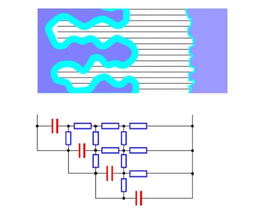
Figure 15 represents these paths as a distributed resistance-capacitance network. Surface regions close to the main conductive path have short charging time constants; deeper regions can have longer time constants because of their access resistance. As frequency increases, some regions contribute progressively less to the measured terminal capacitance.
This does not mean that the physical surface disappears. It means that the complete porous structure cannot respond instantaneously to the applied waveform. The resulting frequency dependence depends on pore geometry, cathode coverage and electrolyte conductivity, as well as dielectric behaviour.
Temperature changes the access resistance, particularly in wet electrolytes. At low temperature, increased electrolyte resistance can raise ESR and impedance and reduce the capacitance obtained at the measurement frequency. Conductive polymer can improve high-frequency capacitance retention, but it does not eliminate terminal inductance or all distributed internal effects. [1, 4]
Charge and discharge capability
A capacitor suitable for ordinary ripple filtering is not automatically suitable for repeated rapid charging and discharging. Repetitive pulse service stresses the cathode interface, foils, tabs and connections as well as the dielectric. Select a series explicitly intended or approved for the actual pulse waveform. [1]
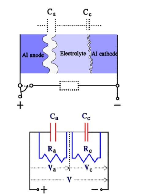
Figure 16 uses anode and cathode capacitances with associated leakage paths. If those paths are represented locally by linear resistances Ra and Rc, the steady-state voltage magnitudes Va and Vc divide approximately as shown in Eq. (5). This is a restricted explanatory model: real leakage is voltage-, temperature- and time-dependent.
The corresponding idealised capacitive charge magnitudes Qa and Qc are given in Eq. (6). Because leakage paths can transfer charge over time, these internal charge magnitudes need not remain equal after a prolonged DC bias. They should not be confused with the equal incremental charge in an ideal series connection without leakage.
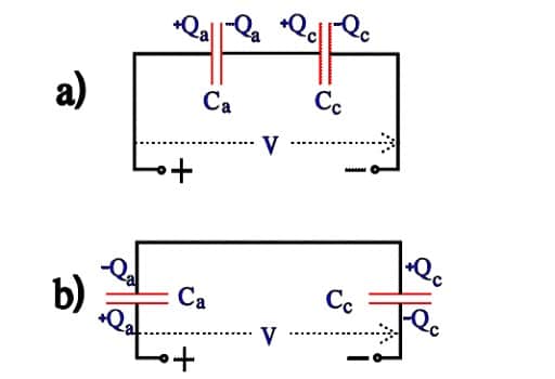
When the external terminals are rapidly discharged, internal charge can redistribute before the slower leakage paths restore equilibrium. Figures 17 and 18 illustrate this distinction between the previously established DC condition and the immediate discharge condition.
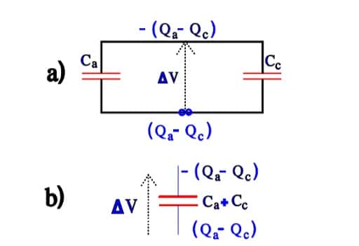
With the charge orientation used in this simplified model, the residual internal voltage magnitude ΔV is expressed by Eq. (7). The expression describes charge sharing between idealised internal elements; it is not an allowable reverse-voltage specification for a complete capacitor.
Repeated stress at the cathode can form additional oxide, reduce cathode capacitance and increase losses. This is a degradation mechanism, not a recommended way to manufacture a bipolar capacitor. The total capacitance then follows the series relationship in Eq. (3), but a damaged polarized device has not acquired the qualification, symmetry or reliability of a purpose-designed non-polar product. [1]
Charge and discharge capability must therefore include peak current, pulse duration, repetition rate, temperature, voltage excursion and circuit resistance. A maximum ripple-current rating alone does not establish repetitive pulse capability. Photo-flash, welding, servo-drive and similar applications may require dedicated constructions and manufacturer approval. [1]
For context, Vishay’s published test summary includes a charge/discharge test for applicable non-solid aluminum types rated up to 160 V: 106 cycles with 0.5 s charging and 0.5 s discharging, using an RC time constant of 0.1 s for each operation. Its stated capacitance-change requirement is ±10%. This controlled qualification test must not be interpreted as approval for unrestricted short-circuit discharge or for every electrolytic series. [7]
Bipolar electrolytics and back-to-back connection
A purpose-designed bipolar aluminum electrolytic has oxide-bearing electrode structures on both sides. It can be represented approximately by two opposing capacitive elements, but the permitted waveform and current remain product-specific. Non-polar construction is useful where voltage polarity may reverse; it does not establish suitability for arbitrary continuous AC power operation. [1]
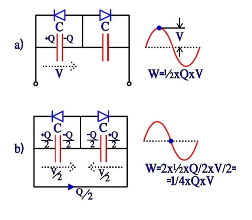
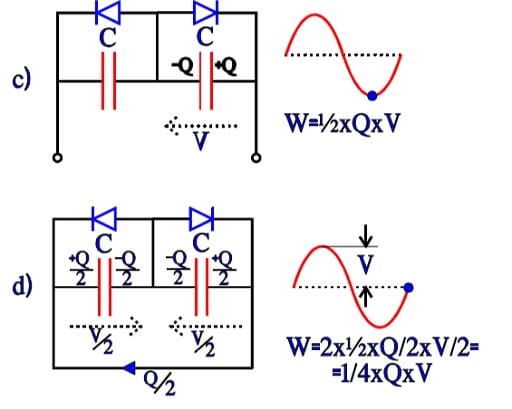
Figures 19 and 20 show the conceptual opposing-element model. For two equal ideal elements, each with capacitance Cel, the terminal series capacitance Ceq is half the element capacitance, as shown in Eq. (8). Cel is an internal element value, not the marked terminal capacitance of a commercial bipolar capacitor.
For terminal voltage V across that ideal combination, the charge magnitude Q and stored energy W are given by Eq. (9). Each equal element supports half the terminal voltage in this ideal, initially balanced model. The total energy is the sum of the two element energies.
The same ideal series relationship applies to DC charging. In a real electrolytic, leakage and electrochemical conduction can change the long-term internal voltage distribution, but they do not justify assigning the single-element capacitance to a bipolar component under DC. Use the manufacturer’s specified terminal capacitance and measurement conditions.
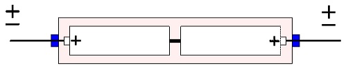
Back-to-back connection of separate polarized capacitors is sometimes used as an approximation to a non-polar component. Historical packaged tantalum arrangements connected two matched units in opposition, as illustrated in Figure 21. Matching does not remove reverse-bias risk: the common-node voltage depends on leakage, initial charge and the applied waveform.
Do not treat an improvised back-to-back tantalum pair as a generally approved AC capacitor. For production equipment, choose a specified bipolar capacitor or an appropriate non-polar dielectric technology, or obtain explicit manufacturer approval for the complete circuit and waveform. Include startup, shutdown and abnormal operating states in that assessment.
Leakage Current and Loss Measurements
Leakage and AC losses describe different aspects of capacitor behaviour. Leakage affects standby consumption and charge retention; ESR and dissipation factor describe AC loss under stated measurement conditions. Neither should be inferred from capacitance alone.
The CV product
The product of rated capacitance CR and rated voltage VR is commonly called the CV product. Eq. (10) defines the corresponding nominal charge quantity QR. If CR is entered in µF and VR in volts, QR is obtained in µC, equivalent to µA·s.
CV is useful when comparing capacitor families and interpreting leakage specifications, but it is not an energy rating. Two capacitors with the same CV can store different energies because energy depends on voltage squared, as in Eq. (9). Rated-voltage CV also does not directly describe the energy available over a restricted operating-voltage window.
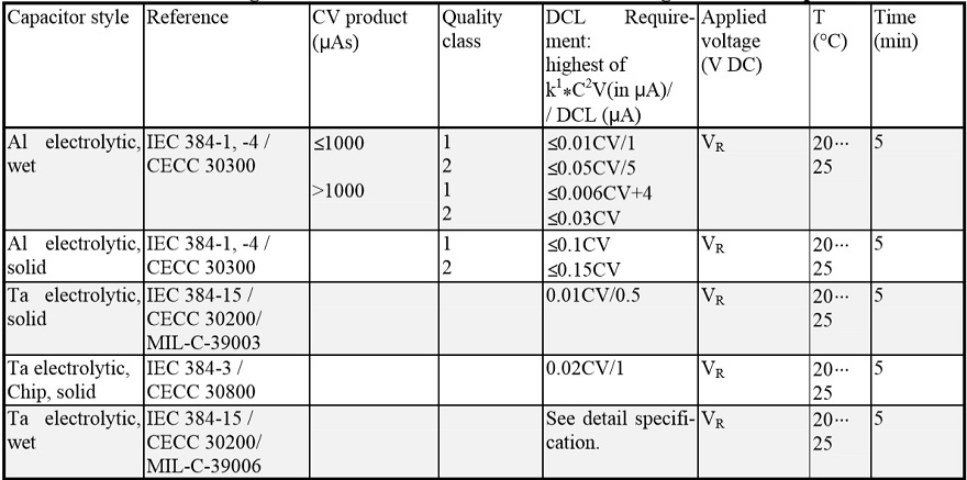
For example, some conventional MnO2 tantalum series specify maximum leakage as the greater of 0.01CV µA and a fixed minimum, with C entered in µF and V in volts. The numerical coefficient is part of that manufacturer’s specified unit convention; it is not a dimensionless material constant. The fixed minimum, test time, temperature and voltage must all be retained when interpreting the limit. [2]
Leakage current and DC leakage
DC leakage, abbreviated DCL, depends on applied voltage, temperature, elapsed time and previous electrical and environmental history. Leakage generally rises with temperature and can rise sharply when the permitted forward voltage is exceeded. The detailed voltage relationship is not universally linear below rating or a single exponential above it. [1, 4]
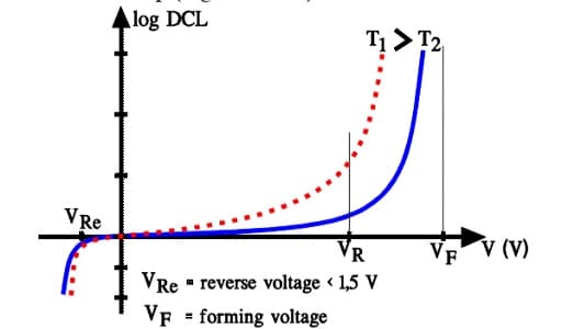
Figure 22 shows the importance of both voltage and temperature. A room-temperature leakage limit should not be used unchanged to calculate high-temperature standby consumption unless the datasheet explicitly permits that interpretation.
Immediately after voltage is applied, measured current includes charging and relaxation components as well as conductive leakage. In wet systems, dielectric reformation can contribute too. Eq. (11) separates these contributions conceptually; imeas is measured current, v is terminal voltage, t is time, irelax is dielectric and interfacial relaxation current, icond is conductive leakage, and ireform is any electrochemical reformation contribution.
Eq. (11) is an explanatory separation rather than a complete fitted model. Once the voltage has stabilised, the ideal charging term tends to zero, but relaxation and reformation may continue. A reading taken immediately after energisation is therefore not directly comparable with a leakage limit specified after a longer electrification time.

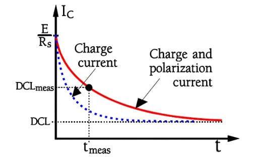
Figures 23 and 24 distinguish initial charging from the slower current tail. Dielectric absorption and interfacial relaxation involve processes with different time constants; a single universal absorption percentage or a fixed time to obtain pure leakage is not appropriate for all electrolytic constructions.
Datasheets commonly specify leakage after a defined period at rated voltage and a reference temperature. The applicable period may be a few minutes, but it must be read from the selected series. KYOCERA AVX’s polymer guide, for example, specifies a five-minute reference and explains why dry components, recently reflowed parts and low-temperature conditions can produce slower stabilisation. [4]
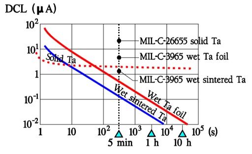
Figure 25 illustrates why test time is part of the specification. Typical leakage may be below the maximum limit, but no fixed typical-to-maximum ratio is guaranteed across production, temperature or life. If the circuit requires a leakage limit tighter than the catalogue maximum, obtain a controlled specification rather than relying on a typical curve.
For low-current measurements, also consider fixture insulation, surface contamination, instrument burden voltage, source stability and discharge history. Measure the actual voltage at the capacitor when a series resistor is used: a leakage-dependent voltage drop can otherwise make the test less severe than intended.
Losses and terminal connections
Losses arise in the electrolyte or solid cathode, dielectric, foils, tabs and connections. In the simplified wet-aluminum model introduced with Figure 12, Eq. (12) combines the loss contributions represented by Rs and Re.
Eq. (12) is a model-level grouping, not a frequency-independent material identity. Each contribution can change with frequency and temperature. At frequencies where the extended network matters, the terminal ESR should be obtained from measurement or a suitable model rather than by adding fixed resistors.

Figure 26 shows why terminal-tab number and position matter. Shorter and better-distributed current paths can reduce foil resistance, while connection geometry also influences inductance and local heating. Equal package dimensions and capacitance do not establish equal internal current capability.
Electrolyte conductivity remains important. Deeper pores can provide more low-frequency capacitance while increasing the resistance of paths to that area. Low-ESR designs balance foil structure, electrolyte conductivity, current collection and package constraints rather than optimising surface area in isolation. [1]
Dissipation factor and ESR
For a series equivalent model at a frequency where inductance and parallel leakage have negligible influence, dissipation factor is related to ESR by Eq. (13). DF is the dimensionless loss tangent tan δ. C and ESR must refer to the same measurement frequency and conditions; a DF quoted as a percentage must first be divided by 100.
A DF limit measured at 120 Hz cannot be inserted into Eq. (13) to predict ESR at 100 kHz. Frequency dependence of both capacitance and loss must be considered. Likewise, impedance magnitude is not identical to ESR except where the reactive contribution is sufficiently small. [1]
Ripple current and self-heating
Ripple current produces internal heat through ESR. For one dominant frequency, the approximate ripple loss is Irms²ESR. For a periodic waveform resolved into frequency components, Eq. (14) sums their contributions. Pripple is average ripple loss in watts; Ik,rms is the RMS current of component k at frequency fk; T is capacitor temperature.
Eq. (14) assumes that the relevant small-signal ESR data adequately represent operation. Large pulses, changing temperature and nonlinear fault conditions require additional assessment. Leakage power is a separate contribution, approximately DC voltage multiplied by leakage current under the operating condition. [4, 6]
The permitted ripple current depends on frequency, ambient temperature and heat dissipation. Apply the selected series’ frequency and temperature correction factors, and assess the actual thermal environment. Nearby hot components, enclosure temperature, board conduction, airflow and mounting can all change capacitor temperature. [1, 4]
Do not add separately specified low-frequency and high-frequency ripple ratings as though they were independent thermal budgets. Where multiple ripple components are present, use the manufacturer’s combined-loading method or obtain application support. Verify the result with the assembled equipment at the relevant worst-case operating states.
Measurements and tests
Capacitance, DF, ESR, impedance and leakage are meaningful only with their measurement conditions. Record frequency, temperature, AC test amplitude, DC bias, electrification time, equivalent-circuit setting and any preconditioning. A production acceptance limit should reproduce the conditions of the applicable specification.
IEC 60384-4:2016 covers fixed aluminum electrolytic capacitors with solid MnO2 and non-solid electrolyte, primarily for DC applications in electronic equipment. Its scope should not be extended automatically to every conductive polymer or special-purpose construction. The applicable sectional specification, detail specification and manufacturer requirements must be identified for the actual part. [8]
Vishay’s aluminum-capacitor test summary specifies the electrical measurement sequence as leakage current, capacitance, tan δ or ESR, and impedance. It also distinguishes endurance, surge, reverse-voltage, storage and charge/discharge tests. Those tests have different purposes and conditions. [7]
Capacitance and dissipation-factor measurement
Use the datasheet reference frequency and temperature rather than selecting whichever instrument setting gives the preferred reading. Nichicon’s general description identifies 120 Hz and 20 °C as reference conditions for the aluminum electrolytics discussed there. Different technologies and specifications may use different conditions. [1]
Use the specified AC test level and any required DC bias so that the measurement does not impose an inappropriate reverse excursion. A series-equivalent capacitance setting is commonly suitable for large, low-impedance capacitors, but the specified method takes precedence. For low ESR, fixture compensation and an appropriate four-terminal measurement arrangement reduce errors from contacts and leads.

Leakage-current measurement
Apply the specified forward voltage through the prescribed source impedance or current-limiting arrangement, and begin timing according to the test method. Measure at the stated temperature after the stated electrification period. A short production test needs a separately validated limit; it is not equivalent to the longer datasheet test merely because the voltage is the same. [1, 4]
Surge-voltage tests
A surge-voltage qualification test applies a defined intermittent overvoltage through a specified circuit for a stated duration, temperature and number of cycles. It is different from a high-current surge test and does not establish a repetitive operating-voltage allowance. [4, 7]
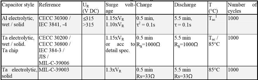
Compare the circuit’s actual overshoot, source impedance and repetition rate with the manufacturer’s guidance. An overshoot within a catalogue surge-voltage number can still be unacceptable if the waveform, temperature or available current differs from the qualification test.
Reverse-voltage tests
A reverse-voltage test evaluates behaviour under a particular controlled exposure. It is not permission to reverse a polarized capacitor during normal service. For example, Vishay’s test summary includes a defined reverse-voltage exposure followed by forward-voltage operation for applicable non-solid aluminum types; that procedure must not be converted into a general operating recommendation. [7]
For a circuit that can reverse polarity, use an appropriate non-polar component or prevent the reversal. Check stored charge in adjacent rails, inductive ringing, supply sequencing and shutdown as well as the normal steady-state waveform.
Design and Selection Checklist
Select an electrolytic capacitor against a defined electrical, thermal, mechanical and environmental requirement. A replacement with the same capacitance and voltage marking is not necessarily equivalent, particularly in switching power supplies, repetitive pulse circuits and long-life equipment.
Choose the construction for the application
Table 4 summarises useful starting points rather than guaranteed technology rankings. Compare actual parts at the required voltage, temperature, frequency and service life; each family contains products with different priorities. [1, 2, 4, 5, 6]
| Construction | Typical reason to consider it | Principal checks |
|---|---|---|
| Wet aluminum | Bulk capacitance, filtering and energy storage across a broad range of packages and ratings. | Ripple heating, low-temperature impedance, endurance, sealing, storage and pulse capability. |
| MnO2 tantalum | Compact capacitance with stable electrical characteristics and established product qualifications. | Voltage derating, startup surge, source impedance, fault energy and temperature limits. |
| Conductive polymer aluminum or tantalum | Low ESR and high-frequency filtering in space-constrained power electronics. | Leakage, temperature and voltage derating, humidity, reflow, surge current and regulator compatibility. |
| Hybrid aluminum | Low ESR and high ripple capability combined with liquid-electrolyte insulation repair. | Series-specific lifetime model, ripple correction factors, thermal environment and assembly limits. |
| Wet tantalum | Compact energy storage and filtering where the selected cathode, package and qualification match demanding requirements. | Cathode construction, category voltage, reverse restrictions, ESR, pulse performance, seals and procurement specification. |
Electrical requirements
- Capacitance: check tolerance and usable capacitance at temperature, frequency and end of life, not only the nominal room-temperature value.
- Voltage: include DC bias, ripple peaks, startup overshoot, load transients and shutdown. Apply the selected technology’s recommended derating and temperature-dependent limits.
- Losses: compare ESR and impedance at the relevant frequencies and temperatures. Do not substitute a 100 kHz impedance limit for a guaranteed ESR limit without justification.
- Ripple and pulses: evaluate RMS current, harmonic content, peak current, repetition rate and self-heating. Confirm repetitive charge/discharge capability separately.
- Leakage: use maximum specified DCL and its operating-temperature dependence for standby-current and hold-up budgets. Include post-assembly stabilisation where relevant.
- Inductance and layout: assess terminal and interconnect inductance where fast edges or high-frequency current sharing matter.
In a switching regulator, the output capacitor is part of the control system as well as the ripple filter. Check the regulator’s permitted capacitance and ESR range before replacing a wet capacitor with a much lower-ESR polymer or hybrid part. Lower ESR can reduce ripple loss while changing damping, the output-network response and the compensation requirement.
For power-input capacitors, evaluate hot-plug and startup current from the actual source, wiring and protection circuit. For signal coupling or timing, leakage, voltage polarity and low-frequency behaviour may matter more than a high ripple-current rating. The best component for a bulk SMPS node is not automatically the best choice for a low-current analogue node.
Startup, pulse discharge and usable energy
For an approximately constant capacitance, charging current follows Eq. (15), where i is current and v is capacitor voltage. A controlled voltage ramp can limit capacitive charging current, but the real startup circuit must also account for source impedance, current limiting and any overshoot.
Low ESR reduces normal ripple loss but can increase the peak current available during rapid charging or a short circuit. Consider current limiting, precharge, hot-swap control or other protection appropriate to the energy and failure consequences. Follow the manufacturer’s surge guidance, particularly for tantalum capacitors on low-impedance power rails. [1, 4]
For a hold-up application, the ideal energy released as voltage falls from Vhigh to Vlow is given by Eq. (16). ΔW is available ideal energy in joules. Use effective capacitance under the relevant conditions and then allow for capacitor losses, converter efficiency, load behaviour and the converter’s minimum input voltage.
A large CV value alone cannot establish the hold-up time. ESR can produce an immediate terminal-voltage drop under load, while ageing and low-temperature capacitance changes can reduce the usable energy margin.
Lifetime, temperature and environment
An endurance rating states a test duration, electrical load, temperature and allowable parameter changes. It is not a guarantee that every capacitor fails at that hour count, nor is it a direct prediction of equipment field life. Use the manufacturer’s applicable lifetime model and its stated extrapolation limits.
For wet aluminum and hybrid constructions, assess both ambient heating and ripple-generated internal heating. For conductive polymer, account for the specified temperature, humidity and package protection; the absence of conventional liquid dry-out does not remove all parametric ageing. Do not apply a wet-aluminum lifetime multiplier indiscriminately to solid tantalum, polymer or hybrid parts. [1, 4]
Check the equipment’s thermal mission profile, including standby, intermittent high load and restricted airflow. A temperature measured on the can or package is not automatically the internal hot-spot temperature; use the manufacturer’s relationship or calculation method where internal temperature is required.
Environmental assessment should include humidity, condensation, corrosive gases, vibration, shock and mounting stress. Check soldering profile, cleaning agents, adhesives and conformal coatings for compatibility. Conformal coating is not automatically beneficial if the material or curing process attacks the seal or encapsulation. [1, 4]
Series and parallel banks
For capacitors connected in series, capacitance tolerance and leakage affect voltage sharing. A balancing network may be required, and its dissipation and leakage margin must be assessed. Check transient sharing as well as the final DC condition, and consider the effect of one capacitor becoming open or shorted. [1]
For parallel banks, capacitances add but ripple current does not necessarily divide equally. Differences in ESR, inductance, temperature and interconnect geometry can concentrate current in particular parts. Mixed wet and polymer banks require particular attention because their impedances and temperature dependence can differ substantially. [1]
A parallel bank also increases the energy that can feed a failed component. Validate the fault response and any individual branch protection rather than considering only normal RMS current sharing.
Catalogue parts, custom parts and qualification
Begin with a standard catalogue series whose guaranteed limits and qualification match the requirement. If the design needs a special terminal arrangement, enclosure, pulse capability, leakage limit, screening flow or environmental rating, obtain a controlled custom specification rather than extrapolating from a nearby catalogue part.
- Confirm the exact ordering code, case dimensions, terminal geometry, polarity marking, mounting method and vent clearance.
- Identify guaranteed limits separately from typical curves, simulation models and portfolio-wide maximum ratings.
- Confirm the qualification and screening applicable to the actual series and ordering code. Automotive qualification, established reliability and hermetic construction describe different attributes.
- For supplier substitution, compare measurement conditions, end-of-life limits, ripple correction factors, surge guidance, humidity performance and assembly restrictions as well as nominal ratings.
- For custom or safety-critical procurement, document acceptance tests, traceability, change notification, storage conditions and application approval.
Safety and discharge
Electrolytic capacitors can fail open, short, leak electrolyte or vent hot gas. Keep pressure-relief paths clear and do not rely on the decorative sleeve as certified electrical insulation. The case potential and permitted mounting arrangement must be checked from the manufacturer’s information. [1]
Before servicing, isolate the energy source, discharge through a suitable rated path and verify the terminal voltage with an appropriate instrument. Do not use an uncontrolled terminal short as the discharge method. Account for dielectric-absorption voltage recovery and for recharge from connected circuitry. [1]
For an ideal capacitor discharging only through resistance Rd, Eq. (17) gives terminal voltage v(t) and the time t required to fall from initial voltage V0 to a chosen threshold Vsafe. The equation assumes constant capacitance, no recharge path and no significant dielectric-absorption recovery.
Choose the discharge path for its initial power, pulse energy, working voltage and failure behaviour, not resistance alone. The applicable equipment safety requirements determine the acceptable voltage threshold, discharge time and required safeguards. A general electrolytic capacitor rating is not an X- or Y-class safety approval for connection across mains or across an insulation barrier.
Conclusion
Electrolytic capacitors obtain high capacitance density by combining a large effective anode area with a thin oxide dielectric. The electrolyte and cathode connection make that area electrically accessible, but also introduce the resistance, temperature dependence and fault-response characteristics that distinguish one construction from another.
Reliable selection therefore requires more than capacitance and rated voltage. Match the complete voltage waveform, ripple spectrum, thermal environment, leakage budget, lifetime requirement and assembly process to the selected series. Treat surge, reverse-voltage and charge/discharge qualifications as defined tests, not general operating permissions, and validate critical behaviour in the finished circuit.
FAQ
These answers summarise the construction and selection principles discussed above. The individual component specification remains the authority for operating limits and measurement conditions.
An electrolytic capacitor uses a thin oxide dielectric on a large-area anode and an electrolyte that contacts the oxide surface. Aluminum, tantalum and niobium-based constructions use different oxide systems. The electrolyte is the conductive counter-electrode medium, not the principal dielectric. Most electrolytics are polarized, although purpose-designed bipolar aluminum types are available.
Wet electrolytics use a liquid electrolyte, conductive polymer types use a solid polymer counter-electrode, and hybrid aluminum capacitors combine polymer with liquid electrolyte. Polymer can provide low ESR, while the liquid in a hybrid supports insulation repair. Compare actual series for leakage, ripple current, temperature, humidity, lifetime and assembly requirements rather than assuming that one construction is always superior.
There is no universal derating percentage for all electrolytic capacitors. Use the selected series’ recommendations and temperature-dependent voltage limits. Include DC bias, ripple peaks, startup overshoot and other transients in the assessment. Tantalum manganese dioxide, tantalum polymer, wet tantalum and aluminum constructions can require different margins. A surge-voltage test rating is not extra continuous operating headroom.
Ordinary polarized electrolytics should not be designed to operate with reverse voltage. Any permitted reverse transient is specific to the part, temperature, duration and waveform. Purpose-designed bipolar capacitors can accommodate specified polarity reversals, but this does not automatically qualify them for continuous AC power service. Check the actual application approval and current limits.
Ripple current produces heat through ESR, so capacitance and voltage rating alone do not establish suitability. ESR changes with frequency and temperature, particularly in wet electrolytics. Compare the ripple spectrum with the manufacturer’s corrected current limits and assess the thermal environment. In switching regulators, also check the permitted output-capacitor ESR range before substituting a lower-ESR part.
Measure leakage at the voltage, temperature and electrification time stated in the selected datasheet. Initial charging and relaxation current can exceed the later leakage reading, and storage or reflow history can affect stabilisation. For stored wet electrolytics, follow the manufacturer’s voltage-treatment guidance where applicable. Reformation does not restore lost electrolyte or repair mechanical damage.
How to Select and Validate an Electrolytic Capacitor
Use this procedure to turn circuit requirements into a controlled component specification. It applies to selection and validation, not to repair or reformation of an unknown capacitor.
Select and validate an electrolytic capacitor against the complete application requirement.
- Define the electrical and thermal requirements
Record the required capacitance, voltage waveform, ripple spectrum, peak charging current, leakage budget, ambient temperature and service-life target. Include startup, shutdown and fault conditions.
- Choose a construction and candidate series
Compare wet aluminum, manganese dioxide tantalum, conductive polymer, hybrid aluminum or wet tantalum against the application. Check guaranteed limits and use the manufacturer’s technology-specific voltage and temperature guidance.
- Check losses, pulses and circuit compatibility
Evaluate ESR and impedance at the relevant frequencies and temperatures. Apply ripple-current correction factors, confirm repetitive pulse capability and check regulator stability, inrush control and any series or parallel bank behaviour.
- Confirm lifetime, assembly and qualification
Use the selected series’ lifetime method and environmental limits. Verify polarity, mounting, vent clearance, soldering profile, moisture handling and applicable qualification. Document any custom requirements and approved substitutes.
- Validate the assembled equipment
Measure capacitor voltage, ripple current and temperature in the relevant operating states. Test leakage and other acceptance parameters under the specified conditions, verify safe discharge and record the final approved part and limits.
Further Reading
These related Knowledge Blog articles provide background on capacitor fundamentals, technology comparisons, capacitance calculations and loss terminology.
- Capacitor, What is it? — An introduction to charge storage, capacitor construction and common circuit functions.
- Capacitor Technologies Overview — Context for comparing electrolytics with ceramic, film and other capacitor technologies.
- Capacitance and its Calculation — Background on permittivity, geometry, capacitive reactance and series or parallel connections.
- Losses in Capacitors: ESR, DF and Q Factor — Further explanation of equivalent circuits, impedance and loss measurements.
References
The numbered references support the construction, material, operating and test information cited in the text. Product-specific guidance takes precedence over generic descriptions, and undated online documents should be checked against the current ordering-code specification.
- Nichicon Corporation, General Descriptions of Aluminum Electrolytic Capacitors and Application Guidelines, Technical Notes CAT.8101H, Nichicon, undated; accessed 2026.
- Vishay Sprague, Guide for Conformal Coated Tantalum Capacitors, document 40150, Vishay, revision 1 February 2024.
- T. Zedníček, Tantalum Polymer and Niobium Oxide Capacitors, technical paper, AVX; hosted by KYOCERA AVX, undated; accessed 2026.
- S. Zedníček, J. Petržílek, P. Vanšura, M. Weaver and C. Reynolds, Conductive Polymer Capacitors: Basic Guidelines, technical paper, KYOCERA AVX, undated; accessed 2026.
- Panasonic Industry, History of Capacitors and How to Select Them, Part 1, Panasonic Industry, 26 May 2025.
- Mike Mosier, Wet Electrolyte Tantalum Capacitors: An Introduction to the Basics, document 40021, Vishay, revision 6 August 2024.
- Vishay BCcomponents, Aluminum Capacitors: Tests and Requirements, document 28358, Vishay, revision 23 July 2026.
- International Electrotechnical Commission, IEC 60384-4:2016: Fixed Capacitors for Use in Electronic Equipment, Part 4: Sectional Specification, Fixed Aluminium Electrolytic Capacitors with Solid MnO₂ and Non-Solid Electrolyte, fifth edition, IEC, 2016.
- KYOCERA AVX, Conductive Polymer Solid Electrolytic Capacitors, online product-family overview, KYOCERA AVX, undated; accessed 2026.
Latest technical review and revision: 27 October 2026. Construction explanations, operating-limit guidance, measurement practice, selection criteria and references reviewed.