Passive Components Blog
No Result
View All Result
  • Home
  • NewsFilter
    • All
    • Aerospace & Defence
    • Antenna
    • Applications
    • Automotive
    • Capacitors
    • Circuit Protection Devices
    • electro-mechanical news
    • Filters
    • Fuses
    • Inductors
    • Industrial
    • Integrated Passives
    • inter-connect news
    • Market & Supply Chain
    • Market Insights
    • Medical
    • Modelling and Simulation
    • New Materials & Supply
    • New Technologies
    • Non-linear Passives
    • Oscillators
    • Passive Sensors News
    • Resistors
    • RF & Microwave
    • Telecommunication
    • Weekly Digest

    TDK Releases Ultra-small PFC Capacitors

    KYOCERA AVX Releases Novel Mini BME Stacked Ceramic Capacitors

    Vishay Releases Class 1 Leaded High Voltage Ceramic Disc Capacitors

    TDK Releases 140C Compact Vibration Robust Automotive Aluminum Capacitors

    DigiKey Presents Factory Tomorrow Season 5 Video Series

    Samsung MLCCs Lineup for In-Vehicle Infotainment

    source: Samtec

    Best Practices for Cable Management in High-Speed and High-Density Systems

    Würth Elektronik Unveils Compact Common-Mode Data Lines Chokes

    Bourns Releases TCO 240 Watt USB Mini-Breaker

    Trending Tags

    • Ripple Current
    • RF
    • Leakage Current
    • Tantalum vs Ceramic
    • Snubber
    • Low ESR
    • Feedthrough
    • Derating
    • Dielectric Constant
    • New Products
    • Market Reports
  • VideoFilter
    • All
    • Antenna videos
    • Capacitor videos
    • Circuit Protection Video
    • Filter videos
    • Fuse videos
    • Inductor videos
    • Inter-Connect Video
    • Non-linear passives videos
    • Oscillator videos
    • Passive sensors videos
    • Resistor videos

    Ripple Steering in Coupled Inductors: SEPIC Case

    SEPIC Converter with Coupled and Uncoupled Inductors

    Coupled Inductors in SEPIC versus Flyback Converters

    Non-Linear MLCC Class II Capacitor Measurements Challenges

    Percolation Phenomenon and Reliability of Molded Power Inductors in DC/DC converters

    Root Causes and Effects of DC Bias and AC in Ceramic Capacitors

    How to Calculate the Output Capacitor for a Switching Power Supply

    Switched Capacitor Converter Explained

    Understanding Inductor Dot Markings and Their Application in LTspice

    Trending Tags

    • Capacitors explained
    • Inductors explained
    • Resistors explained
    • Filters explained
    • Application Video Guidelines
    • EMC
    • New Products
    • Ripple Current
    • Simulation
    • Tantalum vs Ceramic
  • Knowledge Blog
  • Suppliers
    • Who is Who
  • Events
No Result
View All Result
Passive Components Blog
No Result
View All Result

Correlation between Calculation & Practice for Simple TOP-to-BOTTOM PCB Heat Dissipation

11.8.2025
Reading Time: 3 mins read
A A

This Würth Elektronik webinar aim to show where the difference between calculation and measurement of PCB heat dissipation comes from, even for relatively simple assemblies.

Without time-consuming thermal simulations, demanding heat dissipation of assemblies cannot solve satisfactorily.

RelatedPosts

Würth Elektronik Unveils Compact Common-Mode Data Lines Chokes

SEPIC Converter with Coupled and Uncoupled Inductors

Würth Elektronik Releases Push-Button and Main Switches

But, to what extent can simple thermal requirements on PCBs be determined with basic mathematics?

How well do the results correlate with real measurements?

Correlation Between Calculation and Practice for Simple Top-to-Bottom PCB Heat Dissipation Using TIM

Abstract

This presentation investigates the correlation between theoretical calculations and practical observations in thermal management of PCBs, focusing on simple top-to-bottom heat dissipation using Thermal Interface Materials (TIM). The study utilizes a specially designed demo board to evaluate discrepancies between calculated thermal resistances and actual measured temperatures.

1. Introduction

Effective thermal management is critical in modern electronics due to increased power densities. This paper aims to bridge the gap between thermal calculations and real-world performance, providing insights into the factors contributing to deviations.

2. Experimental Setup

2.1 PCB Design and Components  

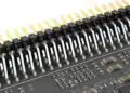
A demo board featuring an SMT component with a D2PAK package mounted on the PCB’s bottom side was designed. The setup included thermal vias, TIM, and a heat sink.

2.2 Measurement Tools  
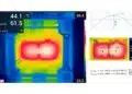
  • FLIR thermal camera
  • Thermocouples for validation
  • Controlled environmental conditions to minimize airflow effects

3. Theoretical Framework

3.1 Thermal Resistance Calculations  

  • Junction-to-ambient (RθJA) and junction-to-case (RθJC) resistances derived from datasheets.
  • Calculation of thermal resistance for vias, TIM, and heat sink using standard formulas.

3.2 Via Array Configuration  

An 11×11 via array optimized for effective thermal conduction, with thermal resistance values computed based on copper conductivity and PCB thickness.

4. Practical Observations

4.1 Temperature Measurements  

Temperatures were measured under various conditions, including different TIM materials, compression forces, and heat sink attachment methods.

4.2 Deviation Analysis  

Observed deviations of up to 20°C between calculated and measured temperatures were systematically analyzed.

5. Discussion

5.1 Sources of Deviation  

  • Inconsistent contact pressure between the heat sink and PCB.
  • Lateral thermal resistance of copper planes.
  • Impact of solder paste thermal resistance.

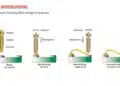
5.2 Mitigation Strategies  

  • Use of screws instead of cable ties for uniform pressure.
  • Optimizing via arrays and PCB copper thickness.
  • Selecting appropriate TIM materials based on application requirements.

6. Conclusion

The study highlights critical factors influencing thermal performance beyond theoretical calculations. Accurate modeling requires considering real-world variables like contact quality, material aging, and PCB design intricacies.

Related

Source: Würth Elektronik

Recent Posts

What Track Width To Use When Routing PCB

6.6.2025
61

IPC Class 2 vs Class 3 Solder Joints Requirements Explained

27.2.2025
501

How to Determine Chip Temperature

3.1.2025
220

Die and Wire PCB Bonding Explained

1.7.2025
157

EMI Shielding Challenges

1.7.2025
15

EMC with Electromechanical Inter-Connections

1.7.2025
15

Designing and Testing HDI PCBs for Harsh Environments

1.7.2025
11

RF PCB Connector Impedance Matching and Dynamics

1.7.2025
54

Basic PCB Technology Overview

1.7.2025
22

How to Process Through-Hole Components by Reflow Assembly

1.7.2025
112

Upcoming Events

Sep 16
17:00 - 18:00 CEST

EMI Shielding Challenges

Sep 22
September 22 @ 13:00 - September 25 @ 15:15 EDT

Pre Cap Visual Inspection per Mil-Std-883 (TM 2017)

Sep 30
September 30 @ 12:00 - October 2 @ 14:00 EDT

MIL-Std-883 TM 2010

Oct 17
12:00 - 14:00 EDT

External Visual Inspection per MIL-STD-883 TM 2009

Oct 20
October 20 - October 23

Digital WE Days 2025 – Virtual Conference

View Calendar

Popular Posts

  • Buck Converter Design and Calculation

    0 shares
    Share 0 Tweet 0
  • Boost Converter Design and Calculation

    0 shares
    Share 0 Tweet 0
  • Flyback Converter Design and Calculation

    0 shares
    Share 0 Tweet 0
  • LLC Resonant Converter Design and Calculation

    0 shares
    Share 0 Tweet 0
  • Dual Active Bridge (DAB) Topology Explained

    0 shares
    Share 0 Tweet 0
  • Ripple Current and its Effects on the Performance of Capacitors

    3 shares
    Share 3 Tweet 0
  • What is a Dielectric Constant and DF of Plastic Materials?

    4 shares
    Share 4 Tweet 0
  • SEPIC Converter Design and Calculation

    0 shares
    Share 0 Tweet 0
  • How to Design an Inductor

    0 shares
    Share 0 Tweet 0
  • Core Materials, Permeability and Their Losses

    0 shares
    Share 0 Tweet 0

Newsletter Subscription


Passive Components Blog

© EPCI - Leading Passive Components Educational and Information Site

  • Home
  • Privacy Policy
  • EPCI Membership & Advertisement
  • About

No Result
View All Result
  • Home
  • Knowledge Blog
  • Premium Suppliers

© EPCI - Leading Passive Components Educational and Information Site

This website uses cookies. By continuing to use this website you are giving consent to cookies being used. Visit our Privacy and Cookie Policy.
Go to mobile version