Passive Components Blog
No Result
View All Result
  • Home
  • NewsFilter
    • All
    • Aerospace & Defence
    • Antenna
    • Applications
    • Automotive
    • Capacitors
    • Circuit Protection Devices
    • electro-mechanical news
    • Filters
    • Fuses
    • Inductors
    • Industrial
    • Integrated Passives
    • inter-connect news
    • Market & Supply Chain
    • Market Insights
    • Medical
    • Modelling and Simulation
    • New Materials & Supply
    • New Technologies
    • Non-linear Passives
    • Oscillators
    • Passive Sensors News
    • Resistors
    • RF & Microwave
    • Telecommunication
    • Weekly Digest

    TDK Extends SMT Gate Drive Transformers to 1000 V

    Non-Linear MLCC Class II Capacitor Measurements Challenges

    Researchers Demonstrated HfO Anti-Ferroelectric Flexible Capacitors

    Connector Industry Achieves Double-Digit Growth

    Stackpole Unveils Metal Element High Current Chip Jumpers

    Common Mistakes in Flyback Transformer Specs

    Vishay Releases Miniature SMD Trimmers for Harsh Environments

    Würth Elektronik Releases Push-Button and Main Switches

    Littelfuse Unveils High-Precision TMR Angle Magnetic Sensors

    Trending Tags

    • Ripple Current
    • RF
    • Leakage Current
    • Tantalum vs Ceramic
    • Snubber
    • Low ESR
    • Feedthrough
    • Derating
    • Dielectric Constant
    • New Products
    • Market Reports
  • VideoFilter
    • All
    • Antenna videos
    • Capacitor videos
    • Circuit Protection Video
    • Filter videos
    • Fuse videos
    • Inductor videos
    • Inter-Connect Video
    • Non-linear passives videos
    • Oscillator videos
    • Passive sensors videos
    • Resistor videos

    Non-Linear MLCC Class II Capacitor Measurements Challenges

    Percolation Phenomenon and Reliability of Molded Power Inductors in DC/DC converters

    Root Causes and Effects of DC Bias and AC in Ceramic Capacitors

    How to Calculate the Output Capacitor for a Switching Power Supply

    Switched Capacitor Converter Explained

    Understanding Inductor Dot Markings and Their Application in LTspice

    Accelerating Full Bridge LLC Resonant Converter Design with Frenetic AI

    Understanding Switched Capacitor Converters

    Coupled Inductors Circuit Model and Examples of its Applications

    Trending Tags

    • Capacitors explained
    • Inductors explained
    • Resistors explained
    • Filters explained
    • Application Video Guidelines
    • EMC
    • New Products
    • Ripple Current
    • Simulation
    • Tantalum vs Ceramic
  • Knowledge Blog
  • Suppliers
    • Who is Who
  • Events
No Result
View All Result
Passive Components Blog
No Result
View All Result

DC-Link Capacitors in Electric Vehicles

3.7.2024
Reading Time: 4 mins read
A A

This article based on Knowles Precision Devices blog discuss function of DC-Link capacitors in electric vehicles.

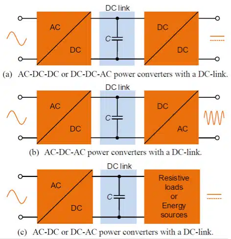
DC link capacitors are commonly used in power converters as an intermediary buffer between an input source to an output load that have different instantaneous power, voltages, and frequencies.

RelatedPosts

Knowles Unveils High-Performance Safety-Certified MLCC Capacitors

Knowles Releases Inductors for Mission-Critical RF Applications

Learn How Supercapacitors Enhance Power System in Knowles eBook

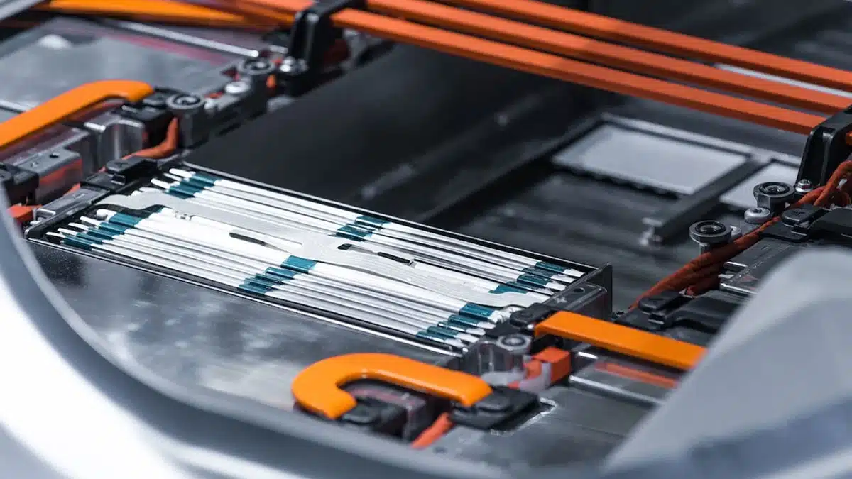
In electric vehicle (EV) applications, DC link capacitors help offset the effects of inductance in inverters, motor controllers, and battery systems.

They also serve as filters that protect EV subsystems from voltage spikes, surges, and electromagnetic interference (EMI).

Figure 1. Common uses for DC link capacitors in power conversion systems (source: Center of Reliable Power Electronics)

Take a look at the on-board charger (OBC) in Figure 2, which is responsible for charging the traction battery. Inside the OBC resides:

  • The AC/DC converter that converts alternating current (AC) from electric grid into direct current (DC) using rectification and Power Factor Correction (PFC)
  • An intermediate DC link circuit for energy buffering
  • The next stage DC/DC converter that adjusts the produced DC voltage to provide correct DC levels to the battery.
Figure 2. Simplified block schematic for AC/DC stage of OBC.

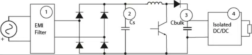
 The DC link capacitor Cbulk is placed between the rectifier and DC/DC converter. Desired characteristics for the capacitor include:

  • High DC voltage rating: 300V to 500V
  • Very large capacitance: 200µF to 1500µF
  • Operating temperature range: -40°C to +250°C
  • Low equivalent series resistance (ESR): < 1.5mΩ
  • High root mean square (RMS) ripple current capacity
  • High mechanical ruggedness

To meet the large capacitance values, multiple capacitors or a capacitor array is required. We recommend using our high-capacitance StackiCap 1812-4040 250V-1.2kV 100nF-5.6µF X7R capacitors for such applications. The DC link capacitor must be also able to handle twice the line frequency. Therefore, common circuit arrangements include multilayer ceramic capacitors (MLCCs) connected in parallel with other capacitor technologies to achieve this. 

Another EV subsystem where DC link capacitors are found is the inverter in motor drive circuits (shown in Figure 3). The inverter converts DC power from the battery to three-phase AC power to drive the traction motors during acceleration, and then converts AC power back to DC during braking. It also detects the motor’s speed and position and drives the insulated-gate bipolar transistor (IGBT) power stages.

Figure 3. Simplified block schematic for inverter in motor driver circuit.

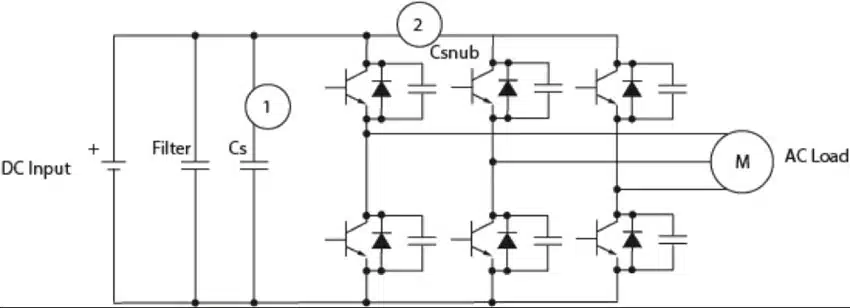
In this subsystem, the DC link or smoothing capacitor Cs is placed in parallel between the DC (battery) and the AC (load) sides of the voltage inverter. The capacitor specifications are very similar to the previous OBC example, and therefore the same StackiCap X7R with high RMS current capacity is recommended. Due to the high capacitance requirements, small-sized MLCCs can be used together with film capacitors and aluminum electrolytic capacitors to integrate closer to the IGBT switching device and improve high frequency attenuation.

Given the high number of converters and inverters found in EV applications, selecting the right high-voltage, high-capacitance DC link capacitor is of great importance to the overall system success. 

Related

Source: Knowles Precision Devices

Recent Posts

Non-Linear MLCC Class II Capacitor Measurements Challenges

19.8.2025
19

Researchers Demonstrated HfO Anti-Ferroelectric Flexible Capacitors

19.8.2025
11

Common Mistakes in Flyback Transformer Specs

15.8.2025
30

Littelfuse Unveils High-Precision TMR Angle Magnetic Sensors

13.8.2025
10

Stackpole Extends Voltage of High Temp Chip Resistors

13.8.2025
11

High Voltage MLCCs Meeting the Growing Demand for Efficiency in Power Conversion

12.8.2025
132

Radiation Tolerance of Tantalum and Ceramic Capacitors

8.8.2025
77

TDK Releases Compact Polypropylene Film Capacitors for Resonant Topologies

7.8.2025
34

Percolation Phenomenon and Reliability of Molded Power Inductors in DC/DC converters

6.8.2025
43

Root Causes and Effects of DC Bias and AC in Ceramic Capacitors

6.8.2025
57

Upcoming Events

Aug 27
17:00 - 18:00 CEST

Capacitor Assemblies for High-Power Circuit Designs

Sep 3
15:30 - 17:30 CEST

How to Choose Your Magnetic Supplier

Sep 16
17:00 - 18:00 CEST

EMI Shielding Challenges

Sep 22
September 22 @ 13:00 - September 25 @ 15:15 EDT

Pre Cap Visual Inspection per Mil-Std-883 (TM 2017)

Sep 30
September 30 @ 12:00 - October 2 @ 14:00 EDT

MIL-Std-883 TM 2010

View Calendar

Popular Posts

  • Buck Converter Design and Calculation

    0 shares
    Share 0 Tweet 0
  • Boost Converter Design and Calculation

    0 shares
    Share 0 Tweet 0
  • Flyback Converter Design and Calculation

    0 shares
    Share 0 Tweet 0
  • LLC Resonant Converter Design and Calculation

    0 shares
    Share 0 Tweet 0
  • What is a Dielectric Constant and DF of Plastic Materials?

    4 shares
    Share 4 Tweet 0
  • Ripple Current and its Effects on the Performance of Capacitors

    3 shares
    Share 3 Tweet 0
  • Dual Active Bridge (DAB) Topology Explained

    0 shares
    Share 0 Tweet 0
  • How to Design an Inductor

    0 shares
    Share 0 Tweet 0
  • Core Materials, Permeability and Their Losses

    0 shares
    Share 0 Tweet 0
  • MLCC Case Sizes Standards Explained

    0 shares
    Share 0 Tweet 0

Newsletter Subscription


Passive Components Blog

© EPCI - Leading Passive Components Educational and Information Site

  • Home
  • Privacy Policy
  • EPCI Membership & Advertisement
  • About

No Result
View All Result
  • Home
  • Knowledge Blog
  • Premium Suppliers

© EPCI - Leading Passive Components Educational and Information Site

This website uses cookies. By continuing to use this website you are giving consent to cookies being used. Visit our Privacy and Cookie Policy.
Go to mobile version