Passive Components Blog
No Result
View All Result
  • Home
  • NewsFilter
    • All
    • Aerospace & Defence
    • Antenna
    • Applications
    • Automotive
    • Capacitors
    • Circuit Protection Devices
    • electro-mechanical news
    • Filters
    • Fuses
    • Inductors
    • Industrial
    • Integrated Passives
    • inter-connect news
    • Market & Supply Chain
    • Market Insights
    • Medical
    • Modelling and Simulation
    • New Materials & Supply
    • New Technologies
    • Non-linear Passives
    • Oscillators
    • Passive Sensors News
    • Resistors
    • RF & Microwave
    • Telecommunication
    • Weekly Digest

    YAGEO Offers High-Performance Diplexers for Dual-Band Wi-Fi 6E/7Integration

    European Components Distribution (DMASS) Faces Continued Decline in Q2 2025

    TDK Announced Wide Frequency Automotive Wirewound POC Inductors

    Bourns Released Rugged, High-Power TO-247 Thick Film Resistor

    Bourns Announced Shielded Power Inductor with High Saturation and Low Radiation

    Würth Elektronik Expands MagI³C with Variable Step-Down Modules

    KYOCERA AVX Releases 600MHz Band71 Compact SAW Duplexer

    binder Supports Miniaturization of Power Supplies with M12 Compact Connectors

    Switched Capacitor Converter Explained

    Trending Tags

    • Ripple Current
    • RF
    • Leakage Current
    • Tantalum vs Ceramic
    • Snubber
    • Low ESR
    • Feedthrough
    • Derating
    • Dielectric Constant
    • New Products
    • Market Reports
  • VideoFilter
    • All
    • Antenna videos
    • Capacitor videos
    • Circuit Protection Video
    • Filter videos
    • Fuse videos
    • Inductor videos
    • Inter-Connect Video
    • Non-linear passives videos
    • Oscillator videos
    • Passive sensors videos
    • Resistor videos

    Switched Capacitor Converter Explained

    Understanding Inductor Dot Markings and Their Application in LTspice

    Accelerating Full Bridge LLC Resonant Converter Design with Frenetic AI

    Understanding Switched Capacitor Converters

    Coupled Inductors Circuit Model and Examples of its Applications

    Inductor Resonances and its Impact to EMI

    Highly Reliable Flex Rigid PCBs, Würth Elektronik Webinar

    Causes of Oscillations in Flyback Converters

    How to design a 60W Flyback Transformer

    Trending Tags

    • Capacitors explained
    • Inductors explained
    • Resistors explained
    • Filters explained
    • Application Video Guidelines
    • EMC
    • New Products
    • Ripple Current
    • Simulation
    • Tantalum vs Ceramic
  • Knowledge Blog
  • Suppliers
    • Who is Who
  • Events
No Result
View All Result
Passive Components Blog
No Result
View All Result

Electricity 101

23.8.2018
Reading Time: 4 mins read
A A
Electric lighting effect, abstract techno backgrounds for your design

Electric lighting effect, abstract techno backgrounds for your design

Source: Kemet Engineering Center article

by Nick Stephen. What’s scarier than your phone is at 1% battery? When your phone doesn’t start charging after you run for your life to get to a power outlet. Maybe it’s your phone charger or maybe it’s the outlet itself. Have you ever wondered how your devices work once they are plugged in? If the answer is yes then you’re in for a treat, welcome to Electricity 101.

RelatedPosts

YAGEO Offers High-Performance Diplexers for Dual-Band Wi-Fi 6E/7Integration

European Components Distribution (DMASS) Faces Continued Decline in Q2 2025

TDK Announced Wide Frequency Automotive Wirewound POC Inductors

Before we get started let’s talk about the electrical grid. The electric grid is the network through which the power is generated, transmitted, and distributed to consumers. The electrical grid is comprised of 4 components; generating plants, transmission lines, substations, and distribution lines. The electricity is initially produced at generation plants. Transmission lines are the infrastructures created to transport electricity over long distances. The electricity voltage is decreased or increased at a substation using the help of transformers. Lower voltage of electricity is transported to different consumers through the distribution lines.

Generation, transmission, consumptionFigure 1: Generation, Transmission & Consumption

3 Phase Power

Power is generated and distributed in three phase (3-phase). Before we get into 3-phase, it would be beneficial to know about single phase. If you’re not electrically minded, think about single phase power like riding a bicycle where only one leg (phase) is pushing on one pedal. Clearly, it is not the best way to ride a bike. Single phase is used every day by people because it is the most common household power circuit and powers their lights, TV, etc. Typically there’s one neutral wire, and power flows between the power wire (through the load) and the neutral wire.

What is 3-phase power? 3-phase consists of three AC voltages separated from each other by 120 electrical degrees and most commercial buildings are wired with 3-phase. Another way to look at 3-phase power is as a combination of three single-phase circuits that deliver power in a way that it never falls to zero, the load will always be same at any instant. If we only had a single phase, then there would be instances where the load is not the same at every point. Why not 6-phase, 9- phase, 12- phase or some other number of phases? For most applications, anything more than 3-phase is unnecessary. More phases do not always mean better. Think about how a tripod for your camera has a clear advantage over a monopod. A 6 legged or 9 legged devices to hold your camera is not going to make a difference because a tripod is already “ideal”.

There are two types of circuits used to maintain equal load across the three hot wires in a 3-phase system- Delta and Wye. The delta configuration has the 3-phase connected like a triangle, whereas the wye configuration has all three loads connected at a single neutral point. Delta is mainly used for any large motors or heaters that do not need a neutral. Delta is also used in power transmission because it is expensive to run a fourth neutral wire all those miles. That’s why distribution transformers are wired as Delta- Wye. This creates the neutral that allows the transformer to deliver power for single-phase loads.

WYE, DELTA, 3-phase

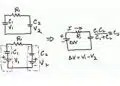
Figure 2: 3-Phase Wye & 3-Phase Delta

Electrical Grid

So how exactly does the grid work? After electricity is generated through the whole 3 phase we talked about, the voltage is stepped up at a substation, allowing electricity to be transported over long distances. In case you were wondering the electricity is still AC at this point, and no, AC is not air conditioning! AC stands for alternating current. Alternating current is better than direct current for transmission because it minimizes power loss. You want to lose as little power as possible in your transmission lines. The stepped-up electricity is then transported to different destinations with the help of transmission lines. Transmission lines can be either overhead or underground. Once it reaches its destination, another substation steps down the voltage to a level suitable for distribution lines that deliver electricity to consumers.

Generation, transmission, distribution

Figure 3: Distribution

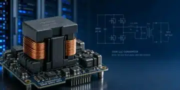
The substations step down voltages based on the consumer requirements. If you refer to the picture above, we can see that our homes are provided with 120V and 240V. The electronics you plug into the wall have other devices inside to step down the voltage even more to meet the requirements. For example, a full wave rectifier shown below has an input of 230V AC and an output of 5V DC (this is an example of what happens inside your phone charger). During distribution of power, capacitors are used for power factor correction (PFC).

AC to DC converterFigure 4: AC to DC Converter

DC links in AC grids

Dc technology provides a more secure and optimized control of a network’s load flow. It also provides quick power restoration in the event of a blackout. An increasing number of DC transmissions embedded in the AC grid will result in a more controllable and precise power exchange. DC technology can provide a more secure and optimized control of the networks load flow. DC transmissions can compensate for fluctuations in power, voltage, and frequency, making it an ideal technology for stabilizing a power system. More DC links will contribute to reduced system losses, increased transmission capacity and improved power quality. DC links often come in form of capacitors. In electricity, DC links capacitors are either film or ceramic.


Related

Recent Posts

Switched Capacitor Converter Explained

28.7.2025
8

Researchers Demonstrated 200C Polymer Film Dielectric

28.7.2025
10

Researchers Demonstrated Zinc-Ion Based Photo-Supercapacitor

28.7.2025
9
Comparative display of a grain size and domain structure; b free energy; c P-E loops after high-entropy ceramics (HECs) and PGS design. source: Nature Communications  ISSN 2041-1723

Researchers Propose Novel MLCC Dielectric Design to Increase Energy Storage Capacity

24.7.2025
37

Understanding Inductor Dot Markings and Their Application in LTspice

21.7.2025
40

Würth Elektronik Present Efficient Motor Controller Evaluation Kit

8.7.2025
37

Advancements and Applications of Switch Capacitor Power Converters

25.6.2025
45

Accelerating Full Bridge LLC Resonant Converter Design with Frenetic AI

24.6.2025
62

Samsung Delivers Silicon Capacitors to Marwell AI Systems

24.6.2025
103

Smoltek CNF-MIM Capacitor Commercialization Update

11.6.2025
47

Upcoming Events

Sep 22
September 22 @ 13:00 - September 25 @ 15:15 EDT

Pre Cap Visual Inspection per Mil-Std-883 (TM 2017)

Sep 30
September 30 @ 12:00 - October 2 @ 14:00 EDT

MIL-Std-883 TM 2010

Oct 17
12:00 - 14:00 EDT

External Visual Inspection per MIL-STD-883 TM 2009

Oct 21
October 21 @ 12:00 - October 23 @ 14:15 EDT

Space and Military Standards for Hybrids and RF Microwave Modules

Nov 4
November 4 @ 12:00 - November 6 @ 14:15 EST

Wirebond Materials, Processes, Reliability and Testing

View Calendar

Popular Posts

  • Buck Converter Design and Calculation

    0 shares
    Share 0 Tweet 0
  • Boost Converter Design and Calculation

    0 shares
    Share 0 Tweet 0
  • Flyback Converter Design and Calculation

    0 shares
    Share 0 Tweet 0
  • LLC Resonant Converter Design and Calculation

    0 shares
    Share 0 Tweet 0
  • What is a Dielectric Constant and DF of Plastic Materials?

    4 shares
    Share 4 Tweet 0
  • Dual Active Bridge (DAB) Topology Explained

    0 shares
    Share 0 Tweet 0
  • Ripple Current and its Effects on the Performance of Capacitors

    3 shares
    Share 3 Tweet 0
  • How to Design an Inductor

    0 shares
    Share 0 Tweet 0
  • MLCC Case Sizes Standards Explained

    0 shares
    Share 0 Tweet 0
  • MLCC and Ceramic Capacitors

    0 shares
    Share 0 Tweet 0

Newsletter Subscription


Passive Components Blog

© EPCI - Leading Passive Components Educational and Information Site

  • Home
  • Privacy Policy
  • EPCI Membership & Advertisement
  • About

No Result
View All Result
  • Home
  • Knowledge Blog
  • Premium Suppliers

© EPCI - Leading Passive Components Educational and Information Site

This website uses cookies. By continuing to use this website you are giving consent to cookies being used. Visit our Privacy and Cookie Policy.
Go to mobile version