


“Failure analysis of capacitors and inductors” article by Javaid Qazi and Masahai Ikeda from KEMET Electronics appeared in ASM International® publisher book “Microelectronics Failure Analysis Desk Reference”, Seventh Edition edited by Tejinder Gandhi. Passive components blog received permission from both authors and publisher to share this article on passive-components.eu website.
Failure Analysis of Capacitors and Inductors
Chapter by
Javaid Qazi
KEMET Electronics, Simpsonville, SC USA also, an Adjunct Faculty at the School of Materials Science and Engineering, Clemson University, Clemson, SC
Masahai Ikeda
TOKIN a subsidiary of KEMET Electronics, Sendai, Japan
source: Kemet Engineering Center White Paper
Abstract
General construction of Tantalum, Aluminum electrolytic, Multi-layer Ceramics, Film, and Super capacitors and Common Mode Choke and Surface Mount inductors are explained. Major failure modes and the mechanisms for each one of these are discussed. Different failure analysis approaches used for these components along with development of some of these techniques are described as well.
Introduction
There is an increasing use and reliance on electronics in daily life, from portable electronics to pacemakers, high reliability of these systems is expected and demanded. Passive components might not be the “brains” of these electronic systems, however, failure of any of these could result in a partial to complete electronic system shutdown. These malfunctions lead to annoyance or can escalate to safety or even life-threatening situation. Failure Analysis (FA) of these components helps determine the root cause and improve the overall quality and reliability of the electronic systems.
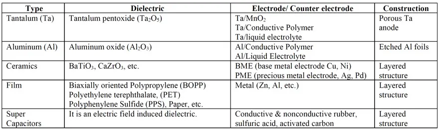
Passive components can be broadly divided into Capacitors (CAPS), Resistors, and Inductors (INDS), with each having drastically different functions and hence constructions. Within each of these categories, there are subcategories, based on different materials and constructions used in each, as listed in Tables 1 and 2 [1]. This makes the FA of passive components a broad topic. The current work supplements an article in the previous edition of Microelectronics Failure Analysis Desk Reference [2]. General construction of select components along with typical failure modes and relevant FA techniques are discussed.
Before delving into the specific FA approaches for different components, some of the common FA practices are briefly discussed here. Examining and documenting the failed component in as-received condition, such as physical anomalies and damage, orientation on the board, condition of the surrounding parts, and so on, are crucial, as these provide invaluable information. Understanding, documenting and in many instances, confirming the reported failure mode (i.e. leakage or short, open circuit, etc.) is the next important step.
Next non-destructive internal and external examinations by optical microscopy, X-ray, C-mode Scanning Acoustic Microscopy (C-SAM) and so on, should be performed. Performing basic electrical characterization, which is discussed in individual sections, is the next logical step. The reader is encouraged to refer to the specific components’ section below to ensure that no further damage occurs to the component due to any of the above analyses. Before performing any FA, it is critical to gather history of the failed component, including lot information, board mounting and washing conditions, any testing performed on it, when and how it failed, what failure was detected and so on. Ensuring that counterfeit or wrong component is not the cause of failure is another consideration. Understanding the construction of the component plays a vital role in performing FA, as it varies within each category, as well as, across manufacturers (some of which are listed in references [1, 3-7]).
The type of failure, component construction and condition determine the best isolation approach. Removal with hot air pencil, cutting the leads or solder pads, cutting the board around the component, etc. are the common options for isolation. The goal is to remove the component with little or no damage.

Proper safety and handling practices, and applicable codes should be followed. Improper handling of chemicals and/or electrical systems could cause bodily injury or even death.
Capacitors
A simple capacitor consists of a dielectric between two conductive materials. One way of having high capacitance in a small volume is to increase the dielectric-electrodes surface area in a given volume, which is done using different types of constructions, as listed in Table 1. Different types of CAPS along with their constructions and failure modes are discussed below.
Tantalum Capacitors
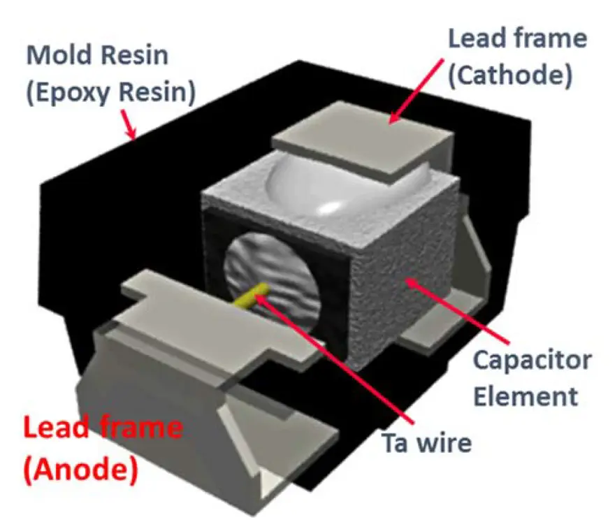
Tantalum CAPS (Ta-CAPS) typically consist of a porous Ta anode (for high surface area) with a Ta wire attached to it. The dielectric, amorphous Ta2O5, typically a few tens of nm thick, is electrochemically grown on all surfaces of the porous Ta anode [1]. Liquid electrolyte, MnO2, or conductive polymer are three commonly used counter electrodes, with the latter becoming the most commonly used. The positive connection is typically created by welding the Ta wire to a Lead Frame (LF).
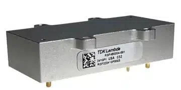
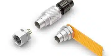
For solid state devices, connection between the counter electrode (polymer or MnO2) and the negative LF is made using conductive pastes and/or solders. Typically, the surface mount devices (SMD) are over molded (Fig. 1) [1]. Whereas, the wet and some through hole devices are typically hermetically sealed in a metallic can or a ceramic container. For wet Ta CAPS, an acid based liquid solution is used as the negative electrode. Other through hole devices are conformally coated or overmolded.
Thanks to their benign failure mode and better electrical performance, conductive polymer Ta-CAPS are commonly used Ta-CAPS and rest of the section is mainly focused on this type, though most of what is discussed, is applicable to other Ta-CAPS as well. Ta-CAPS can fail in high leakage/short, high ESR (Equivalent Series Resistance) or open/low capacitance mode, with high leakage/short being the most common mode.
The high leakage or short failure could happen either as a result of compromised dielectric (Ta-oxide) thereby allowing the positive electrode (Ta metal) to come in direct contact with counter electrode (MnO2, Conductive Polymer or liquid electrolyte). This typically will happen in or on the porous Ta anode. The other possibility is when a leakage path is created which by-passes the dielectric. This can be created either inside the molded device (bridging between positive and negative LFs) or the CAP is completely by-passed as a result of bridging between the negative and positive pads on the circuit board. In case of hermetically sealed Ta, the bridging could occur on the can lid, between the can (negative) and the positive wire.
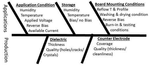
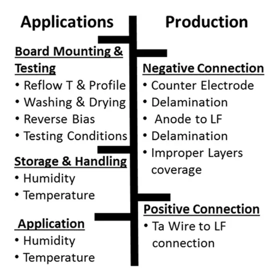
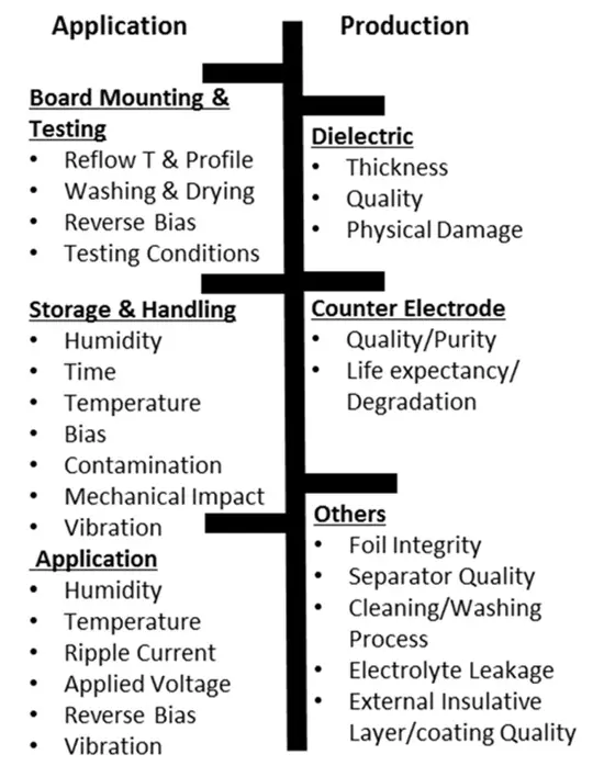
The common causes leading to high leakage or short failure by any of the above-mentioned mechanisms are grouped under production or application of the Ta-CAPS (Fig. 2) [8]. Most of the times failure occurs as a combination of different factors from these two groups.
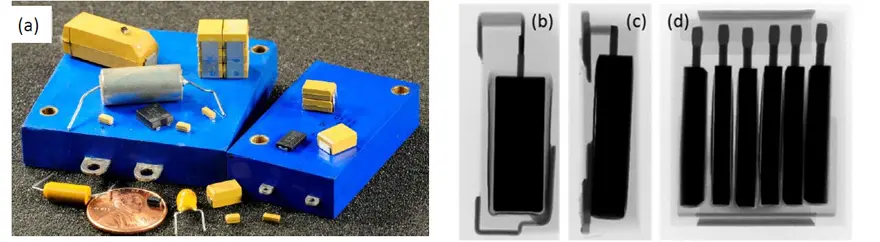
Before starting the actual destructive analysis, it is critical to document, as accurately as possible, the condition and the failure mode of the failed Ta-CAP in its as-received condition. The external and internal constructions of Ta-CAPS could be significantly different from one type of Ta-CAP to another (Fig. 3) and from one supplier to another [1, 3-7]. Consequently, thorough understanding of the Ta-CAP’s construction is essential for a fruitful FA. Needless to say, each manufacturer best understands their components and hence is best equipped for performing FA on them.
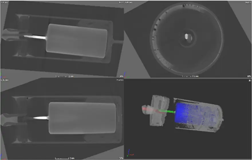
Recent developments in X-ray technology allow better understanding of the internal construction of these Ta-CAPS. One such example is X-ray Computed Tomography (X-ray CT) which allows simultaneous virtual sectioning of a component from different directions. Fig. 4, for example, shows virtual sections of a polymer herm sealed Ta-CAP from different directions, showing Ta anode alignment in the can, as well as, presence of voids in the can-to-lid solder seal.
The next step in FA process is to document the electrical characteristics of the Ta-CAP, such as capacitance, dissipation factor (DF) and ESR. It is note-worthy that DC leakage is purposely omitted here. Ta-CAPS like some other CAPS have self-healing capability. A Ta-CAP with high leakage conditions could heal once DC voltage and current are applied to it. Conversely, application of voltage and current can cause a thermal runaway condition, thereby further destroying the Ta-CAP. Either of these scenarios is not helpful for FA.
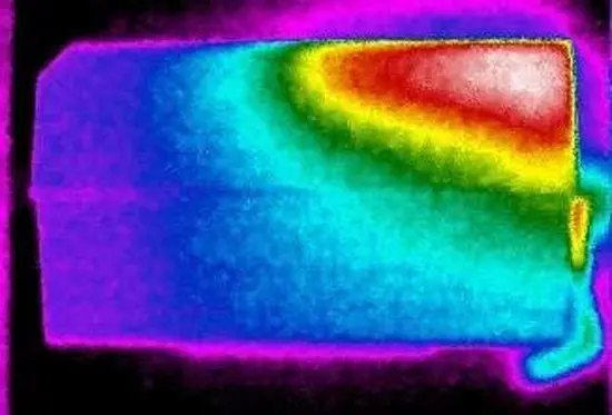
It is therefore recommended to measure DC-resistance (DCR) instead of DC-leakage, which for a good Ta-CAP (depending on the type of CAP) will be in megaohms range. The analyst should be careful to limit the voltage and current the CAP is exposed to during DCR measurements, as it could alter the CAP. In the absence of any external or internal anomalies detected by optical and X-ray examination, thermal imaging could be helpful in determining the location of failure site.
The temperature gradient in a thermal image highlights source of heat. A hot-spot determined from thermal imaging is indicative of localized heating from a failure. Fig. 5 shows a bright red/white hot-spot, highlighting failure site near the negative end of the component. Thermal imaging along with X-ray and optical imaging, help in getting to the fault plane and hence
allowing detailed analysis of the fault site and the surrounding area. This combination is especially helpful, for multiple anodes and stack Ta-CAPS, to determine how many and which anode(s) have high leakage or short condition. Caution should be exercised to limit the current and voltage applied to the Ta-CAP for thermal imaging, as it could cause additional damage.
Voltage applied should not exceed the application or rated voltage, whichever is lower. The current can be limited via the power supply used or by adding a resistor in the circuit. Thermal imaging is a balancing act between limiting the voltage and current exposure and obtaining a thermal hot-spot.
Examination of the fault site might not always allow the determination of the cause of the failure. Different causes of failures (Fig. 2), lead to similar end-result: damaged dielectric, thermal interaction between Ta, dielectric and counter electrode, etc. The thermal and mechanical damage resulting from a failure can destroy evidence as to what caused the failure.
This is where knowing the history and conditions the component was exposed to, be it board mounting, washing, storage, electrical and thermal exposures, etc., becomes very helpful in determining what failure mechanism/s might be at play. For example, most surface mount Ta-CAPS are not hermetically sealed.
Extended exposure of these molded devices to harsh environments, such as high humidity and temperature, could lead to metal corrosion and ionic migration (e.g. Cu, Ag, Sn). This could create bridging on the positive end or compromise healing ability on the negative end. Significant work has been done to reduce/eliminate these ionic migrations [9]. Ionic migration might not look like a typical dendritic structure because it is happening in different layers or interfaces between different materials. Significant moisture pickup can also cause internal counter electrode swelling and/or oxidation resulting in higher ESR.
Moisture pickup by the CAP can also lead to increased capacitance by connecting areas which are not completely covered by solid electrolyte. It is worth mentioning here that some of the Ta-CAPS are classified as Moisture Sensitivity Level 3 (MSL 3) by the manufacturers and should be treated as such. Improper handling could lead to immediate or latent failures. Storage of molded Ta-CAPS in a humid environment can lead to significant moisture pick up, which can result in a “popcorning effect” (swelling and cracking of mold epoxy due to gas pressure buildup) during reflow.
Dielectric quality plays a vital role in determining the leakage current of a CAP. Pin holes, cracks, or any other artifacts in the dielectric could lead to higher leakage or short condition. Crystalline oxide nodules in otherwise amorphous dielectric can create high leakage conditions. Everything else being equal typically 35V and higher rated Ta-CAPS are more prone to this.
Reference [8] is recommended for more details. Over the years, many processes have been developed to minimize/eliminate crystalline oxide growth [10,11], such as preventing or removing contaminants, etc. With the demand for lower and lower ESR, from hundreds to tens and even to single digit milliohms, ESR failures analysis are becoming crucial. Most of these low ESR surface mount Ta-CAPS are conductive polymer-based and are not hermetically sealed, hence they are sensitive to moisture and temperature exposures.
The most common causes for ESR failure are listed in (Fig. 6). Failures could result from one or a combination of these production and/or application causes. ESR failures typically result from a compromised positive or negative connection. Polymer conductivity gets impacted with moisture and/or elevated temperature exposures, especially in harsh environments, which in extreme cases can also lead to ESR failures. Either extremes, too moist or too dry (e.g. vacuum, space) can lead to failure and are active areas of research to improve these. Work has been done to improve the stability of the conductive polymer at elevated temperature and thus keeping lower ESR values [12].
The first step of an ESR FA is to confirm the failure. Measuring the ESR on the board in as-is condition, is necessary. Additionally, one needs to understand the electrical circuit which the CAP is part of, as the measured ESR of the CAP on the board might not accurately reflect the ESR of the component. Detailed external examination of the CAP on the board allows detection of any anomalies (cracks, loose connection, etc.) on the CAP and its surroundings.
Next X-ray analysis in as-is form could provide valuable information for internal construction as well as the solder connections. Once the CAP is electrically isolated by cutting the traces on the board, ESR should be measured again. Removal of the CAP from the board should be done with the least amount of thermal and mechanical stress on the CAP, as either one of these could change the connections.
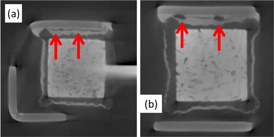
Cutting the board around the CAP, with minimal damage is one of the options. This allows thorough internal construction examination with X-ray analysis and X-ray CT in some cases could be very helpful. De-soldering if necessary, should be done carefully to avoid over heating of the CAP. Fig. 7 shows an example of a negative connection issue which could lead to high ESR. X-ray CT images (Fig. 7) show virtual sectioning of the same CAP from two different directions. Significant delamination and voids (red arrows) between the silvered Taanode and the conductive adhesive used for attaching it to the negative LF can be seen in this case.
Based on the X-ray analysis, the CAP could be prepared for detailed internal examination by sectioning it to a specific plane. Typically, for a single Ta anode CAP, sectioning it parallel to Ta wire to the center of it, exposes all the interfaces. For a CAP with a significantly higher ESR, micro-probing of the sectioned part allows to further isolate the problematic interfaces. Microprobing allows resistance measurements of interfaces in a Ta-CAP.
These measurements are typically taken form: positive LF to Ta wire, negative LF to conductive adhesive (CA), counter electrode layers to CA, etc. This approach allows determination of the interface/s of higher resistance, which will be contributing to the overall ESR. SEM analysis can then provide a closer look at these specific interfaces, to help determine the root cause. Caution must be exercised, both in sectioning as well as micro-probing, because both steps can introduce artifacts. Potting and sectioning should be done in a way to minimize smearing or layer separations which could give misleading results.
Low capacitance and high DF are typically not common issues for Ta-CAPS and interested readers can look up [8] for more details. In case of the wet Ta-CAPS breach in the hermetic seal can result in electrolyte leakage which could cause low CAP and/or high leakage/short issue if it bridges between the positive wire and the can.
Aluminum Electrolytic Capacitors
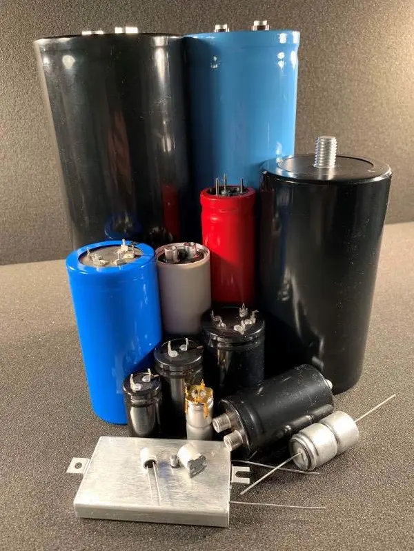
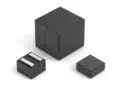
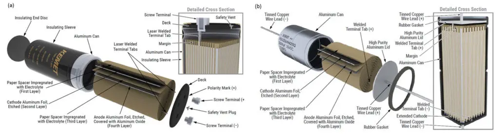
Al-electrolytic CAPS (Al-CAPS), based on their capacitance and rated voltage, are available in a wide range of shapes and sizes. Many of these are custom designed for certain applications, resulting in drastically different constructions, (Fig. 8). Al-CAPS can be broadly divided into two categories: axial and radial. Axial types typically have lead wires on both ends, though there are variants that use crowns for vertical mounting. Some are even surface mountable. Radial types are single ended, i.e., both terminals on same side. The most common ones have screw, snap in, or press-fit terminals. The failure analyst should determine the exact part number and refer to the manufacturer for detailed construction before performing a detailed FA.
A typical Al-CAP consists of a cathode and an anode Al foils wound with a separator (typically paper) between them (referred to as the “wound element”). The wound element is impregnated with liquid electrolyte and/or a conductive polymer, which is then sealed in an Al-can, typically using an Al-lid or an insulative deck (depending on the construction) and a rubber seal.
Al-tabs which are attached to both anode and cathode foils during the winding process, provide electrical connection to the external terminals. Etched anode foil is used to gain significant surface area, hence higher capacitance in the same volume. The dielectric, aluminum oxide, is grown electrochemically over the etched surface before assembling the wound element. Fig. 9 shows examples of the internal construction of two different types of Al-CAPS from a manufacturer. Once the wound element is placed in the Al-can
and sealed (not hermetically), typically an insulative jacket/coating is applied to isolate the Al-can (negative terminal) from the environment. The rubber seal (not hermetically sealed) could allow slow loss of electrolyte eventually resulting in parametric failures.
Leakage of electrolyte because of the poor workmanship (bad seal, vent, etc.), external damage to Al-can, seal or terminals, or exposure to high temperature could also result in similar problem. This can be detected by optical examination followed by any residual analysis if needed, such as Fourier Transform Infra-Red (FTIR) spectroscopy. Bubble testing could be another possibility to check the seal of the can. Significant mechanical impact on the Al-can, could result in foil damage and electrolyte leakage leading to high leakage current.
High mechanical impact and/or vibration can also compromise the internal connections of the foils/Tab/terminals, which cause high leakage/short or open circuit condition. Severe vibration can also result in similar internal or external damage to these CAPS, though it might not be easy to detect the effects of vibration. The failure analyst should examine if the parts were secured properly in their application environment (e.g. clamped, etc.).
High transient voltage can cause breakdown of the Al-oxide dielectric which could result in high leakage or short failure. Application circuit analysis is helpful in cases like these. Al-CAPS can fail in short/catastrophic breakdown, open or low capacitance mode. High leakage or short in these CAPS, like Ta-CAPS, also occurs as a result of dielectric compromise or by-pass of the active CAP. Fig. 10 lists some of the common causes for high leakage or short failure modes of Al-CAPS. The by-pass could occur internally or externally. In both cases, the bridging between positive terminal and negative terminal/Alcan could occur as a result of corrosion or contamination.
The external bridging could occur on the board. Careful external examination of a failure in as-received condition is very critical for determining this. Entrapment of solution between Al-can and the insulative sleeve/coating (washing, condensation) either during manufacturing process or post board mount washing, can later cause the liquid to seep out and cause bridging. Presence of ionic species, typically coming from different components, the boards itself, or the fluxes used, can make this liquid conductive. This can bridge and/or can cause electromigration of conductive species.
Exposure of parts during transit and/or at a customer’s location to chemicals, can result in corrosion of the external terminals resulting in leakage and/or ESR issues. Seepage of some chemicals into the Al-can through the seal (not hermetically sealed), especially chloride containing chemicals can then attack the aluminum oxide and can create leakage condition.
Simple things like fumigants used at international customs, though rare, could sometime create such conditions. In case of fully solid Al-CAPS (conductive polymer only), extended exposure to high temperature and high humidity can allow humidity seepage into the parts, causing high leakage or short condition.
Most of the Al-CAPS are not hermetically sealed. The rubber seal is used along with a vent (in many cases) to allow the CAP to release pressure which could develop over time with the generation of hydrogen because of liquid electrolyte degradation, and/or external heating. High leakage can create internal heating which could result in a similar venting event.
Consequently, the manufacturers of Al-CAPS define an end of life time for these types of CAPS. This is a well-known phenomenon in Al-CAPS and typically results in low or no capacitance (because of electrolyte loss) and/or high ESR. Continued degradation of Al-CAP in this way could lower its output voltage, which with ripple currents can lead to a high leakage or short failure. Therefore, knowing the life history of these types of CAPS is very helpful in FA. Corrosion of external terminals, resulting from the presence of corrosive application/storage environment, could increase the ESR as well. Thorough external examination of the CAP before doing any destructive analysis, will be very helpful in this case as well.
Once a high leakage or short condition is confirmed, internal construction examination of the Al-CAP by X-ray CT could help reveal the fault site. After all the non-destructive analysis is performed, the wound element can be removed from the Alcan and unwound for further analysis. Analysis of leakage/short site by optical and/or SEM-EDS analysis could provide more insight into cause (e.g. contamination, damage, etc.).
Multi Layered Ceramics Capacitors (MLCC)
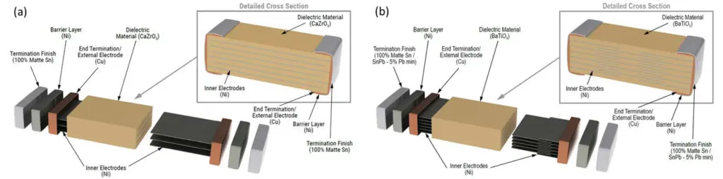
Unlike Ta and Al-electrolytic CAPS, MLCCs are non-polar devices, thus work with electrical bias applied in either direction. The MLCCs are produced by stacking sheets of dielectric (e.g. BaTiO3, CaZrO3, etc.) layers on top of each other with electrode layers in between. The electrode layers are shorter in dimension than the dielectric layers to avoid exposure to the outer-surface except from one side.
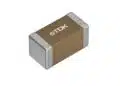
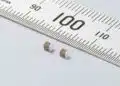
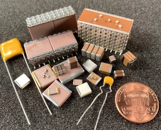
The stacking is done such that every other electrode is displaced to be exposed to one termination side, thus making two adjacent electrodes to be connected to opposite terminals. After firing (high temperature sintering) to attain bonding between different layers, end terminations are applied to make electrical connection with all the electrodes on each side. Two different constructions of MLCCs are shown in (Fig. 11): a regular design where every other electrode is connected to one terminal (Fig. 11a) and higher reliability design which has floating electrodes, not connected to either terminal to provide safer failure mode (Fig. 11b). Apart from internal construction differences, MLCCs are available in variety of different sizes and constructions (Fig. 12).
Low Insulation resistance (IR) or short, along with low or no capacitance are the two most common failure modes for MLCCs. As discussed in an earlier section, internal and external examinations of the failure in as-received condition using nondestructive techniques is invaluable and should be done before proceeding any further.
Low IR or short failures could result from bridging either of the electrodes internally or external bridging across terminals. The former can be caused by cracking (flex or thermal), internal contamination (embedded during production), thinner or inhomogeneous layers’ thickness, or delamination between adjacent layers. Voids in the ceramic dielectric layer resulting from manufacturing process can significantly reduce the effective dielectric thickness locally, which can lead to lower breakdown voltage and low IR/ short conditions. The external bridging could be on the board (between the pads) or on the CAP, resulting from surface contamination (especially conductive species).
The contamination leading to external bridging could come from a variety of sources including production process of MLCC, their storage and handling, board mounting and/or application. The presence of moisture and applied bias with surface contamination can create an ideal environment for electromigration of metals such as Sn, Ag or Cu, which are used in the construction of these MLCC as well as in the solders used for mounting and the printed circuit boards themselves.
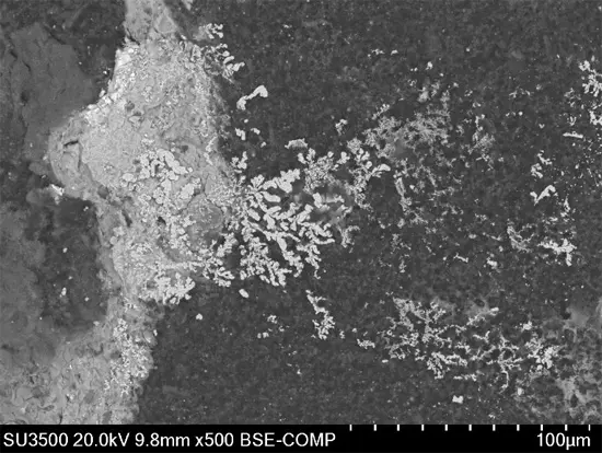
The scanning electron microscopy image in (Fig. 13) shows migration of Ag on the surface of a contaminated MLCC after high temperature and high humidity exposure with voltage applied. For an over molded MLCC, if electromigration is suspected, the epoxy should be removed carefully and both the epoxy and the MLCC surfaces should be examined for evidence of electromigration.
Once the MLCC has been analyzed externally, cleaning the surface and remeasuring IR can help confirm if the issue was caused by external bridging. For multi-chip devices, the problematic chip must be identified and isolated before doing any further analysis. The failure analyst needs to be careful not to introduce artifacts in the process of doing this. If the external bridging is confirmed no further FA is needed.
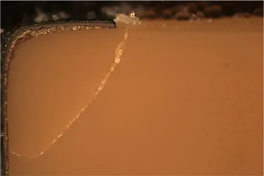
Another cause for low IR or short condition is cracks in the MLCC, especially flex cracking, which can result from stress on the rigid MLCC, during board mounting and/or board handling. Cracking can expose new surfaces of two or more opposing electrodes in close vicinity. Moisture or other conductive material can get to these exposed surfaces and can bridge the two opposing electrode causing low IR or short condition. The presence of moisture and bias could also result in electromigration in these cracks. The heat generated by a failure can further propagate the cracks, thus making it even worse. Flex cracking is one of the most common causes of failure and typically shows a crack from the edge of the termination at the board into the chip (Fig. 14). It is worth pointing out that chips are not always board mounted with the electrodes parallel to the board, especially for the near square chips (similar width and height), thus making detection of flex cracks somewhat tricky.
Typically, the MLCC is sectioned from a side so that both the end terminations and the electrodes layers can be examined. Therefore, the failure analyst should document the CAP orientation on the board before performing any FA. Thorough external optical examination using regular and polarized light could help identify some of these cracks. “Vicinal illumination” can be especially helpful to aid in detection of very tightly spaced cracks and delamination between layers that may be obscured or undetectable with traditional lighting techniques [13].
Depending on the chip size and design, X-ray examination might be able to reveal some of these cracks. Based on optical and X-ray analyses along with MLCC construction, potting the CAP in an epoxy and sectioning it allows much closer look at its internal structure. Apart from the CAP orientation (as discussed above) caution must be exercised not to introduce cracks during sectioning process, as the rigid ceramic body is prone to cracking.
With better understanding of flex cracking, manufacturers of MLCCs have developed flex crack mitigation designs. One such approach is general improvement of flexibility of the component. Now MLCCs that can withstand up to 5mm of flex are available [14]. Another improvement is usage of flex terminations, which tear off from the ceramic body rather than flex cracking it, thus making MLCCs fail as an open circuit (safer failure mode) rather than low IR or short condition [14].
Delamination/ parallel cracks between electrode and dielectric, typically a manufacturing fault, could grow with thermomechanical stress during the application. Consequently, these could jump across different electrode layers and cause cracking of the dielectric layer, thus exposing two opposing electrodes. Formation of a conductive path (as described above) between these opposing electrodes (moisture and/or ionic species) can lead to low IR or short condition.
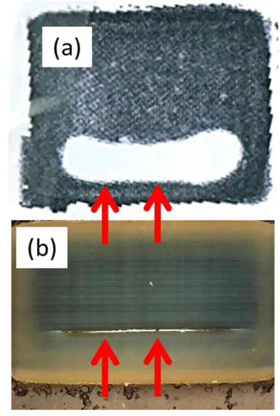
C-mode Scanning Acoustic Microscopy (C-SAM) allows the determination of such delamination. High reliability MLCCs are routinely scanned using C-SAM to inspect for any delamination. Once cracks or delaminations are detected, sectioning the part to the plane of interest could provide more insight into the root cause of the failure.
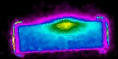
For example, gross delamination detected by C-SAM in a MLCC, (Fig. 15a), helped guide in the sectioning process, which confirmed the delamination (Fig. 15b). In certain cases, thermal imaging could help determine the hot spot location in the CAP. Similar principles apply for thermal imaging as for Ta CAPS. The thermal image in (Fig. 16) shows the presence of a hot spot in a cross-sectioned MLCC, indicating the presence of sub-surface fault site in this case, as no external damage was detected.
Mechanical or physical impact to the MLCC can create cracks which can lead to low IR or short condition. Thermal shock can create cracks inside the MLCC, which can lead to low IR or short condition. Although not common, over voltage is another possible cause for a low IR or short condition. The typical breakdown voltage for MLCC is three times or more of the rated voltage.

Some of the dielectrics used in MLCC have an aging phenomenon associated with their capacitance, i.e. their capacitance drops significantly with time (40-50% or even more). For class 1 dielectric such as C0G, capacitance change, within the typical temperature range of -55°C to +125°C, is very little. Class 2 and 3 dielectrics, on the other hand, have significant temperature dependence. It is a well-known phenomenon among the MLCC manufacturers [15]. The capacitance loss can be regained by a de-aging heat-treatment, typically above 150°C. The failure analyst needs to be aware of this before performing any kind of destructive analysis, as it will not show any problem with the MLCC.
Low or no capacitance can also result from disconnection of some or all electrodes to its termination respectively, thus making electrodes electrically isolated. X-ray CT in some cases might reveal the disconnection between the electrodes and end termination (Fig. 17). After performing the electrical and external examination, cross sectioning of the MLCC to expose electrodes, will allow determination of which electrodes lack connection with the termination.
If it is not readily visible by optical examination, then Cu back-plating (a technique to decorate the active electrodes), thermal imaging, or microprobing can identify the culprit. Once the electrodes in question are identified, SEM could allow deeper understanding on the cause of delamination.
Film Capacitors
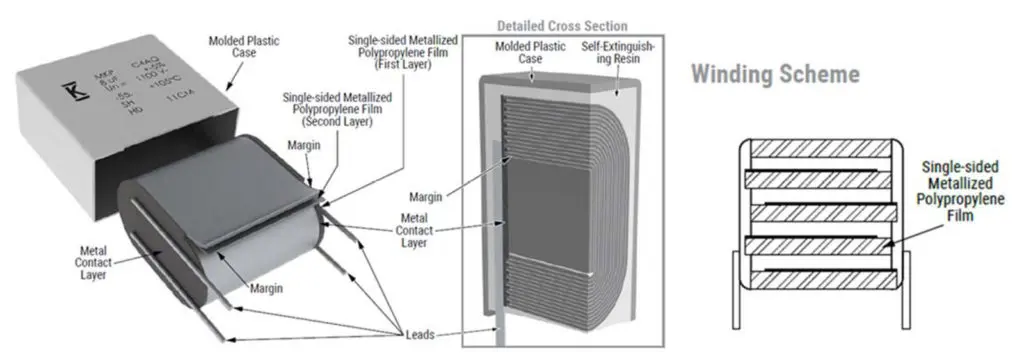
Just like MLCCs, film-CAPs are non-polar devices and have somewhat similar layered structure. In this case the dielectric layer, polymer film typically polypropylene (others include polystyrene, polycarbonate, etc.) 2-20 μm thick, is metalized with a few nm thick Al and/or Zn layer (which acts as the electrodes). A small “margin” of the film is left unmetallized on one end.
Hundreds or even thousands of these layers are stacked or wound together, with every other layer being displaced to one side (Fig. 18) and the margin being on the opposing end. End termination is then applied on each side, typically with the same metallization (Al or Zn) sprayed on it, followed by a solder layer, typically Sn. End termination makes the electrical connection to the thin metallization layer in each layer in the winding.
The external surface of the end termination provides solderable region and it also provides physical support to the winding. Depending on the design, electrical terminals are attached on each end and the whole assembly is put in a case which is filled with an epoxy or poly urethane (PU) resin. In some cases, this step is skipped, and the capacitor is used in naked/unpotted construction. A number of these capacitors could be joined together before encasing these, to achieve desired electrical properties.
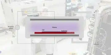
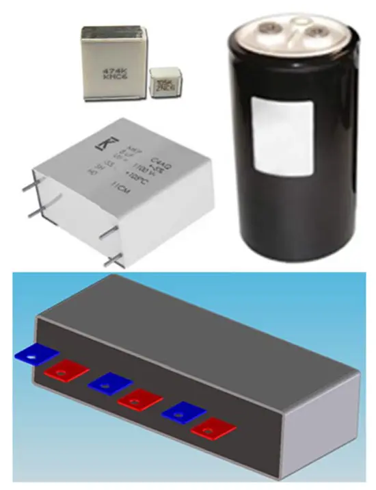
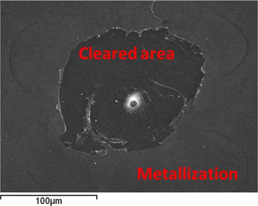
Film CAPS are available in variety of constructions, sizes and designs (Fig. 19) for different applications. The failure analyst needs to understand these before starting the FA. The film-CAPs are also very capable of self-healing, which can prevent catastrophic failure. If there is a dielectric breakdown, the energy released by the arcing (plasma discharge) at the breakdown site evaporates the thin metal layer in the surrounding areas of the fault site. This so-called “clearing phenomenon” isolates the fault site, thus restores low leakage current with a small capacitance drop (Fig. 20).
In extreme cases “clearing” can cause excessive amount of effective area loss, resulting in significant capacitance loss. Biaxially oriented polypropylene has the best self-healing properties and, therefore is used as the dielectric in high energy applications.
Low or no capacitance and high leakage or short are the two major failure modes of film CAPS. Although in some cases high ESR could result in failure as well. Low or no capacitance can typically result from disconnection of thin metallization layer to the end termination, or corrosion of the metallization layer itself. In either case the effective surface area decreases resulting in capacitance loss.
Another possibility is lack of electrical connection between the termination and external electrical lead. For film-CAPS with one stack/wound element (from now onward referred as “film wound”) similar to the one depicted in (Fig. 18), disconnection between either of the “leads” and the end termination will result in no capacitance (open failure mode). For film-CAPS with multiple “film wound” a lack of connection between one of these will result in low capacitance issue. Lack of good connection between “Leads” to end termination can result in high ESR resulting in localized heating which in turn causes further degradation of the joint thus making it a self-progressing process.
Thin spots and holes in the film can provide leakage paths. Entrapment of any hard particles in the film winding can create holes in the film as well, thus allowing opposing terminals to be in very close vicinity. This scenario upon voltage application can provide an electrical path resulting in high leakage or short.
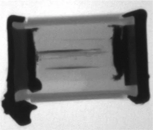
Bridging between two opposing terminals could also result from metallization of one film getting connected to both the terminals. This can happen during production, or localized heating in the CAP, or high temperature exposure especially during board mounting process. An extreme example of this type of failure detected by an X-ray (Fig. 21), revealed solder reflowed into the “film winding” thus bridging the opposite metallization layers resulting in a dead short.
Since the film-CAPS are made by winding the metallized film, it allows a unique FA approach for these, i.e. the film can be unwound after removing the casing and the end termination. This allows detailed visual examination of the foil in reflective as well as transmission modes for defects. Area of concern then can be further analyzed using optical and/or electron microscopy techniques.
SuperCapacitors
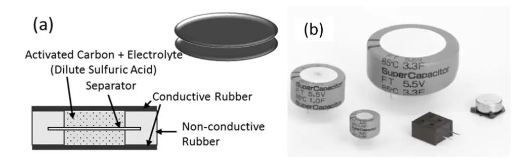
Super CAPS are polar devices and are much different than regular CAPS in their operations and applications. These CAPS have much higher capacitance than the regular CAPS, with lower voltage limits. These CAPS bridge the gap between regular CAPS and batteries. Unlike regular CAPS, there is no dielectric in Super CAPS.
Rather these consist of a conductive electrode and an electrolyte. Once voltage is applied the charge is stored electrostatically and/or electrochemically. Figure 22a shows basic base-cell of a super CAP, consisting of two opposing electrodes typically conductive rubbers, with a mixture of activated carbon and dilute sulfuric acid paste between two conductive rubber discs. An organic separator keeps the positive and negative ends isolated yet allows charge to travel across.
Sealing material and curing of the rubbers seal the base cell. A desired number of these base cells are stackedon top of each other and terminals connected to obtain the desired product (Fig. 22b).
Unlike other capacitors, typically super CAPS fail in high ESR or open mode. Most of these failures occur because of water evaporation from the electrolyte. Failure analysis involves external and internal examination with optical and X-ray analysis along with basic electrical testing. This is followed by decapsulation of the CAP to examine the individual cells. Cells are analyzed for any electrolyte leakage sites. The electrolyte leakage/evaporation could result from lack of proper sealing during manufacturing process, or exposure to high temperature.
In some extreme cases, very fast heating to higher temperature can result in pressure build up and explosion of the part. Like Al-CAPS, Super CAPS are not hermetically sealed and have an end of life, therefore knowing the part history is critical.
Inductors
The inductor (IND) is an electrical component that can store magnetic energy. These are used mainly for power conversion like DC/DC converter and noise reduction applications. Basically, an IND is comprised of a conductive coil and magnetic material. The conductive coil is generally made of insulation coated wire which is called “magnet wire or enameled wire”, copper trace, or sintered silver paste. The representative magnetic materials are ferrites and iron-based metal alloys.
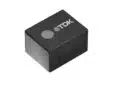
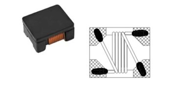
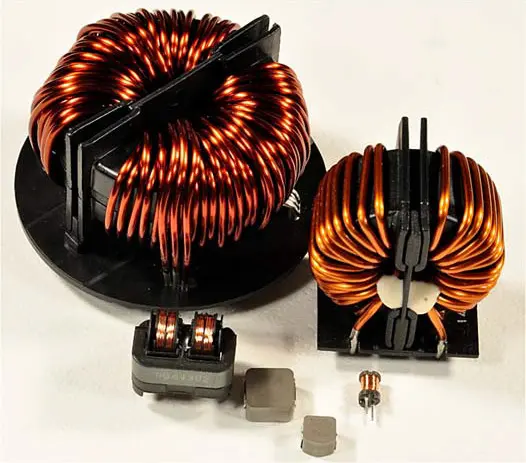
Based on the construction, INDS can be divided into two common types, Common Mode Choke Coil and Surface Mount Powder Choke Coil, (Fig. 23), both are discussed in the following.
Common Mode Choke Coil
Common Mode Choke Coil (CMCC) is used for common mode noise reduction in power line. It is normally comprised of toroidal core and wound wire. The core is ferrite, pressed metal powder, or laminated metal ribbon. Insulation coated copper wire is used for winding. The ends of the wound wire are used as the connecting terminals.
CMCC’s electric performance depends on the permeability of the magnetic material, core size, and number of turns of the wire. The core, which has some conductivity, is encased for keeping insulation between the wire and the core. The diameter of the wire is determined by its rated current. For high current ratings, sometimes two or three wires are wound simultaneously around the core, instead of one thicker wire, which might be difficult to wind to the core. Material of the core is determined by required permeability and environmental conditions such as temperature, humidity, and mechanical stresses.
CMCCs could fail open, short, or exhibit parametric losses. Shorting by insulation defect is the most common failure mode. Insulation coating of the wire could be damaged by mechanical stress, during winding, or the wire is over heated by excessive current (during application), and so on.
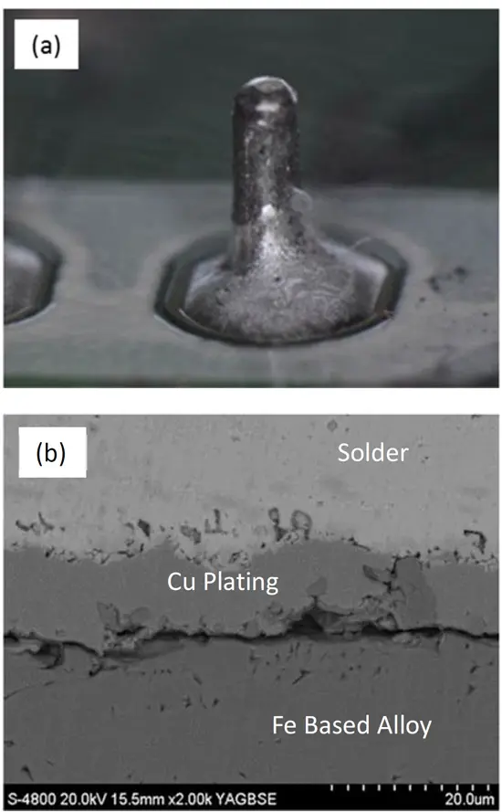
image and (b) SEM image showing delamination in a cross-sectioned view.
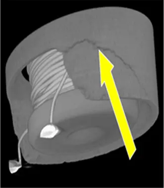
Open mode failure may occur by excess current and/or a defect in terminal soldering. A damaged core, such as cracking, may cause parametric changes because its magnetic properties are changed. This is especially true for a ferrite-based core: the ferrite being brittle in nature, can easily be damaged by mechanical or thermal shock. In one such example, external examination of a low inductance failure did not show any anomalies. Internal construction examination utilizing X-ray CT (Fig. 24) revealed the existence of a crack in a ferrite core. Decrease in the core size could lower the inductance. The nature of the crack suggests that the core was damaged by mishandling.
An open mode failure could occur by compromised lead connection. Fig. 25a shows a closeup of a terminal of an open IND after soldering operation. External examination did not reveal any apparent defect. The part was potted in an epoxy and cross-sectioned for an internal construction examination. SEMEDX analysis of the terminal solder interface showed delamination between the terminal (Fe-based alloy) and copper plating (under plating between terminal and solder).
These types of failures are typically attributed to an improper plating process. Application temperature variation can lead to parametric failures. Magnetic properties of materials are temperature dependent and above the Curie temperature, magnetism of the material is lost completely. Curie temperature is composition dependent, e.g. for ferrite-based materials it is between 120°C to 220°C, depending on composition.
Surface Mount Inductors
Surface Mount Inductors (SMI) are used for power conversion circuits such as DC/DC converters. They are comprised of preformed inner coil which is molded over using a composite material (mixture of a magnetic metal alloy’s powder and resin). The inner coil is made of round or squared wire with insulation coating. Insulation coating has two roles: insulating between adjacent wires and insulating between the coil and the over-molded material. The manufacturing process involves setting up the inner coil in a die, backfilling the die with composite material and pressing it, curing the resin and plating solder on the wire ends, and finally folding the wire ends to form terminals.
Surface Mount Powder Choke Coil could fail open, short or exhibit parametric losses. Improper conditions at pressing could damage the wire’s insulation by metal powder (part of composite) rubbing/pushing against it, consequently creating a short condition. This type of IND is attached to the board by two terminals, which supports its heavy body as well. Any damage by mechanical stress, especially vibration, can compromise either or both terminals, thereby creating an open condition. When vibration frequency is consistent with IND’s natural resonance frequency, these terminals might break resulting in an open mode failure.
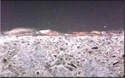
Surface oxidation and/or corrosion may occur because the composite material contains metal powder which is mainly iron. Such rust and corrosion may cause slight parametric change but typically are mere physical appearance issue. A cross sectional view of an IND, (Fig. 26), which had been exposed to high humidity for extended time, shows presence of rust just on the surface. It is most likely caused by peeling away of coating on metal powder on the surface.
This was a superficial cosmetic defect, as no penetration of rust was detected even after long exposure times. More importantly, no deterioration in magnetic characteristics was detected. Improvement of coating material and coating condition resulting in stronger adhesion eliminates even the surface rust.
Summary
The goal of passive components’ failure analysis (FA) is to determine the root cause for an electrical failure. The findings can be used by the manufacturers to improve upon the design, materials, and processes used to create their components. This leads to better quality and higher reliability components. The FA also provides feedback for the users to improve their handling, storage, and applications of these components.
The improved quality and application conditions of these components, help reduce and eliminate premature failures, and enhances the overall electronics’ performance and reliability.
To perform proper FA, an understanding of component construction is crucial. Typical construction of Ta, Alelectrolytic, Film, MLCC and Super CAPS along with Common Mode Choke Coil and Powder Mode Choke Coil Inductors are discussed. Initial examination and documenting the failure in as-received condition, common for all of these, is very critical and should be done.
For capacitors, typically high leakage or short condition results from either dielectric compromise or bridging across the positive and negative terminals, what causes this and how it occurs varies for the different CAPS. High ESR, low or no capacitance typically result from compromised connections, the cause of which varies depending on the capacitor type.
Mechanical damage, harsher environment along with some production defects are the dominant factors for Inductors failures.
Acknowledgments
Authors would like to acknowledge KEMET colleagues for their help in preparing and reviewing this chapter, especially A.Parker, B. Reeves, D.Hepp, P. Bryson, M. Fulton, Z. Dou, V.Andoralov, D. Adam, M. Wright, M. Michelazzi, D. Montanari, J. Chen, C. Fischer, C. MotaCaetano, A. Gurav, C. Riedl, J.Bultitude, O. Pirakaew, P. Khomwongthep, K. Oga and P.Lessner.
We would also like to thank J. Kaplan of Cornell Dubilier for his help.
References
[1] KEMET Electronics Corporation, www.kemet.com
[2] Ross, R., Microelectronics Failure Analysis Desk Reference 6th Edition, ASM International, (Ohio, 2011),pp. 111-120.
[3] www.avx.com
[4] www.cde.com
[5] www.murata.com
[6] www.vishay.com
[7] www.panasonic.com
[8] Qazi, J., “An Overview of Failure Analysis of Tantalum Capacitors”, Electronic Device Failure Analysis, Vol. 16, No. 2 (2014), pp.18-23.
[9] Ye. J, Stolarski, C., Yaun, M., “Conductive Polymer Based Tantalum Capacitors for Automotive Applications”, Tantalum International Study Center, 56th General Assembly Meeting, 2015.
[10]Freeman, Y., Hahn, R., Lessner, R., and Prymak, J., “Reliability and Critical Applications of Tantalum Capacitors”, Capacitors and Resistors Technology Symposium, Electronic Components, Assemblies and Materials Association (ECA), March 2007.
[11] Freeman, Y., “Effects of Thermal Oxide on Anodic Oxide of Ta”, Capacitors and Resistors Technology
The article has been published on Passive Components Blog passive-component.eu under Copyright © 2019 ASM International® www.asminternational.org and permission from authors.
The full book can be accessed at following address https://doi.org/10.31399/asm.mfadr7.9781627082471