Passive Components Blog
No Result
View All Result
  • Home
  • NewsFilter
    • All
    • Aerospace & Defence
    • Antenna
    • Applications
    • Automotive
    • Capacitors
    • Circuit Protection Devices
    • electro-mechanical news
    • Filters
    • Fuses
    • Inductors
    • Industrial
    • Integrated Passives
    • inter-connect news
    • Market & Supply Chain
    • Market Insights
    • Medical
    • Modelling and Simulation
    • New Materials & Supply
    • New Technologies
    • Non-linear Passives
    • Oscillators
    • Passive Sensors News
    • Resistors
    • RF & Microwave
    • Telecommunication
    • Weekly Digest

    Modelithics Library for MATLAB: Measurement-Based Models for Microwave and RF Passive Components

    Bourns Extends Multilayer Chip Inductors Offer for RF and Wireless Designs

    Researchers developed a polymer capacitor by combining two cheap, commercially available plastics. The new polymer capacitor makes use of the transparent material — pictured here, with vintage Penn State athletic marks visible through it — to store four times the energy and withstand significantly more heat.  Credit: Penn State

    Penn State Demonstrated Polymer Alloy Capacitor Film with 4× Energy Density up to 250C

    ECIA January 2026 Reports Strong Sales Confidence

    Vishay Unveils Ultra-Compact 0201 Thick Film Chip Resistors

    Würth Elektronik Component Data Live in Accuris

    Coilcraft Releases Automotive Common Mode Chokes

    MLCC Manufacturers Consider Price Increase as AI Demand Outpaces Supply

    YAGEO Extends Antenna Portfolio with Wi‑Fi 6E/7 and Tri‑band GNSS Solutions

    Trending Tags

    • Ripple Current
    • RF
    • Leakage Current
    • Tantalum vs Ceramic
    • Snubber
    • Low ESR
    • Feedthrough
    • Derating
    • Dielectric Constant
    • New Products
    • Market Reports
  • VideoFilter
    • All
    • Antenna videos
    • Capacitor videos
    • Circuit Protection Video
    • Filter videos
    • Fuse videos
    • Inductor videos
    • Inter-Connect Video
    • Non-linear passives videos
    • Oscillator videos
    • Passive sensors videos
    • Resistor videos

    2026 Power Magnetics Design Trends: Flyback, DAB and Planar

    Enabling Software‑Defined Vehicle Architectures: Automotive Ethernet and Zonal Smart Power

    Calculating Resistance Value of a Flyback RC Snubber 

    One‑Pulse Characterization of Nonlinear Power Inductors

    Thermistor Linearization Challenges

    Coaxial Connectors and How to Connect with PCB

    PCB Manufacturing, Test Methods, Quality and Reliability

    Transformer Behavior – Current Transfer and Hidden Feedback

    Choosing the Right Capacitor: The Importance of Accurate Measurements

    Trending Tags

    • Capacitors explained
    • Inductors explained
    • Resistors explained
    • Filters explained
    • Application Video Guidelines
    • EMC
    • New Products
    • Ripple Current
    • Simulation
    • Tantalum vs Ceramic
  • Knowledge Blog
  • DossiersNew
  • Suppliers
    • Who is Who
  • PCNS
    • PCNS 2025
    • PCNS 2023
    • PCNS 2021
    • PCNS 2019
    • PCNS 2017
  • Events
No Result
View All Result
Passive Components Blog
No Result
View All Result

Five Key Filter Specifications

4.1.2023
Reading Time: 5 mins read
A A

In this article published by Knowles Precision Devices Blog simplify filter selection by providing an overview and reference point for key five of the most commonly used filter technology specifications.

The basic filter circuits were explained in this article Basic Filter Circuits Explained.

RelatedPosts

Knowles Doubles Capacitance of its Class I Ceramic C0G Capacitors

3-Phase EMI Filter Design, Simulation, Calculation and Test

Knowles Releases High Q Non-Magnetic X7R MLCCs for Medical Imaging

To select the ideal filter for your application, you first need to understand how to define your filtering requirements as these requirements will ultimately determine the specifications of your filter.

While there are many possible filter specifications, this post covers the following five key specifications we feel are crucial to understand:

  • Center frequency
  • Bandwidth
  • Insertion loss
  • Out-of-band rejection
  • Selectivity

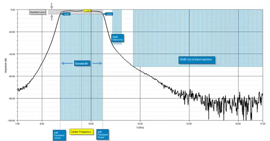
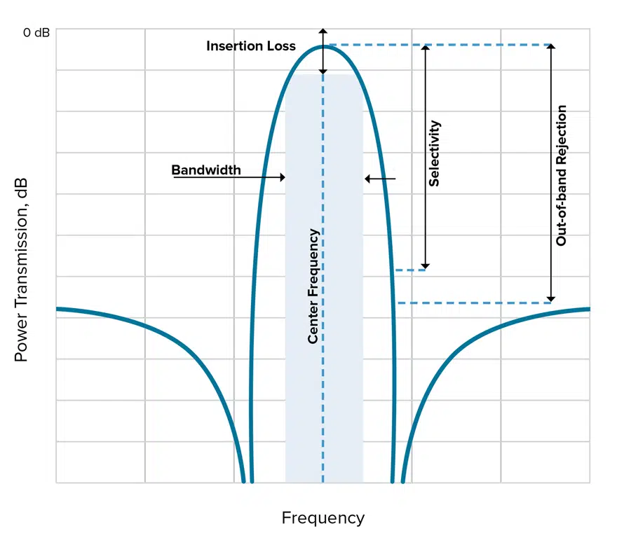
In Figure 1, you can see each of these five metrics called out on a plot for a typical bandpass filter response.

Figure 1. An example of a typical bandpass filter response with the five key filter specifications we are examining called out.

Let’s dive into each of these specifications in more detail.

Figure 2. In this example, fL is the lower cutoff of this bandpass filter while fH is the upper cutoff, therefore, f0 is the center frequency. 

Center Frequency

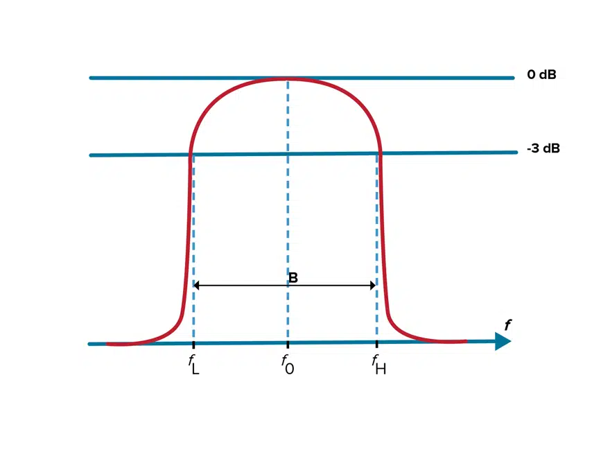
Center frequency is defined as the geometric or arithmetic mean of the upper and lower cutoff frequencies or 3dB points of the bandpass filter. The center frequency in the example in Figure 2 is identified as f0.

Bandwidth

Bandwidth is the width of the passband of the bandpass filter and is expressed as the frequency difference between the lower and upper 3 dB points. When it comes to bandwidth, we can also look at the relative or fractional bandwidth of the filter, which is the ratio of a filter’s bandwidth to its center frequency. As shown in Figure 3, different filter technologies are capable of different fractional bandwidths.

Figure 3. This graphic shows fractional bandwidths across frequencies for a variety of filter types.

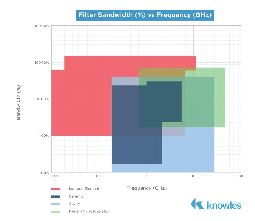
As you can see in Figure 3, it is possible to have a fractional bandwidth that is greater than 100 percent. For example, if your filter has a 2 – 18GHz range, the center frequency is 10GHz and the bandwidth is 16GHz, which would make the fractional bandwidth 160 percent.

Insertion Loss

Insertion loss is the ratio of a signal level in a test configuration without a filter present (|V1|) to that when the filter is present (|V2|) and is calculated as shown in the equation below.

It is important to note that you should consider insertion loss as a specification on both the Tx side since power is a system cost driver, as well as on the Rx side because loss impacts the overall noise figure of the receiver.

Out-of-Band Rejection

A passband filter cannot allow interference from signals outside the bandwidth of interest. Therefore, your filter needs to have the ability to reject (attenuate) out-of-band emissions. These out-of-band emissions are far away from the band of interest (refer back to Figure 1) but can still interfere with the signals within the passband through effects such as aliasing. More specifically, in their recommendation document on “Unwanted Emissions in the Out-of-Band Domain,” the International Telecommunications Union (ITU) defines out-of-band emissions as “Emission on a frequency or frequencies immediately outside the necessary bandwidth which results from the modulation process, but excluding spurious emissions.”

Selectivity

Selectivity is a measurement of a filter’s ability to pass or reject specific frequencies closer to the band of interest. Selectivity is also sometimes described by talking about the size of the transition band necessary to get from the pass band to a certain rejection level, and often the size of the transition band is expressed as a percentage of the center frequency. Thus, a filter’s selectivity can tell us how much of the total bandwidth needs to be dedicated to transition bands.

If a filter has high selectivity, smaller transition bands are needed, which means smaller guard bands are necessary and less bandwidth is wasted implementing these features. Therefore, high selectivity is crucial in environments where adjacent channels are close together as high selectivity enables RF system designers to most efficiently use the available bandwidth. Additionally, selectivity is a critical specification for determining a filter’s suitability for a given application because a system’s transmission and reception characteristics are given in terms of both insertion loss in the pass band as well as clearly prescribed attenuation requirements in the stop band.

Putting it All Together: A Real-World Filter Example

While we started this post with a hypothetical example of based on typical bandpass response with, Figure 4 shows these five specifications called out on an S21 plot for one of our 9.5GHz surface-mount bandpass catalog filters, (example Knowles B095MB1S).

Figure 4. These five key specifications identified on an S21 plot of one of popular filters B095MB1S.

Related

Source: Knowles Precision Devices

Recent Posts

2026 Power Magnetics Design Trends: Flyback, DAB and Planar

13.2.2026
47

Mechanical Drift Indicator of Tantalum Capacitor Anodes Degradation under Reverse Bias

3.2.2026
50

Enabling Software‑Defined Vehicle Architectures: Automotive Ethernet and Zonal Smart Power

2.2.2026
43

Calculating Resistance Value of a Flyback RC Snubber 

2.2.2026
61

Power Electronics Tools for Passives and Magnetic Designs

3.2.2026
114

DC/DC Push‑Pull Converter vs PSFB Design Guide

12.1.2026
295

Energy-Controlled Structural Evolution of Amorphous Ta₂O₅ in Tantalum Anodes

6.1.2026
77

Towards Green and Sustainable Supercapacitors

30.12.2025
65

Mechano-Chemical Model of Sintered Tantalum Capacitor Pellets

29.12.2025
73

Upcoming Events

Feb 24
16:00 - 17:00 CET

Mastering Galvanic Isolation: Ensuring Safety in Power Electronics

Mar 3
16:00 - 17:00 CET

Cybersecurity at the Eleventh Hour – from RED to CRA – Information and Discussion

Mar 21
All day

PSMA Capacitor Workshop 2026

View Calendar

Popular Posts

  • Buck Converter Design and Calculation

    0 shares
    Share 0 Tweet 0
  • Boost Converter Design and Calculation

    0 shares
    Share 0 Tweet 0
  • LLC Resonant Converter Design and Calculation

    0 shares
    Share 0 Tweet 0
  • Flyback Converter Design and Calculation

    0 shares
    Share 0 Tweet 0
  • Ripple Current and its Effects on the Performance of Capacitors

    3 shares
    Share 3 Tweet 0
  • Dual Active Bridge (DAB) Topology

    0 shares
    Share 0 Tweet 0
  • What is a Dielectric Constant and DF of Plastic Materials?

    4 shares
    Share 4 Tweet 0
  • MLCC and Ceramic Capacitors

    0 shares
    Share 0 Tweet 0
  • MLCC Case Sizes Standards Explained

    0 shares
    Share 0 Tweet 0
  • SEPIC Converter Design and Calculation

    0 shares
    Share 0 Tweet 0

Newsletter Subscription


Passive Components Blog

© EPCI - Leading Passive Components Educational and Information Site

  • Home
  • Privacy Policy
  • EPCI Membership & Advertisement
  • About

No Result
View All Result
  • Home
  • Knowledge Blog
  • PCNS

© EPCI - Leading Passive Components Educational and Information Site

This website uses cookies. By continuing to use this website you are giving consent to cookies being used. Visit our Privacy and Cookie Policy.
Go to mobile version