


This article explains flying capacitor circuit configuration features and benefits.
The flying-capacitor size is significantly smaller than the required DC-link capacitor used in traditional booster topologies with the same power rating nevertheless there are some issues to be addressed with this topology. The article is based on Knowles blog article written by Jordan Yates and EE Power article by Viktor Antony.
Key Takeaways
- Flying capacitors are smaller, efficient alternatives to traditional DC-link capacitors in power electronics like inverters and battery management systems.
- They help balance voltage levels, enhance power quality, and improve system efficiency by storing and releasing energy as needed.
- Key considerations for flying capacitors include sizing, voltage balancing, and pre-charging to prevent system failures during operational changes.
- Ceramic capacitors provide several advantages, such as high dielectric constant, non-polarity, low ESR, and compact size, making them ideal for flying capacitor applications.
- In conclusion, flying capacitors offer a cost-effective solution with significant benefits for solar inverters and EV applications.
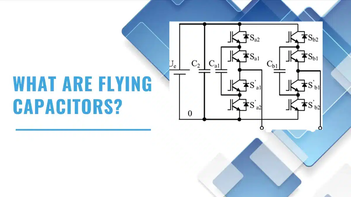
As demand for high-efficiency and high-power-density inverters continues to grow, the so-called “flying” capacitor multilevel inverter is emerging as a strong choice for many power electronics systems.
Since these capacitors can “float” to different electric potentials depending on the connected semiconductor switching structure and state, they help balance out voltage level differences due to manufacturing tolerances, temperature variations, and other factors.
These capacitors are also helpful in balancing voltage across the structure by temporarily storing and releasing energy as needed, increasing power density and quality, and optimizing the use of existing voltage availability.
What is a Flying Capacitor?
A flying capacitor is a type of capacitor that is used in multi-level inverters, common in applications such as electric vehicle (EV) inverters, battery management systems (BMSs), renewable energy systems, and other power electronics. The main function of a flying capacitor is to store and transfer energy between different levels of the inverter, using multiple capacitors connected in series and parallel to produce a desired voltage level.
Flying Capacitor Topology Variants
Flying capacitors are commonly used in several multilevel converter and booster structures, each with different trade‑offs in complexity, number of devices, and performance. In multilevel inverters, flying‑capacitor (FC) topologies form additional intermediate voltage levels by inserting series capacitors between the DC link and the phase outputs, which reduces dv/dt stress on the semiconductors and the motor or transformer insulation.
Compared to neutral‑point‑clamped (NPC) or active NPC (ANPC) multilevel converters, flying‑capacitor structures eliminate the need for a tightly controlled neutral point but require additional capacitors whose voltages must be kept balanced. FC boosters, like the solar‑inverter example in this article, use a flying capacitor to achieve effective frequency multiplication and reduced current ripple, often allowing smaller magnetics and lower‑voltage semiconductors for the same power rating.
Example I. : Flying Capacitors in a Battery Management System
Popular application areas for flying capacitors include EVs and solar inverters due to their lightweight, compact nature, and ability to help even out voltage and extend longevity of components. For example, within an EV BMS, a flying capacitor can be used to smooth out fluctuations in the voltage of the battery pack. The battery pack in an EV typically consists of many individual cells connected in series and parallel, and these cells can have slight variations in their voltage levels due to manufacturing tolerances, temperature variations, and other factors.
The flying capacitor can be used to balance the voltage across the cells by temporarily storing and releasing energy as needed. This helps ensure all the cells in the battery pack are operating at optimal voltage levels, prolonging the overall life of the battery pack. Additionally, the flying capacitor can help reduce the harmonic distortion of the voltage waveform, improving the overall power quality of the system.
Example II. : High Efficiency Solar Inverters
Using high-efficiency solar inverters is reaching more and more popularity in a design, however, it is not the most economical. To achieve a cost efficient solution, not only the inverter has to be low cost and high efficient, but also the booster stage.
The flying-capacitor booster solution can increase the efficiency while being still cost-efficient. However, it has also some challenges as capacitor sizing, balancing and the pre-charge.
Flying Capacitor Design Considerations
Sizing of the Flying-Capacitor
The voltage supplied by a flying-capacitor has a key role in this topology. To keep the voltage ripple on the capacitor low, a suitable capacitor size is needed. To determine the needed capacitance, the switching frequency and the maximum allowed voltage ripple need to be considered. The size of the capacitance can be calculated as:
Example: Flying Capacitor Sizing
As an example, consider a solar inverter booster stage where the peak inductor current is 20 A, the switching frequency is 50 kHz, and the maximum allowed flying‑capacitor voltage ripple is 2 V. Using the sizing relation shown above, this results in a required capacitance on the order of a few tens of microfarads, depending on the exact current waveform and modulation strategy.
In practice, designers often implement this value as a parallel array of MLCCs to share RMS current and reduce effective ESR. The final value should be verified under worst‑case conditions (maximum current, minimum switching frequency, highest operating temperature), since both MLCC capacitance and ESR vary with DC bias and temperature.
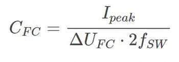
where dUFC is the maximum allowed voltage ripple, Ipeak is the maximum current, and fSW is the switching frequency of the transistors.
Balancing of the Capacitor Voltage
For proper operation, the flying‑capacitor voltage must track approximately half of the output voltage, and this condition has to be maintained over all load and operating modes. This balance is typically achieved by appropriate selection of switching states in the modulation scheme, so that the average charge taken from and returned to the capacitor over a switching period is equal.
In digitally controlled converters, redundant switching states can be used to correct small deviations in flying‑capacitor voltage without changing the output waveform. By slightly biasing the use of states that charge or discharge the capacitor, the controller can compensate manufacturing tolerances, temperature drift, and aging of the capacitor. Monitoring the flying‑capacitor voltage and implementing simple PI control around the reference (typically Vout/2) improves robustness and allows the converter to ride through transient conditions without over‑ or under‑voltage on the capacitor.
Pre-Charge of the Flying Capacitor
In case when all the control signals of used transistors are low, the flying-capacitor voltage cannot be regulated. In that operation an extra effort is needed to keep the flying-capacitor voltage on the safe side. Failing to eliminate the overvoltage on the semiconductors may cause a fatal error in the system.
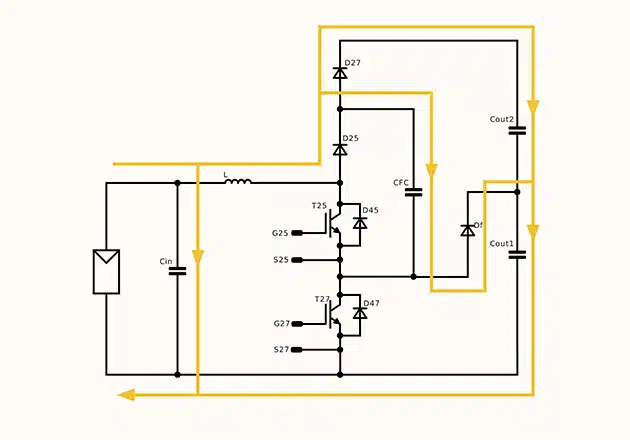
There is a method proposed by Mitsubishi Electric Corporation [1] to protect the flying capacitor booster, when there are no control signals (e.g.: during startup).
There are two operation modes, when all the transistors are OFF: 1) When the input is applied and the output is equal with the input (e.g.: startup), and 2) when the input is zero and the output is not. This happens, for example, when one string is not connected to the circuit and other boosters are working. In both two cases the voltage of the flying-capacitor is zero, and the voltage sharing of the two transistors is not defined. To keep the voltage level of the semiconductors below the breakdown voltage, additional balancing has to be used.
During startup the current flows through the two diodes and charge the output capacitance. In this case the output voltage is equal to the input voltage, while the flying-capacitor voltage is zero. This is dangerous for the lower switch. To eliminate this problem, another current path has to be added, in which the current can charge also the flying capacitor. For this a diode can be used, a cathode of which has to be connected to a capacitive voltage divider, where the lower point of the flying-capacitor is clamped at the half of the DC-link voltage. This can be seen on Figure 1.
Ceramic Capacitor Benefits
Ceramic capacitors can offer number of benefits as flying capacitors. They are non-polar devices unlike the other electrolytic capacitors and offer high capacitance and voltage range compare to the other electrostatic capacitor types. Because of the physical properties of ceramic capacitors, many companies are choosing this route to leverage the benefits of ceramic, including:
- High Dielectric Constant: Ceramic capacitors can store a large amount of energy in a small package.
- Non-Polar Capacitor: Ceramic capacitors are non-polar devices, so the voltage polarity is not of a concern.
- Low Equivalent Series Resistance (ESR): Ceramic capacitors can transfer energy quickly and efficiently.
- Size and Lifespan: Ceramic capacitors are small and lightweight with a long lifespan, which helps reduce the size and weight of the inverter, making them ideal for use in compact electronic devices.
- Speed of Transfer: Ceramic capacitors can quickly transfer energy between different levels of an inverter, helping reduce losses and improve the overall efficiency of the system.
Non‑Ideal Effects and Reliability Considerations
In high‑frequency flying‑capacitor applications, non‑ideal parameters such as equivalent series resistance (ESR) and equivalent series inductance (ESL) have a strong influence on losses, temperature rise, and EMI. The RMS ripple current through the capacitor can be high, so even low ESR values translate into measurable self‑heating, which must be considered in the thermal design.
Ceramic capacitors also exhibit capacitance reduction with applied DC bias, temperature, and aging, which effectively increases the in‑circuit voltage ripple compared to the nominal design calculation. For reliable operation, it is good practice to derate both voltage and capacitance, select parts with adequate ripple current capability, and ensure sufficient margin to withstand transient overvoltages during startup and fault conditions. In many designs, this means combining several MLCCs in parallel and using conservative voltage derating (for example, using a 100 V‑rated device in a 50–60 V application).
Layout Considerations and EMC
PCB layout has a significant impact on the performance of flying‑capacitor circuits because the capacitor, switches, and associated traces form high‑di/dt current loops. To minimise parasitic inductance and ringing, the flying capacitor should be placed as close as possible to the associated semiconductor devices and connected with wide, short traces or planes.
Careful loop‑area reduction and solid ground or reference planes help limit radiated and conducted EMI, while also reducing voltage overshoot on the switches. Where possible, symmetric layouts between phases or channels improve balancing and reduce circulating currents, and additional damping or snubber networks can be used if measured waveforms exhibit excessive ringing.
Conclusion
The flying-capacitor booster is a high-efficient, low cost solution for solar inverter or battery management applications. The main advantages are the frequency multiplication, the lower semiconductor voltage, the lower voltage and current ripple, the lower switching losses, and the low EMI emission.
The flying-capacitor size is significantly smaller than the required DC-link capacitor used in traditional booster topologies with the same power rating. The challenge is to regulate the voltage of the flying-capacitor especially when all the transistors are in OFF state (i.e.: before the converter is turned on). The balancing can be achieved by state regulation. Also the pre-charge challenge can be solved easily by additional diodes based on Mitsubishi Electric Corporation’s patent [1]. With these diodes the flying-capacitor booster is a cost efficient alternative for the other booster solutions with higher efficiency.
References
[1] T. Okuda and H. Ito, “DC/DC POWER CONVERSION APPARATUS”. United States Patent US 2013/0021011 A1, 24 01 2013.
Flying Capacitors – FAQ
A flying capacitor is a capacitor used in multilevel inverters and power electronics systems. It temporarily stores and transfers energy between voltage levels, helping to balance voltage differences caused by tolerances, temperature, or load variations.
They are widely used in electric vehicle battery management systems (BMS), renewable energy inverters such as solar systems, and other high-efficiency power electronics applications.
Flying capacitors improve power density, reduce voltage ripple, balance cell voltages, and enhance efficiency. When ceramic capacitors are used, they also provide long lifespan, low ESR, and compact size.
Key challenges include correct sizing to minimize ripple, maintaining voltage balance at half the output voltage, and ensuring safe pre-charge during startup to avoid semiconductor stress.
The flying‑capacitor voltage is balanced by appropriate modulation of the switches, using redundant states and feedback control to ensure the average charge taken from and returned to the capacitor is equal over each switching cycle.
The most important layout practices are to minimise loop area between the capacitor and switches, use short and wide connections with solid reference planes, and place the flying capacitor physically close to the switching devices to control parasitics and EMI.
How to Design a Flying Capacitor Circuit
- Define system requirements
Determine the inverter application (EV, solar, or BMS) and establish the required voltage and current ratings.
- Calculate capacitor size
Use switching frequency, peak current, and maximum allowed voltage ripple to calculate the required capacitance value.
- Ensure voltage balancing
Implement control strategies to regulate the flying capacitor voltage at half of the output voltage for stable operation.
- Add pre-charge protection
Incorporate additional diodes or circuits to safely pre-charge the capacitor during startup, preventing overvoltage stress on semiconductors.
- Verify thermal and reliability margins
Evaluate capacitor ESR, RMS ripple current, DC‑bias derating, and temperature rise to ensure adequate lifetime margins under worst‑case operating conditions.
- Optimise layout and EMI performance
Place flying capacitors close to the switches, minimise current loop areas, and validate waveforms and emissions in the lab to fine‑tune parasitics and any required damping networks.
- Select capacitor type
Consider ceramic capacitors for their non-polarity, low ESR, compact size, and long lifespan, ensuring high efficiency and reliability. Electrolytic capacitors may provide higher capacitance value but limitation as polar devices. Film capacitors may work for higher voltages but it may be more bulky and limited by temperature.


