Passive Components Blog
No Result
View All Result
  • Home
  • NewsFilter
    • All
    • Aerospace & Defence
    • Antenna
    • Applications
    • Automotive
    • Capacitors
    • Circuit Protection Devices
    • electro-mechanical news
    • Filters
    • Fuses
    • Inductors
    • Industrial
    • Integrated Passives
    • inter-connect news
    • Market & Supply Chain
    • Market Insights
    • Medical
    • Modelling and Simulation
    • New Materials & Supply
    • New Technologies
    • Non-linear Passives
    • Oscillators
    • Passive Sensors News
    • Resistors
    • RF & Microwave
    • Telecommunication
    • Weekly Digest

    How to Manage Supercapacitors Leakage Current and Self Discharge 

    Qualification of Commercial Supercapacitors for Space Applications

    Experimental Evaluation of Wear Failures in SMD Inductors

    Resonant Capacitors in High-Power Resonant Circuits

    a Schematic diagram of the BNT-based components constructed based on the entropy-increase strategy. b Digital photograph, cross-sectional SEM image, and EDS mappings of the MLCCs. c Unipolar P-E loops of MLCCs as a function of applied E. d Wrec and η of the MLCCs as a function of applied E. The comparison of (e) Wrec and η, (f) η and UF of the MLCCs with those of other recently reported state-of-the-art MLCCs. source: Nature Communications

    Researchers Proposed Enhanced Energy Storage MLCC

    Littelfuse Releases First Reflow-Compatible Illuminated Tactile Switch

    Vishay Unveils 5W Power Metal Strip Resistor in Compact 1206 Case Size

    Improving SMPS Performance with Thermal Interface Material

    Polymer Tantalum Capacitors Beyond AEC-Q200 LEO Satellites

    Trending Tags

    • Ripple Current
    • RF
    • Leakage Current
    • Tantalum vs Ceramic
    • Snubber
    • Low ESR
    • Feedthrough
    • Derating
    • Dielectric Constant
    • New Products
    • Market Reports
  • VideoFilter
    • All
    • Antenna videos
    • Capacitor videos
    • Circuit Protection Video
    • Filter videos
    • Fuse videos
    • Inductor videos
    • Inter-Connect Video
    • Non-linear passives videos
    • Oscillator videos
    • Passive sensors videos
    • Resistor videos

    Efficient Power Converters: Duty Cycle vs Conduction Losses

    Ripple Steering in Coupled Inductors: SEPIC Case

    SEPIC Converter with Coupled and Uncoupled Inductors

    Coupled Inductors in SEPIC versus Flyback Converters

    Non-Linear MLCC Class II Capacitor Measurements Challenges

    Percolation Phenomenon and Reliability of Molded Power Inductors in DC/DC converters

    Root Causes and Effects of DC Bias and AC in Ceramic Capacitors

    How to Calculate the Output Capacitor for a Switching Power Supply

    Switched Capacitor Converter Explained

    Trending Tags

    • Capacitors explained
    • Inductors explained
    • Resistors explained
    • Filters explained
    • Application Video Guidelines
    • EMC
    • New Products
    • Ripple Current
    • Simulation
    • Tantalum vs Ceramic
  • Knowledge Blog
  • Suppliers
    • Who is Who
  • Events
No Result
View All Result
Passive Components Blog
No Result
View All Result

How to Manage Supercapacitors Leakage Current and Self Discharge 

1.10.2025
Reading Time: 4 mins read
A A

The paper “How to Manage Leakage Current and Self Discharge of EDLC Capacitors” was presented by Gerald Tatschl, Vishay BCcomponents, Klagenfurt am Wörthersee, Austria at the 5th PCNS Passive Components Networking Symposium 9-12th September 2025, Seville, Spain as paper No. 6.3.

Introduction

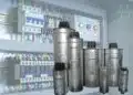
Electric double-layer capacitors (EDLCs), also known as supercapacitors, have been in use for more than 50 years, offering a bridge between traditional aluminum electrolytic capacitors and rechargeable batteries.

RelatedPosts

Qualification of Commercial Supercapacitors for Space Applications

Experimental Evaluation of Wear Failures in SMD Inductors

Resonant Capacitors in High-Power Resonant Circuits

Their extremely high capacitance is achieved through a combination of activated carbon with a large surface area, highly conductive liquid electrolytes, and the physical phenomenon of double layers. These devices deliver high discharge currents, making them useful in applications ranging from energy storage to backup power and energy harvesting systems.

Key Points

  • EDLCs store energy through the double-layer effect, allowing rapid and reversible charge exchange.
  • They can endure over one million charge and discharge cycles without significant degradation.
  • Self-discharge and leakage current are critical factors affecting long-term energy retention.
  • Both self-discharge and leakage current are highly influenced by temperature and charging history.
  • Leakage current declines over time but increases with higher temperatures.

Extended Summary

EDLCs serve as effective energy storage solutions where rapid energy delivery and high peak currents are required. Their large capacitance comes from the separation of charges in an atomic-scale double layer within the porous activated carbon electrodes. This architecture allows the stored charge to be accessed quickly and repeatedly with minimal performance loss.

One of the primary considerations in EDLC design is self-discharge, which refers to the natural voltage decay that occurs once a charged capacitor is disconnected from its power source. This phenomenon is driven by residual leakage current and is sensitive to several factors, including the charging duration, the applied voltage, and the ambient temperature. A fully charged EDLC may retain its charge for weeks at room temperature, but this holding time decreases significantly at higher temperatures, sometimes dropping to hours. Moreover, the initial voltage drop is more prominent at higher charging voltages, and longer charging periods generally improve self-discharge performance.

Leakage current is another critical aspect of EDLC behavior, defined as the small, residual current that persists after a capacitor has stabilized at a constant voltage. This current is influenced by the internal structure and materials of the capacitor, including electrode properties, electrolyte composition, and aging effects. Leakage current is initially high but decays exponentially over time. It is typically specified at 72 hours and at room temperature, often in the microampere-per-farad range, decreasing to nanoampere levels after extended charging.

Temperature plays a dual role in EDLC performance. It accelerates both self-discharge and leakage current, effectively acting as a multiplier rather than resetting the current behavior. Even when the temperature cycles between high and low values, the leakage current returns to its previous state at the respective conditions within hours. This characteristic underscores the importance of thermal management in applications requiring long energy retention.

EDLCs are highly scalable and can be configured in series and parallel to meet various voltage and energy requirements. They are increasingly used in automotive systems, renewable energy applications, and critical backup solutions in medical and data storage sectors, where understanding and managing self-discharge and leakage current is essential for reliable performance.

Conclusion

Self-discharge and leakage current are key factors that define the long-term energy retention of EDLC supercapacitors. While both are influenced heavily by temperature and charging conditions, they are distinct phenomena that must be considered separately in system design. By optimizing charging strategies and managing thermal conditions, engineers can maximize the performance and reliability of EDLC-based energy storage systems.

6_3_Vishay How to Manage Leakage Current and Self Discharge of EDLC CapacitorsDownload

Related

Source: PCNS

Recent Posts

Qualification of Commercial Supercapacitors for Space Applications

1.10.2025
2

Experimental Evaluation of Wear Failures in SMD Inductors

1.10.2025
2

Resonant Capacitors in High-Power Resonant Circuits

1.10.2025
3
a Schematic diagram of the BNT-based components constructed based on the entropy-increase strategy. b Digital photograph, cross-sectional SEM image, and EDS mappings of the MLCCs. c Unipolar P-E loops of MLCCs as a function of applied E. d Wrec and η of the MLCCs as a function of applied E. The comparison of (e) Wrec and η, (f) η and UF of the MLCCs with those of other recently reported state-of-the-art MLCCs. source: Nature Communications

Researchers Proposed Enhanced Energy Storage MLCC

1.10.2025
2

Littelfuse Releases First Reflow-Compatible Illuminated Tactile Switch

1.10.2025
1

Vishay Unveils 5W Power Metal Strip Resistor in Compact 1206 Case Size

1.10.2025
2

Improving SMPS Performance with Thermal Interface Material

30.9.2025
5

Polymer Tantalum Capacitors Beyond AEC-Q200 LEO Satellites

30.9.2025
16

Components Thermal and Frequency Challenges in 6G Base Stations

30.9.2025
8

Development of Nitrogen-Doped Graphene Supercapacitors 

30.9.2025
6

Upcoming Events

Sep 30
September 30 @ 12:00 - October 2 @ 14:00 EDT

MIL-Std-883 TM 2010

Oct 8
11:00 - 12:00 CEST

PCB Online Shop – simply “Made in Germany” by Würth Elektronik

Oct 14
16:00 - 17:00 CEST

Smart Sensors, Smarter AI: Building Reliable Edge Systems

Oct 17
12:00 - 14:00 EDT

External Visual Inspection per MIL-STD-883 TM 2009

Oct 20
October 20 - October 23

Digital WE Days 2025 – Virtual Conference

View Calendar

Popular Posts

  • Buck Converter Design and Calculation

    0 shares
    Share 0 Tweet 0
  • Boost Converter Design and Calculation

    0 shares
    Share 0 Tweet 0
  • Flyback Converter Design and Calculation

    0 shares
    Share 0 Tweet 0
  • LLC Resonant Converter Design and Calculation

    0 shares
    Share 0 Tweet 0
  • Dual Active Bridge (DAB) Topology Explained

    0 shares
    Share 0 Tweet 0
  • SEPIC Converter Design and Calculation

    0 shares
    Share 0 Tweet 0
  • What is a Dielectric Constant and DF of Plastic Materials?

    4 shares
    Share 4 Tweet 0
  • Ripple Current and its Effects on the Performance of Capacitors

    3 shares
    Share 3 Tweet 0
  • MLCC and Ceramic Capacitors

    0 shares
    Share 0 Tweet 0
  • Flying Capacitors Explained

    0 shares
    Share 0 Tweet 0

Newsletter Subscription


Passive Components Blog

© EPCI - Leading Passive Components Educational and Information Site

  • Home
  • Privacy Policy
  • EPCI Membership & Advertisement
  • About

No Result
View All Result
  • Home
  • Knowledge Blog
  • Premium Suppliers

© EPCI - Leading Passive Components Educational and Information Site

This website uses cookies. By continuing to use this website you are giving consent to cookies being used. Visit our Privacy and Cookie Policy.
Go to mobile version