


This article elaborates on the properties and design of input filters for DC/DC converter applications. The post is based on Würth Elektronik‘s “DC/DC Converter Handbook” which can be ordered from WE website here. Published under permission from Würth Elektronik.
Input filters at the DC/DC converter input have several roles: they limit differential‑mode ripple current and voltage, help the design meet conducted EMI requirements, protect the upstream source, and preserve converter control‑loop stability. The focus of this article is on differential‑mode LC input filters for non‑isolated and isolated DC/DC converters, with buck converters used as the main example because they are especially sensitive to input impedance and ripple. Common‑mode noise suppression, layout for radiated EMI and surge/transient protection are only briefly mentioned here and are covered in more detail in dedicated EMI and circuit protection articles on this blog.
Key Takeaways
- Input filters for DC/DC converters are essential to manage voltage dips and output oscillations.
- A classic 2nd order LC filter can achieve up to 30 dB attenuation, though real-world conditions limit this.
- Selecting low inductance in filter inductors helps reduce resistance and enhances converter stability.
- Quality factor Q in the resonant circuit should be maintained between 0.5 and 0.8 to ensure stability.
- The EMC Filter Designer tool aids in selecting appropriate filter components based on specific converter requirements.
Related knowledge‑base articles
- Selection of Capacitors for DC/DC Converters – input capacitor technologies and sizing for DC/DC converter applications.
- RF Inductors and Filters – fundamentals of inductors, LC filters and their frequency response.
- EMC Filters Explained – from Component to Design; WE Webinar – practical EMC filter design flow from components to complete filter networks.
- Circuit Protection Devices – TVS, fuses and surge protection solutions for DC/DC converter input stages.
As described in Selection of Capacitors for DC/DC Converters, despite a suitable design of the input capacitor, there is no way around an additional input filter in many applications. Probably the most widely used topology – the buck converter – is particularly affected by this.
Attenuation values of up to 30 dB are required in practice. This attenuation is easy to realize with a classic 2nd order filter; an “LC” low pass.
The low pass theoretically provides up to 40 dB attenuation per frequency decade. Due to the parasitic inductances in the capacitor and on the PCB, this value is not quite attained in practice. Nevertheless, with a skilled choice of components, 30 dB attenuation is quite an easy value to achieve.
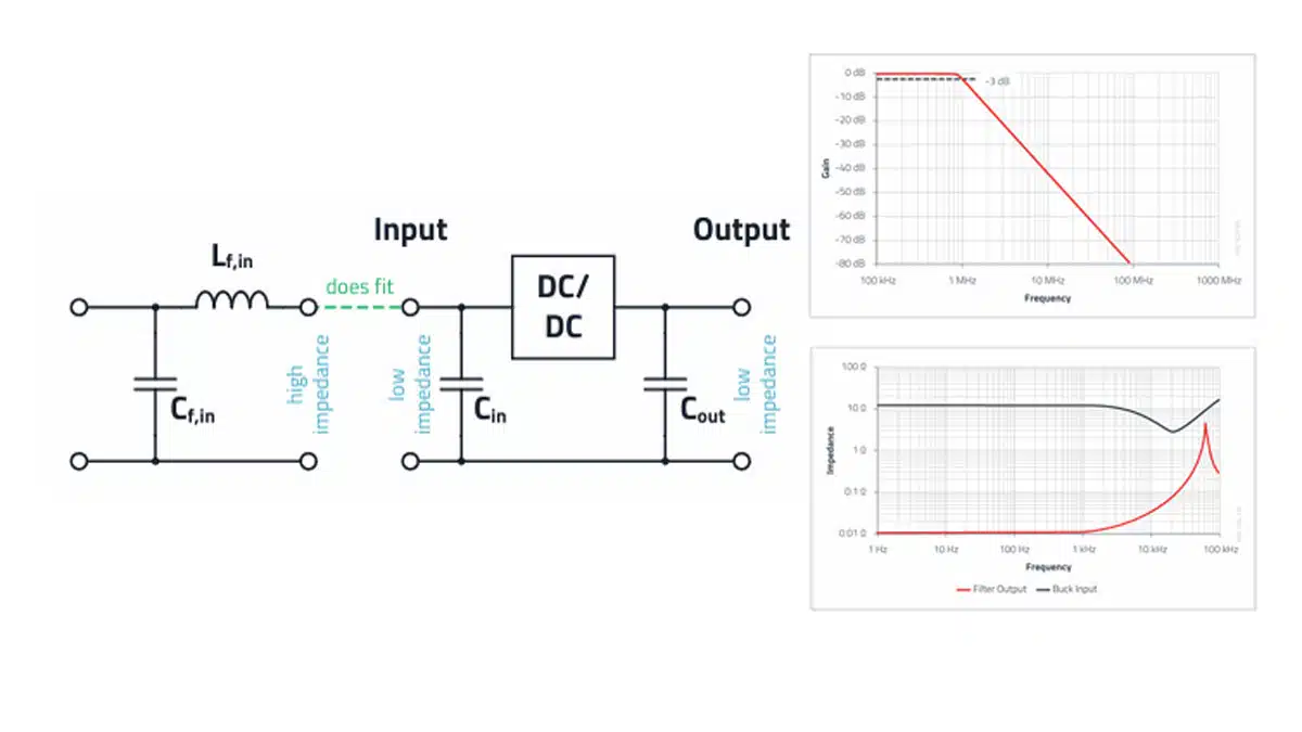
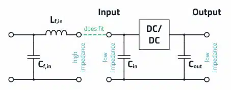
The LC input filter must be configured as in Figure 1., because the input capacitor of the converter represents a low impedance. In contrast, the filter inductor has a high impedance. Together with the filter capacitor, this forms an LC low-pass filter from the viewpoint of the DC/DC converter.
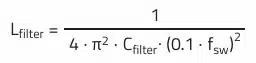
As mentioned in the “Selection of Capacitors for DC/DC Converters” it is useful to orientate the filter design primarily to the converter’s switching frequency. If this frequency is reduced by the filter in the spectrum, e.g., by 30 dB, the next harmonics of this fundamental frequency are naturally reduced in turn. This is easy to show with the help of Thomson’s oscillation equation:
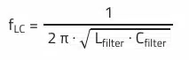
This equation describes the –3 dB point of the filter cut-off frequency. From this point onward, the LC filter theoretically provides 40 dB of attenuation per frequency decade.
If this frequency point is now set to 1/10 of the switching frequency (for example at 1 MHz, this is 100 kHz), then in the ideal case 40 dB filter attenuation is obtained. Sample calculations are given in the following chapters. A good compromise between component size, cost, and the parasitic characteristics of the filter elements for many DC/DC converters results in:
Filter inductor: From 0.47 µH to 22 µH
Filter capacitor: From 1 µF to 100 µF
Input filter topologies and component choices
The simplest and most widely used input filter is a single LC low‑pass as shown in Figure 1. In applications with more demanding conducted EMI limits or very noisy input environments, a π‑filter (C‑L‑C) or a multi‑stage filter is often used instead of, or in addition to, the basic LC filter. Adding extra capacitors improves high‑frequency attenuation, but it also changes the damping and inrush behavior, so the resulting network must still satisfy the input stability criteria discussed below.
This progression from a single LC stage to more elaborate multi-stage networks tracks closely with power level and noise environment. Our Power Converter dossier’s EMI/filter technology mapping finds that simple single-stage filters with modest X/Y capacitors are usually sufficient for adapters and low-power DC/DC applications, whereas multi-stage filters with additional choke stages and coordinated X/Y networks become necessary as power scales into the kilowatt range — a filter tuned for a 65 W adapter does not scale directly to a 10 kW system. Source: Passive Components for Power Converters Dossier, Passive Components Blog.
From a noise perspective, it is useful to distinguish between differential‑mode and common‑mode filtering. The LC and π networks discussed here primarily provide differential‑mode attenuation between the positive and negative DC lines. In isolated converter applications, a common‑mode choke and Y‑capacitors to chassis or protective earth are often added on the input side to suppress common‑mode noise; those measures complement the differential‑mode input filter and are covered in more detail in the EMC filter articles and webinars referenced at the end of this post.
The choice of component technology strongly influences filter performance. Multilayer ceramic capacitors (MLCCs) offer very low ESR and ESL and therefore excellent high‑frequency attenuation, but their very low losses tend to increase the quality factor of resonances and may require additional damping. Film capacitors provide stable capacitance over temperature and bias with moderate ESR and excellent ripple current capability, at the expense of larger size. Aluminum electrolytic capacitors bring higher ESR and higher capacitance values, which are useful for damping and energy buffering at lower frequencies, but they are less effective at very high frequencies and require attention to ripple current and lifetime.
The same trade‑offs apply to inductors. For input filters, shielded inductors are preferred when the component must be placed close to the converter or sensitive circuitry, because the closed magnetic path reduces stray field coupling to nearby traces. Core material and saturation current rating must be selected so that the inductor remains within its linear range over the full load and transient current profile of the DC/DC converter. Lower inductance values are generally beneficial for keeping DC resistance and the filter quality factor low, but they must still provide the required attenuation at the chosen cut‑off frequency.
| Component type | Strengths (for input filters) | Limitations / notes |
|---|---|---|
| MLCC capacitor | Very low ESR/ESL, excellent HF attenuation, compact size | Can create high‑Q resonances, capacitance reduction with DC bias, limited bulk energy storage |
| Film capacitor | Stable capacitance, good ripple current, moderate ESR helpful for damping | Larger volume, typically higher cost per µF |
| Aluminum electrolytic capacitor | High capacitance, ESR useful for damping, good for low‑frequency energy storage | Limited HF performance, finite lifetime, needs ripple current and temperature checks |
| Shielded inductor | Reduced stray field, less coupling into nearby traces, compact | Slightly higher cost and loss compared to unshielded types |
| Unshielded inductor | Lower cost and often lower DC resistance | Stronger radiated field, risk of noise coupling if placed close to sensitive nodes |
The inductance values of the filter inductors should be selected as low as possible to obtain a small DC resistance for a given component size, as well as not to compromise the stability of the DC/DC converter. A shielded filter inductor can be beneficial if it is placed very close to the DC/DC converter, as this reduces magnetic interference coupling.
Generally, it is beneficial to freely select the value of the filter capacitor and then use the formula below to determine the inductance value of the filter inductor:
Input stability criteria
If a filter is placed in front of a DC/DC converter, in practice this can lead to undesirable effects under certain circumstances:
• Deeper voltage dip and longer output voltage overshoot of the converter with a load step
• Pronounced oscillation of the voltage at the converter input
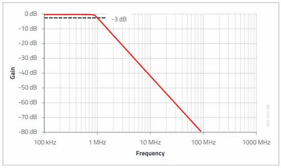
The reason for such effects is that the resulting impedance of the LFilter – Cin resonant circuit at the DC/DC converter input is too high. A converter with a filter is considered stable if the output impedance of the filter is significantly lower than the input impedance of the DC/DC converter over a certain frequency range in which the control loop is active.
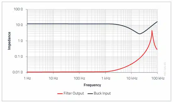
The example in Figure 3. shows that the red curve comes very close to the black curve in a certain frequency range. Here the filter inductance resonates with the input capacitor of the DC/DC converter (not with the filter capacitor, as is often wrongly described!). As these are high Q components in practice, this pronounced impedance rise occurs at the resulting cut-off frequency of Lfilter and Cin.
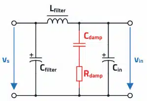
To reduce Q, and thus also the impedance rise of the resulting resonant circuit, it is usual to connect an attenuation capacitor Cdamp (possibly plus an external resistor) in parallel to the input capacitor. This capacitor should have a capacitance at least 3 to 4 times greater than the input capacitor and a dissipation factor as high as possible (e.g., aluminum electrolytic capacitors with high ESR).
In addition to the ESR, a low-inductance external SMT resistor Rdamp should also be used. In both cases, the maximum possible power loss of the components must be considered. In the capacitor branch, a purely ohmic loss resistance is required in any case to reduce the quality factor. The specification of 3 to 4 times the capacitance is justified by the fact that the reactance of the attenuating capacitor Cdamp must be lower than the ohmic attenuation resistance in the case of the undesired rise in the cut-off frequency (usually below 10 kHz), so that the attenuating capacitor can be effective.
It is desirable that the quality factor Q of this undesirable resonant circuit is in the range of 0.5 to 0.8. A quality factor in this range ensures a resonant circuit that is neither over-attenuated nor under-attenuated and prevents the undesirable impedance rise at the cut off frequency, which could violate the stability criterion.
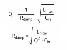
The equation above can be used to determine the required ohmic part Rdamp in the resonant circuit for a desired quality factor Q = 0.5…0.8. This can be the frequency dependent ESR of the attenuation capacitor, or an external resistor. The formula shows that the lowest possible filter inductance is advantageous, as the quality factor Q therefore does not become too high.
Interaction with the source and system requirements
The input filter does not operate in isolation; its behavior depends strongly on the impedance and dynamics of the upstream source. A laboratory power supply with fast current limiting, a long cable harness, an upstream DC bus, or a battery pack all present different source impedance profiles, which modify the effective resonance frequencies and damping of the input network. When the source impedance is high or poorly controlled, the LC filter can interact with it to produce deeper voltage dips or prolonged ringing unless sufficient damping is provided at the converter input.
Large input and damping capacitors also influence inrush current and startup behavior. At power‑on or hot‑plug events, the instantaneous charging of these capacitors can draw significant current from the source, potentially triggering protection or causing voltage droops on shared buses. In such cases, inrush limiting measures such as NTC thermistors, dedicated inrush controllers, or controlled startup sequences of the converters may be required in addition to the filter.
In automotive and industrial applications, the input filter is often combined with transient and surge protection components. TVS diodes, fuses, and surge absorbers are typically placed at the very input to handle load dump, voltage spikes and ISO 7637‑type pulses, with the LC input filter following them to clean up steady‑state ripple and conducted EMI. Coordinating the ratings and energy handling of these elements with the filter capacitor and inductor values is essential to ensure both EMC compliance and robustness over the full operating profile.
Practical implementation and verification
PCB layout has a decisive impact on the effectiveness of the input filter. The high‑di/dt loop formed by the input capacitor, the filter inductor and the converter input pins should be as small and compact as possible, with wide, short traces or planes to minimize stray inductance. The filter inductor should be placed close to the converter input, and the return current path should follow a tight, direct route to avoid coupling the noisy switching node into the input filter or sensitive signal traces.
Parasitic inductances and capacitances limit the real‑world attenuation of the filter, especially at higher frequencies. The ESL of the filter capacitor and the inductance of PCB traces and vias reduce the effective impedance of the capacitor at high frequency, which flattens the attenuation curve compared to the ideal 40 dB/decade behavior. Using several capacitors in parallel, with different values and package sizes, and placing them very close to the inductor and converter pins helps to extend the useful attenuation range and reduce resonances.
Filter performance and stability should be verified in the lab rather than relying on calculations alone. A LISN combined with a spectrum analyzer or EMC receiver allows measurement of conducted emissions against the relevant CISPR or EN limits. Differential probes can be used to measure input ripple voltage and current at the converter pins, while impedance analysis or frequency‑response measurements (Bode plots) can confirm that the filter output impedance remains below the converter input impedance over the control‑loop bandwidth. These measurements provide direct feedback to fine‑tune component values and damping before committing to volume production.
EMC Filter Designer
With the help of a new module, the “EMC Filter Designer” as part of the REDEXPERT tool, the developer can now select the required filter components quickly and easily.
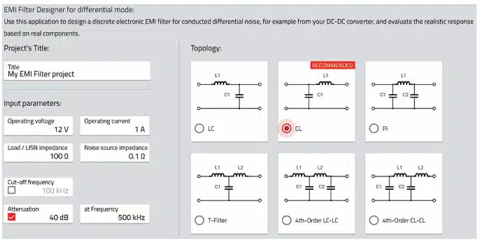
The impedance of the interference source is determined from the input capacitor of the DC/DC converter, therefore a reference value of 0.1 Ω can be assumed here. As this is a pure differential mode filter design, 100 Ω should be entered for the LISN impedance. Based on these impedance conditions and the desired attenuation, the tool suggests a suitable filter topology. As an alternative to attenuation, a filter cut-off frequency (usually 1/10 of the switching frequency) can also be entered as a selection criterion.
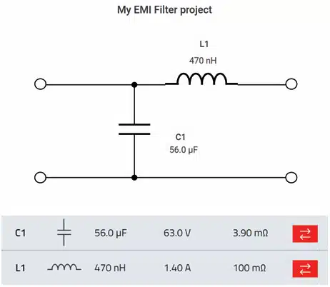
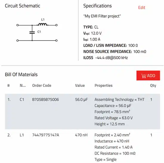
The components in Figure 6. are selected based on the current and voltage specifications from the first input page but can also be changed at any time. Manual selection of components is accomplished by selecting the double arrow symbol on the right. This brings up a list of suitable articles or the user may add specific parts. The resulting insertion loss, input and output impedance are plotted immediately. The summary tab compiles the BOM and plots into one
document as shown in Figure 7.
further reference link: EMC Filters Explained – from Component to Design; WE Webinar
Key terms used
- Cin – Effective input capacitance of the DC/DC converter at its input pins.
- Cdamp – Additional damping capacitor connected in parallel to Cin to reduce resonance Q.
- Rdamp – Loss element (ESR or external resistor) associated with Cdamp that provides damping.
- Q – Quality factor of a resonant circuit; high Q means low damping and pronounced impedance peaks.
- fC – Filter cut‑off frequency, typically chosen around one tenth of the switching frequency.
- LISN – Line Impedance Stabilization Network, used in EMC testing to define the source impedance and measure conducted emissions.
Source and further reading
The core material in this article is adapted, with permission, from Würth Elektronik’s DC/DC Converter Handbook, with additional commentary, examples and FAQ provided by the Passive Components Blog. For deeper dives into EMC filter design and measurement, readers are encouraged to consult the referenced WE webinars and the related knowledge‑base articles on capacitors, inductors, EMC filters and circuit protection.
Passive Components for Power Converters Dossier – cross-topology EMI/filter technology mapping (single-stage vs. multi-stage) and derating guidelines for filter inductors and capacitors
FAQ: Input Filters for DC/DC Converters
DC/DC converters, particularly buck converters, require input filters to reduce switching noise and electromagnetic interference (EMI). Even with properly designed input capacitors, an additional LC input filter providing 30 dB or more attenuation is necessary in most applications to ensure stable operation and meet EMC requirements.
Input filters typically use an LC low-pass configuration consisting of a filter inductor (0.47 µH to 22 µH) and a filter capacitor (1 µF to 100 µF). The inductor should have low DC resistance and may be shielded if placed close to the converter to reduce magnetic interference coupling.
The filter cut-off frequency should typically be set to 1/10 of the converter’s switching frequency using Thomson’s oscillation equation. For example, with a 1 MHz switching frequency, the cut-off frequency should be approximately 100 kHz to achieve ideal 40 dB attenuation.
A converter with input filter is considered stable when the output impedance of the filter remains significantly lower than the input impedance of the DC/DC converter across the frequency range where the control loop operates. Violating this criterion can cause deeper voltage dips, longer output voltage overshoots, and pronounced input voltage oscillations.
To reduce the quality factor (Q) and prevent impedance rise at resonance, connect a damping capacitor (Cdamp) with 3-4 times greater capacitance than the input capacitor in parallel. Use aluminum electrolytic capacitors with high ESR or add an external SMT resistor (Rdamp) to achieve a Q factor between 0.5 and 0.8.
The EMC Filter Designer is a Würth Elektronik tool module that helps developers select appropriate filter components quickly. It suggests suitable filter topologies based on input parameters like source impedance, LISN impedance, desired attenuation, and switching frequency, then generates a complete BOM with insertion loss and impedance plots.
A π‑filter (C‑L‑C) is useful when a single LC stage cannot provide enough conducted EMI attenuation or when the source and load impedances vary widely over operating conditions. The extra capacitor stage improves high‑frequency attenuation and can help meet tight EMC limits, but it also increases inrush current and changes the damping, so the final design must still be checked against the input stability criterion.
Several converters can share a common upstream input filter, especially when they operate from the same DC bus and in similar frequency ranges. However, the combined dynamic input impedance becomes more complex, and converters may interact through the shared filter, so verification of stability and conducted EMI with all converters operating is essential.
MLCCs are ideal for high‑frequency attenuation and small form‑factors, but their low ESR and DC bias effects must be considered when assessing damping and effective capacitance. Film capacitors provide stable, moderate‑loss behavior with good ripple performance, while aluminum electrolytic capacitors offer high capacitance and inherent ESR that is often beneficial for damping lower‑frequency resonances. In practice, combinations of these technologies are frequently used to cover a wide frequency range and meet lifetime and size requirements.
Common pitfalls include omitting damping components, placing the filter physically far from the converter input, under‑rating inductors for peak current, and relying on ideal calculations without verifying the impact of parasitics and the actual source impedance. Another frequent mistake is focusing solely on attenuation at the switching frequency while neglecting the impedance‑based stability criterion, which can lead to oscillations and poor transient behavior.
How to Design an Input Filter for DC/DC Converters
- Determine the Target Filter Cut-off Frequency
Set the filter cut-off frequency to approximately 1/10 of the DC/DC converter’s switching frequency. For example, if the switching frequency is 1 MHz, target a cut-off frequency of 100 kHz to achieve 40 dB attenuation at the fundamental frequency.
- Select the Filter Capacitor Value
Choose an appropriate filter capacitor value between 1 µF and 100 µF based on your application requirements. Consider the voltage rating, temperature characteristics, and available board space when selecting the capacitor.
- Calculate the Required Filter Inductor Value
Use Thomson’s oscillation equation to calculate the inductance value based on your chosen capacitor and target cut-off frequency. Select inductance values between 0.47 µH and 22 µH, prioritizing lower values to minimize DC resistance and component size.
- Configure the LC Filter Correctly
Place the filter inductor in series with the input, followed by the filter capacitor connected to ground. This configuration ensures the inductor presents high impedance while the capacitor provides low impedance, forming an effective LC low-pass filter from the converter’s perspective.
- Add Damping Components for Stability
Connect a damping capacitor (Cdamp) with 3-4 times the capacitance of the input capacitor in parallel to the converter’s input capacitor. Use aluminum electrolytic capacitors with high ESR or add an external SMT resistor to achieve a quality factor Q between 0.5 and 0.8, preventing undesired resonance.
- Verify Impedance Requirements
Ensure the output impedance of the filter remains significantly lower than the input impedance of the DC/DC converter across the control loop frequency range. Use impedance analysis tools or simulation to confirm the stability criterion is met.
- Use EMC Filter Designer Tools
Leverage tools like Würth Elektronik’s REDEXPERT EMC Filter Designer to automatically select optimal components. Enter your converter’s input capacitance (typically 0.1 Ω source impedance), LISN impedance (100 Ω for differential mode), desired attenuation, and switching frequency to receive component suggestions with complete BOM and performance plots.


