Passive Components Blog
No Result
View All Result
  • Home
  • NewsFilter
    • All
    • Aerospace & Defence
    • Antenna
    • Applications
    • Automotive
    • Capacitors
    • Circuit Protection Devices
    • electro-mechanical news
    • Filters
    • Fuses
    • Inductors
    • Industrial
    • Integrated Passives
    • inter-connect news
    • Market & Supply Chain
    • Market Insights
    • Medical
    • Modelling and Simulation
    • New Materials & Supply
    • New Technologies
    • Non-linear Passives
    • Oscillators
    • Passive Sensors News
    • Resistors
    • RF & Microwave
    • Telecommunication
    • Weekly Digest

    Samsung Introduced Low ESL 3-Terminal Reverse-Geometry MLCCs for High-Performance ADAS

    Würth Elektronik Presents New Bidirectional Digital Isolators

    Using Stress–Strain Curves to Diagnose Tantalum Powders for Capacitors

    Coilcraft Introduces SMT Current Sense Transformers for High‑Performance Power Electronics

    Samsung Launches Ultra-Compact 008004 High Q MLCC for Next-Generation RF Applications

    Nichicon Extends Rechargeable Batteries Temperature to Rival Supercapacitors

    Two‑capacitor paradox explained for engineers

    YAGEO Releases Compact RJ45 Connector for Multi‑Gigabit Ethernet

    Circuit Protection Technology Annual Dossier

    Trending Tags

    • Ripple Current
    • RF
    • Leakage Current
    • Tantalum vs Ceramic
    • Snubber
    • Low ESR
    • Feedthrough
    • Derating
    • Dielectric Constant
    • New Products
    • Market Reports
  • VideoFilter
    • All
    • Antenna videos
    • Capacitor videos
    • Circuit Protection Video
    • Filter videos
    • Fuse videos
    • Inductor videos
    • Inter-Connect Video
    • Non-linear passives videos
    • Oscillator videos
    • Passive sensors videos
    • Resistor videos

    Two‑capacitor paradox explained for engineers

    Capacitances of Nonlinear MLCCs: What Datasheets Don’t Tell You

    Tapped Inductor Buck Converter Fundamentals

    Planar vs Conventional Transformer: When it Make Sense

    Modeling Fringing Field Losses in Inductors & Transformers

    Why Power Inductors Use a Ferrite Core With an Air Gap

    Transformer-Based Power-Line Harvester Magnetic Design

    Thermal Modeling of Magnetics

    Standard vs Planar LLC transformers Comparison for Battery Chargers

    Trending Tags

    • Capacitors explained
    • Inductors explained
    • Resistors explained
    • Filters explained
    • Application Video Guidelines
    • EMC
    • New Products
    • Ripple Current
    • Simulation
    • Tantalum vs Ceramic
  • Knowledge Blog
  • DossiersNew
  • Suppliers
    • Who is Who
  • PCNS
    • PCNS 2025
    • PCNS 2023
    • PCNS 2021
    • PCNS 2019
    • PCNS 2017
  • Events
No Result
View All Result
Passive Components Blog
No Result
View All Result

IPC Class 2 vs Class 3 Solder Joints Requirements Explained

27.2.2025
Reading Time: 5 mins read
A A

In this post, inspired by the Samtec blog, we’ll briefly examine IPC-A-610 Class 2 and Class 3 J-lead and Gull Wing solder joints, along with their respective requirements.

In the manufacturing world there are standards for just about everything, and they all are typically there to ensure a product can perform as expected for the end application. Among these standards is IPC-A-610 covering solder joints for varying types of connector termination styles.

RelatedPosts

Samtec AcceleRate Slim ARC6 Cable Assemblies with New Signaling Options

Samtec ANSI/VITA 90 Connectors: Rugged Small Form Factor Standard

Coaxial Connectors and How to Connect with PCB

What is IPC-A-610

IPC-A-610 delves into the concept of “Acceptability of Electronic Assemblies,” and for the purpose of this blog, we will specifically focus on the requirements for J-Lead and Gull Wing solder connections. Considering the diverse applications that necessitate varying requirements, IPC has established different classes, each specifying the aesthetic characteristics of solder joints that must conform to those class specifications.

Class 2 

J-Lead Components

IPC-A-610 Class 2 is the standard requirement for J-lead component termination soldering. Class 2 products need extended reliability, but it’s not a critical requirement. We’ll cover some of the requirements below, but not all of them.

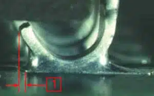
Class 2 allows the manufacturer more room for imperfections in the assembly, such as a larger toe offset (1) and side overhang (2), and a thinner end joint width (3) as shown in Figures 1 and 2 below. For side overhang, Class 2 states that the component lead may overhang the side of the pad (2), a maximum of 50% the width of the lead.

The end joint width (3) is the width of the solder joint at the most narrow point and must be a minimum of 50% of the lead width (4).

Figure 1. solder joint toe offset
Figure 2. solder joint side overhang, joint width and lead width

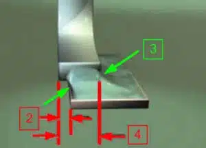
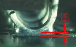
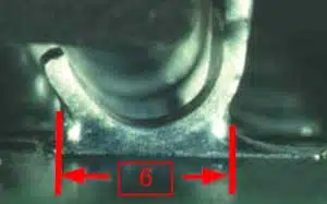
The solder thickness (5) between the lead and the pad landing is not specified, but a properly wetted fillet must be present. The side joint length (6) of the solder joint, at the narrowest point, must be at least 150% the width of the lead (4).

Figure 3. solder joint thickness
Figure 4. solder joint length

Class 2 is typically focused on a commercial type of product where continued performance and extended life is required, and an uninterrupted service of the product is desired but not mission critical. The normal environment (temperature and contamination) for this end user is not considered extreme.

Gull Wing Components

Because Class 2 provides the manufacturer a larger degree of imperfection in the solder joint, it is easier to manufacture at this level and often cheaper to produce. An example of this is the “pad offset” or the overhang of the contact from the pad. The Toe Overhang is defined in similar way as shown in Figure 1 for J-lead also for Gull Wing termination style, and is acceptable as long as it does not violate electrical clearance. This also means there is no requirement for a Toe Filet. The Side Overhang is shown in Figure 2., and Joint Width is also measured as is shown in (3) on the same figure.

Side Overhang (2), for Class 2, states a component lead may overhang the side of the land (contact pad) with a maximum of 50% the lead width(4), or 0.02 in. (0.5 mm), whichever is less. End Joint Width (3) is the width of the solder joint at the most narrow point. This width must be a minimum of 50% the width of the lead (4) . 

Side Joint Length (6) for a “long foot,” or a Lead Foot Length (5) that is equal to or greater than three lead widths (4), the Side Joint Length (6) must be a minimum of 3 (4) or 75% of (5); which ever is the longer of the two.

Class 3

J-Lead Components

Many high-reliability components and connectors can meet IPC-A-610 Class 3, which is usually required when a product must maintain high performance in extreme or harsh conditions. Military, aerospace, and medical applications typically require Class 3 products.

Class 3 imposes stricter inspection requirements for solder joints compared to Class 2. While the solder thickness (5) remains unchanged, the side joint length (6) is the same as Class 2. However, several other specifications have increased requirements.

For instance, the side overhang (2) and end joint width (3) are both tightened by 25% in both directions. The side overhang is limited to a maximum of 25% of the lead width (4), while the end joint thickness (3) is increased to a minimum of 75% of the lead width (4). Although this may not appear to be a significant increase, it does pose challenges in producing conforming products.

Gull Wing Components

Some requirements are similar in Class 2 and Class 3; such as the Solder Joint Length (6) and Toe Overhang (1). However, many of requirements are significantly more difficult to meet in a Class 3 solder joint.

End Joint Width (3) and Side Overhang (2), are both required to meet a more stringent specification. The End Joint (3) must be at least 75% of the lead width (4), and the Side Overhang (2) only affords the lead width (4) a maximum 25% of the lead width (4) or 0.02 in. (0.5 mm), whichever is less of overhang on the side of land.

Related

Source: Samtec

Recent Posts

Using Stress–Strain Curves to Diagnose Tantalum Powders for Capacitors

20.5.2026
5

Two‑capacitor paradox explained for engineers

18.5.2026
46

YAGEO Releases Compact RJ45 Connector for Multi‑Gigabit Ethernet

18.5.2026
16

ESA SPCD 26 Registration Open

15.5.2026
24

Capacitances of Nonlinear MLCCs: What Datasheets Don’t Tell You

14.5.2026
87

How a Digital Structural Twin Can Predict Tantalum Capacitor Reliability

14.5.2026
64

Binder Hybrid Connector Simplifies One Cable Automation

13.5.2026
21

Tapped Inductor Buck Converter Fundamentals

13.5.2026
43

Molecular Memristor Shows Record 145 kH Emergent Inductance

12.5.2026
47

Upcoming Events

Jun 2
16:00 - 17:00 CEST

Calculation, Simulation and Measurement of 800V EMC Filters

Jun 16
16:00 - 17:00 CEST

EMC with EMC – EMC‑compliant design with electromechanical connectors

View Calendar

Popular Posts

  • Buck Converter Design and Calculation

    0 shares
    Share 0 Tweet 0
  • Boost Converter Design and Calculation

    0 shares
    Share 0 Tweet 0
  • Flyback Converter Design and Calculation

    0 shares
    Share 0 Tweet 0
  • LLC Resonant Converter Design and Calculation

    0 shares
    Share 0 Tweet 0
  • MLCC and Ceramic Capacitors

    0 shares
    Share 0 Tweet 0
  • Capacitor Charging and Discharging

    0 shares
    Share 0 Tweet 0
  • What Electronics Engineer Needs to Know About Passive Low Pass Filters

    0 shares
    Share 0 Tweet 0
  • Dual Active Bridge (DAB) Topology

    0 shares
    Share 0 Tweet 0
  • Ripple Current and its Effects on the Performance of Capacitors

    3 shares
    Share 3 Tweet 0
  • Samsung Electro-Mechanics Releases High-Capacitance MLCCs for AI Server Applications

    0 shares
    Share 0 Tweet 0

Newsletter Subscription


Passive Components Blog

© EPCI - Leading Passive Components Educational and Information Site

  • Home
  • Privacy Policy
  • EPCI Membership & Advertisement
  • About

No Result
View All Result
  • Home
  • Knowledge Blog
  • PCNS

© EPCI - Leading Passive Components Educational and Information Site

This website uses cookies. By continuing to use this website you are giving consent to cookies being used. Visit our Privacy and Cookie Policy.
Go to mobile version