


Dr. Vladimir Azbel, an independent consultant on tantalum capacitors, analyzes structural changes in tantalum anodes of chip capacitors during long-term reverse-bias stress (RBS) testing.
These changes are assessed using mechanical characteristics as indicators of the final structural state. Dr. Vladimir Azbel aims to establish a link between these structural changes, the final leakage current (DCL) level, and anode design of tantalum capacitors.
Key Takeaways
- Mechanical testing reveals accumulated structural degradation beyond electrical observables.
- Post-test mechanical characterization captures irreversible structural evolution in the Ta–IF–amorphous Ta₂O₅ system that remains hidden to continuous electrical monitoring based on leakage current thresholds.
- Irreversible deformation localization governs long-term reverse-bias stability.
- The Mechanical Drift Index (MDI), dominated by the strain-hardening parameter k₂, identifies loss of plastic accommodation in the interface and neck regions as the key precursor of structurally irreversible degradation, enabling design-dependent ranking of reverse-bias robustness.
1. Introduction
Despite decades of investigation, there is still no consensus regarding the dominant conduction mechanisms and degradation pathways in tantalum capacitors under reverse-bias conditions. Proposed models invoke oxygen- or hydrogen-related diffusion, microcrack-assisted current localization, interface-controlled rectification, and electronic transport through traps; however, none of these approaches provides a reliable predictor of long-term DCL evolution across different anode designs and production lots.
In contrast to electrical parameters such as leakage current or capacitance, which are monitored continuously during testing and reflect the instantaneous functional state of the device, mechanical characteristics of the anode are determined after test completion and capture the cumulative structural changes accumulated over the entire exposure period. Accordingly, the mechanical response reflects the final energetic and stress state formed in the composite anode system during prolonged electrical and climatic stressing.
In the present work, the tantalum anode is treated as a composite system consisting of the metallic tantalum framework, the interface zone (IF), and the amorphous dielectric film (Ta–IF–amorphous Ta₂O₅). This representation enables analysis of degradation not through instantaneous electrical manifestations, but through the resulting structural state of the system formed during long-term exposure.
Unlike earlier studies, where mechanical characteristics were primarily employed as manufacturing-stage acceptance criteria, this work applies post-test mechanical characterization to analyze the final structural state of anodes after long-term reverse-bias testing. The analysis focuses on the relative drift of stress–strain curve parameters with respect to a reference state, rather than on their absolute values, enabling identification of differences in structural stability among anode designs and localization of the most vulnerable structural elements responsible for the observed leakage current behavior.
Under the test conditions considered in this work, the applied temperatures, atmospheres, and electrical stress levels are insufficient to induce changes in anode constituent volume fractions or macroscopic growth of the dielectric film. The observed changes in mechanical characteristics are therefore interpreted as manifestations of internal stress redistribution and defect accumulation within an already formed Ta–IF–amorphous Ta₂O₅ structure, rather than as a result of geometric or compositional modification.
Within this framework, degradation of the tantalum anode is regarded as an evolution of the energetic and stress state of the composite system. The total energetic contribution of external factors remains well below the Ta–O bond rupture energy, excluding chemical destruction of the dielectric and confining structural evolution to stress redistribution and defect development in the interface zone and adjacent porous neck regions.
Mechanical characteristics are thus employed as a sensitive integral response of the anode structure, while electrical parameters—most notably leakage current—are treated as secondary manifestations of accumulated structural changes that become observable only upon reaching specific energetic and structural thresholds.
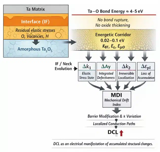
All structural changes occur within an energetic corridor well below the Ta–O bond rupture energy, resulting in the redistribution of stresses and defects rather than geometric modification of the dielectric.
2. Experimental Section
2.1. Capacitor types and reverse-bias stress conditions
Three types of tantalum chip capacitors with identical nominal ratings (10 µF, 25 V) were investigated. The capacitor types differed in anode design and characteristic neck size of the porous structure:
- MC1 (293D) — molded case, minimum neck size;
- CC1 (194D) — conformal coated, intermediate neck size;
- CWR (CWR06) — conformal coated, increased neck size.
Samples per group and type subjected to the testing:
| Group | type | QTY |
| 1 reference | CC1 /194D | 5 |
| CC2 /CWR | 5 | |
| MC /293D | 5 | |
| 2 Air,3000h,75°C | CC1 /194D | 7 |
| CC2 /CWR | 7 | |
| MC /293D | 6 | |
| 3 Vacuum,3000h./75°C | CC1 /194D | 5 |
| CC2 /CWR | 5 | |
| MC /293D | 5 | |
| 4 3000hr RBS at RT | CC2 /CWR | 13 |
| MC /293D | 7 | |
| 5 Vacuum,2500h./85°C | CC1 /194D | 13 |
| CC2 /CWR | 14 | |
| MC /293D | 10 | |
| 6 1000hr RBS at 20C85%RH | CC1 / 194D | 13 |
The electrical reverse-bias leakage current data used for comparison in this work were obtained on capacitor samples supplied by NASA and previously reported in independent long-term reliability studies [1,2]. These data are used here as a reference framework for correlating electrical behavior with post-test mechanical characterization.
All capacitor batches were subjected to reverse-bias stress (RBS = 5 V) under the following environmental and thermal conditions:
- Reference — initial state;
- Air, 75 °C, 3000 h;
- Vacuum, 75 °C, 3000 h;
- Air, 22 °C, 7% RH, 3000 h;
- Vacuum, 85 °C, 2500 h.
After completion of testing, the capacitors underwent a stripping procedure to extract the tantalum anodes, which were subsequently used for mechanical testing.
2.2. Mechanical testing and analysis approach
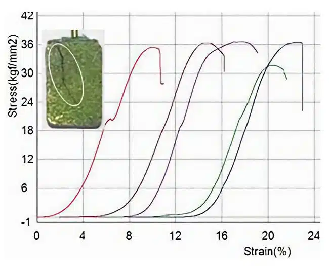
For each extracted anode, compression stress–strain curves were recorded. The following parameters were extracted:
- Ay — yield stress;
- Au — ultimate strength;
- εel — elastic strain;
- εpl — plastic strain;
- k₁ — slope of the initial elastic segment of the curve;
- k₂ — slope of the plastic deformation (strain-hardening) segment.
Subsequent analysis was performed using relative changes (Δ%), normalized to the corresponding Reference state. A deliberate sign convention was adopted; whereby negative values indicate an increase of a parameter relative to the Reference state. This convention emphasizes the presence of pre-existing residual tensile stresses in the anode structure, which are compensated during compression mechanical testing.
3. Results and Discussion
3.1. Mechanical characteristics as a tool for structural response decomposition
In the present work, mechanical parameters are used as a means of decomposing structural changes in tantalum anodes induced by prolonged electrical and climatic stressing, rather than as a set of independent material constants.
Considering the composite nature of the anode (Ta–IF–amorphous Ta₂O₅) and the localization of maximum residual stresses within the interface zone, variations in stress–strain (SS) curve parameters are interpreted primarily as indicators of structural evolution in the interface region and the adjacent porous neck areas. This interpretation is consistent with earlier treatments of the anode as a composite system, in which global mechanical parameters represent the combined response of multiple structural constituents rather than a single degradation mechanism [3]. In this context, monotonic changes in yield or ultimate strength (Ay, Au) mainly reflect overall structural stiffening and therefore lack selectivity with respect to specific degradation pathways.
Within this framework, individual mechanical parameters carry distinct diagnostic significance:
- Δk₁ reflects the presence and magnitude of internal elastic stresses associated with changes in the interface zone and the lattice state of the tantalum matrix. This parameter is sensitive to the overall stress state of the system, largely independent of the physical origin of the stresses (oxygen- or hydrogen-related effects, charge accumulation, or thermomechanical mismatch).
- ΔAy is an integral but non-specific parameter influenced by multiple types of structural changes and defects. An increase in Ay indicates enhanced resistance to the onset of plastic deformation; however, taken alone, it does not uniquely identify the underlying degradation mechanism and requires correlation with other parameters.
- Δk₂ reflects irreversible structural changes and localization of plastic deformation in the most vulnerable regions of the anode, primarily within the interface zone and the porous necks. This parameter provides the most sensitive indication of loss of plastic accommodation capability.
The ability of the structure to accommodate plastic deformation—and the loss of this ability—plays a central role in determining the mechanical response of the anode under prolonged electrical and climatic stressing. In this context, the parameters Ay and εpl serve a supporting and interpretative role, indicating how accumulated defects and internal stresses modify resistance to deformation onset and the remaining capacity for plastic accommodation.
The separation between elastic stress accumulation and irreversible structural evolution adopted in this work is phenomenological and based solely on decomposition of the mechanical response, without invoking defect-specific assumptions. Accordingly, combined analysis of variations in k₁, Ay, and k₂ enables discrimination between fundamentally different regimes of anode structural evolution:
- dominant accumulation of elastic stresses;
- irreversible degradation of the interface zone;
- transition to a non-accommodative, brittle structural state.
It is important to emphasize that elastic stresses localized in the interface zone and transmitted to the amorphous Ta₂O₅ film may significantly affect dielectric properties without any change in oxide thickness. In particular, tensile stresses in the amorphous oxide can modify local polarizability and effective dielectric constant. Such changes do not necessarily produce measurable capacitance variation, but may substantially reduce local barrier properties and thereby increase the risk of leakage current (DCL) growth.
3.2. Individual mechanical response of anodes (MC1, CC1, CWR)
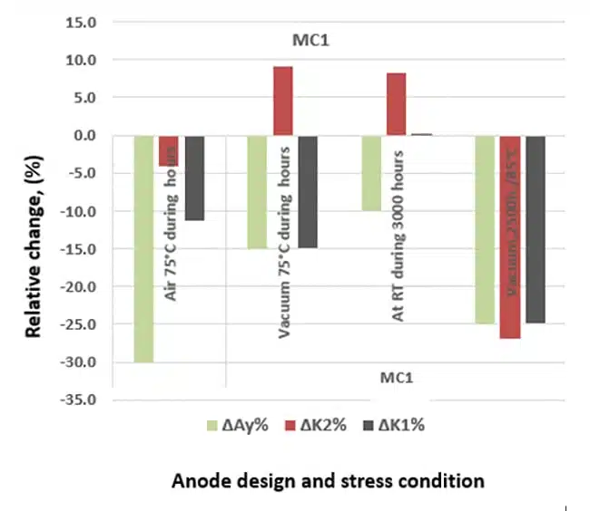
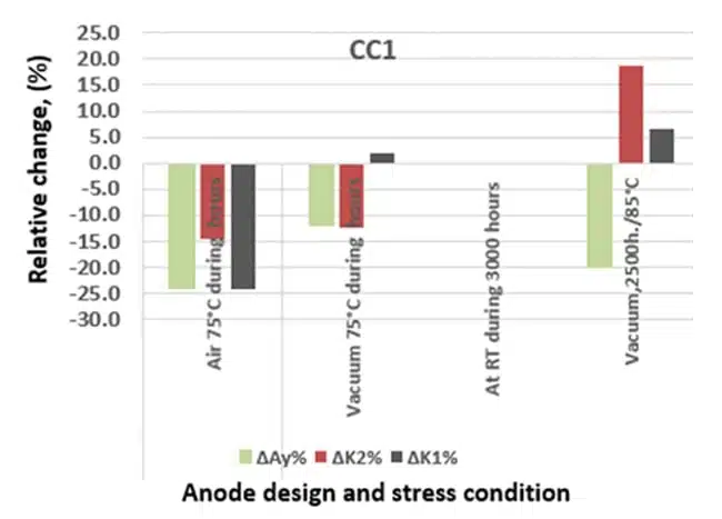
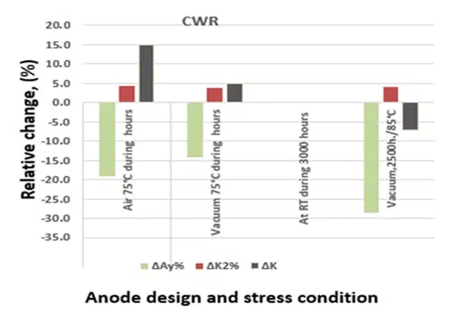
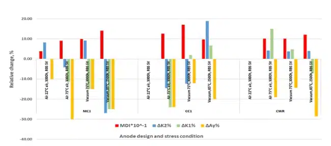
For each anode type (MC1, CC1, and CWR), separate plots of relative changes in mechanical parameters ΔAy%, Δk₁%, and Δk₂% were constructed under the different stress conditions
(see Appendix A, Figures A1–A3).
These plots constitute an individual mechanical “degradation passport” for each anode design and enable identification of the dominant structural evolution mechanisms—whether governed primarily by elastic stress accumulation or by the development of irreversible structural damage—under specific test conditions.
Analysis of the individual mechanical responses shows that, even under identical external stress conditions, the evolution of mechanical parameters differs markedly among anode designs. This behavior reflects different degrees of interface-zone involvement and different effective volumes of the porous neck participating in stress redistribution and defect accumulation.
Thus, the individual mechanical responses capture not only the effect of the applied stress conditions, but also the intrinsic structural sensitivity of each anode design to a given type of electrical and environmental loading.
3.3. Comparative analysis and integral representation of the mechanical response
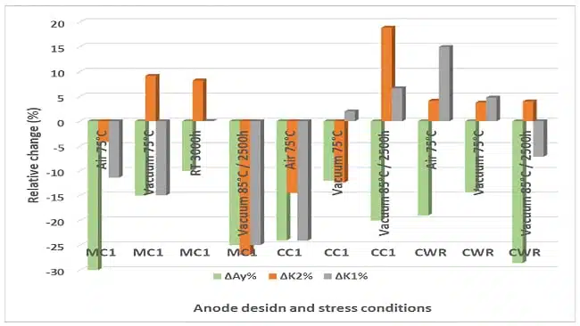
To generalize the results and enable direct comparison of anodes with different designs, a consolidated triple-parameter plot of the relative mechanical changes ΔAy, Δk₁, and Δk₂ for MC1, CC1, and CWR anodes is used in the main text. The data are presented on a common scale and under identical stress conditions (Figure 2).
Alternative representations based on relative changes in elastic and plastic strain (εel and εpl) were considered but are not used in the main analysis. Although these parameters reflect the final mechanical response of the anode, their evolution is dominated by global deformation and geometry-dependent effects that differ substantially among anode designs. As a result, εel and εpl do not reveal a common structural response under identical stress conditions.
In contrast, the relative drift of the stress–strain curve slopes (k₁ and k₂) is localized to the interface zone and porous neck regions and therefore provides a more sensitive and design-robust indicator of stress redistribution and irreversible structural evolution. For this reason, the k₁–k₂–Ay representation is adopted as the primary diagnostic framework in this work.
Within this framework, the mechanical response of the anodes can be interpreted as the combined effect of three fundamentally different contributions:
- (i) accumulation of elastic stresses,
- (ii) changes in the integral resistance to the onset of plastic deformation,
- (iii) development of irreversible structural changes localized in the interface zone and porous neck regions.
Analysis of Figure 2 shows that:
- under identical stress conditions, the mechanical response is governed primarily by anode design rather than by the nominal electrical rating of the capacitor;
- MC1 anodes exhibit the most pronounced changes in Δk₂ and ΔAy, indicating an early transition of the interface zone toward irreversible structural degradation;
- CC1 anodes display intermediate behavior, characterized by partial preservation of plastic accommodation;
- CWR anodes show minimal changes in all three parameters and the highest ability of the structure to redistribute internal stresses.
These results confirm that neck geometry and the structural state of the interface zone are the dominant factors controlling the mechanical stability of the anode. The triple-parameter analysis (ΔAy–Δk₁–Δk₂) enables clear separation of stress-dominated and defect-dominated degradation regimes without reliance on electrical failure criteria.
At the same time, the monotonic increase of yield stress (Ay) observed across all anode designs and test conditions indicates that Ay alone lacks sufficient discriminative power with respect to degradation pathways. In contrast, parameters associated with the localization of plastic deformation (k₂, supported by εpl) exhibit selective sensitivity to irreversible structural changes. This observation motivates the introduction of derived integral metrics that emphasize irreversible deformation localization rather than primary mechanical parameters.
However, the triple mechanical representation by itself does not provide a quantitative measure of irreversibility and does not allow direct correlation of mechanical drift with the final leakage current level. This limitation motivates the introduction of an integral mechanical metric, discussed in the following section.
3.4. Mechanical drift as a predictor of the final DCL level
Mechanical characteristics measured after completion of the 3000 h tests reflect the final structural state of the anode formed during long-term aging. Unlike leakage current (DCL), which is continuously monitored during testing and used as a threshold-based indicator of degradation, mechanical parameters are determined only after test completion and therefore represent an integral structural “memory” accumulated over the entire exposure period.
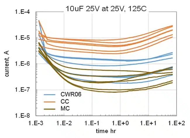
Figure 3 shows the time evolution of leakage current under reverse-bias stress for MC1, CC1, and CWR capacitors subjected to different thermal and environmental conditions.
The electrical reverse-bias leakage current data discussed in this section were not reproduced within the scope of the present work. Instead, previously published long-term reverse-bias test results obtained on capacitor samples supplied by NASA were used as a reference framework for correlating electrical behavior with post-test mechanical characterization [Refs. 1,2 ]. The present work does not re-evaluate the electrical failure statistics reported in these studies.
Although DCL monitoring clearly identifies the onset and progression of electrical degradation, the final DCL level alone does not distinguish between degradation pathways dominated by elastic stress accumulation and those governed by irreversible structural damage.
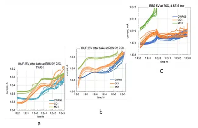
In contrast to electrical monitoring, post-test mechanical characterization enables discrimination between degradation regimes dominated by elastic stress transfer and those controlled by irreversible damage of the anode skeleton.
To enable a quantitative comparison of mechanical drift across different anode designs and stress conditions, an integral parameter—the Mechanical Drift Index (MDI)—was introduced. The MDI is not intended as a universal damage parameter, but as a pragmatic integral indicator designed to emphasize irreversible deformation localization while suppressing purely elastic contributions selectively. The MDI combines normalized changes in key stress–strain parameters:
- increase in yield stress (Ay),
- reduction in plastic strain (εpl),
- change in the strain-hardening parameter (k₂), reflecting localization of plastic deformation.
Table 2 summarizes the normalized mechanical parameters (Ay/Ay₀, εpl/εpl₀, k₂/k₂₀) together with the corresponding MDI values for MC1, CC1, and CWR anodes under different reverse-bias stress conditions.
| Anode | Condition | Ay/Ay₀ | εpl/εpl₀ | K2/K2₀ | MDI |
| MC1 | Air 75°C | 1.17 | 0.58 | 1.44 | 0.98 |
| MC1 | Vacuum 75°C | 1.12 | 0.60 | 1.23 | 0.83 |
| MC1 | RT 3000 h | 1.22 | 0.31 | 0.58 | 0.22 |
| MC1 | Vacuum 2500 h / 85°C | 1.12 | 0.71 | 1.82 | 1.45 |
| CC1 | Air 75°C | 1.24 | 0.71 | 1.57 | 1.39 |
| CC1 | Vacuum 75°C | 1.12 | 0.86 | 1.30 | 1.25 |
| CC1 | Vacuum 2500 h / 85°C | 1.20 | 0.86 | 0.94 | 0.97 |
| CWR | Air 75°C | 1.40 | 0.55 | 0.90 | 0.69 |
| CWR | Vacuum 75°C | 1.12 | 0.87 | 0.95 | 0.93 |
| CWR | Vacuum 2500 h / 85°C | 1.16 | 0.76 | 1.22 | 1.09 |
Table 2. Normalized mechanical parameters and Mechanical Drift Index (MDI) for MC1, CC1, and CWR anodes under different reverse-bias stress conditions.
Analysis of Table 2 shows that the MDI is governed primarily by the relative change in k₂. This is not accidental: the k₂ parameter captures the onset of irreversible structural changes manifested as localization of plastic deformation in the interface zone and the porous neck regions. Importantly, k₂ does not specify the physical nature of the defects—whether oxygen-related, hydrogen-related, charge-induced, or thermomechanical—but rather indicates the loss of structural reversibility itself.
In contrast, changes in Ay and εpl play a supporting, modulatory role. These parameters reflect how accumulated defects and residual stresses influence resistance to deformation onset and the remaining capacity for plastic accommodation, but they do not independently discriminate between reversible and irreversible degradation pathways.
The MDI is intentionally constructed to underweight elastic stress–related contributions, which are primarily reflected by changes in k₁ and, to a lesser extent, Ay. Consequently, cases characterized by relatively low MDI values combined with pronounced changes in Δk₁ and/or ΔAy correspond to degradation regimes dominated by elastic stress transfer from the interface zone to the amorphous Ta₂O₅ film. In such regimes, DCL growth is driven predominantly by stress-induced modification of dielectric barrier properties rather than by permanent damage of the anode skeleton.
A characteristic signature of elastic-stress-dominated regimes is the absence of DCL saturation during testing. Unlike vacuum conditions, where leakage current typically approaches a plateau, tests performed in air often show a continuous increase in DCL with time. This behavior indicates that the system does not reach a stable energetic minimum but remains in a metastable, stress-loaded state.
The qualitative difference between air and vacuum conditions can be rationalized by considering atmosphere-assisted stabilization of stress and defect states in the interface zone. Under reverse bias, dipole reorientation in amorphous Ta₂O₅ generates internal elastic stresses. In a vacuum, the system tends to relax toward a quasi-equilibrium state via limited defect annihilation and micro-accommodation within the porous neck volume, which is consistent with DCL approaching a plateau. In air at elevated temperature (75–85 °C), the presence of reactive species and residual moisture can stabilize charged defects and interfacial states, slowing stress relaxation and maintaining the structure in a metastable, stress-loaded condition. As a result, DCL may continue to drift rather than saturate, even when the extent of irreversible skeleton damage (MDI) remains moderate.
At 75 °C, even low levels of ambient moisture may contribute to time-dependent drift by providing mobile species (e.g., hydrogen-related defects) that interact with the oxide/interface region. Such contributions are not claimed here as a uniquely proven mechanism for the tested lots; rather, they represent a physically plausible pathway consistent with the observed divergence between air and vacuum behavior and with the known sensitivity of amorphous oxides to defect and charge stabilization under bias at elevated temperature.
The interpretation of non-saturating DCL behavior as indicative of incomplete stress relaxation is therefore based on consistent trends observed in electrical and mechanical responses, rather than on direct measurement of internal stresses.
The temperature dependence of the divergence between air and vacuum conditions suggests that the underlying relaxation and stabilization processes are thermally activated; however, extraction of a reliable activation energy is beyond the scope of the present work.
Conversely, high MDI values indicate defect-dominated degradation pathways controlled by irreversible deformation localization (k₂-driven), which are associated with a substantially increased risk of long-term leakage current instability.
From an energetic perspective, the observed mechanical drift reflects energy redistribution within a narrow corridor well below the Ta–O bond rupture energy. Structural changes, therefore, remain localized in the interface zone and are transmitted to the amorphous Ta₂O₅ film primarily in the form of elastic stresses, affecting dielectric stability without geometric modification or thickness change of the oxide.
Comparison of the triple mechanical response plots (ΔAy, Δk₁, Δk₂; Figure 3) with the corresponding MDI values confirms that the triple-parameter representation identifies the mechanical regime of degradation, whereas the MDI selectively tracks irreversible structural evolution. High MDI values correspond to defect-dominated degradation, while low MDI combined with pronounced Δk₁ indicates stress-dominated regimes in which elastic stresses may significantly contribute to DCL growth despite limited irreversible damage.
3.5. Influence of Anode Design
Comparison of the results obtained for MC1, CC1, and CWR anodes demonstrates that anode design acts as an effective amplifier of degradation mechanisms by controlling both the degree of interface-zone involvement and the effective neck volume participating in structural evolution.
Under identical electrical and thermal stress conditions, anodes with different geometries exhibit fundamentally different mechanical responses:
• MC1 (minimum neck size) shows the largest mechanical drift and the highest MDI values, indicating an early onset of irreversible structural degradation;
• CC1 exhibits an intermediate response, characterized by partial preservation of plastic accommodation and moderate defect accumulation;
• CWR demonstrates the highest structural stability, owing to more uniform stress distribution and sustained ability for plastic accommodation.
This design-dependent hierarchy directly explains the experimentally observed trend in final leakage current levels and long-term stability:
MC1 > CC1 > CWR
Thus, characteristic neck geometry and the resulting stress distribution within the interface zone emerge as the dominant design-controlled factors governing both mechanical robustness and electrical reliability of tantalum capacitor anodes under prolonged reverse-bias stress.
3.6. What Mechanical Testing Reveals: Generalization and Practical Interpretation
The absence of a universal electrical or physicochemical indicator of reverse-bias degradation motivates the use of post-test mechanical characterization as an integral probe of accumulated structural evolution. Mechanical parameters are sensitive to redistribution of internal stresses and defect localization in the interface zone and porous neck regions, regardless of whether the underlying driving mechanism involves oxygen diffusion, hydrogen-related effects, or charge-induced stress.
The analysis presented in this work demonstrates that mechanical testing of tantalum anodes provides information fundamentally different from that obtained by electrical measurements and enables interpretation of leakage current degradation at the level of the physical structural state of the anode. While electrical parameters reflect the instantaneous functional state of the device during testing, mechanical characteristics capture the final structural state formed over the entire period of electrical and climatic exposure.
Analysis of the relative drift of stress–strain curve parameters shows that different mechanical parameters carry distinct diagnostic significance:
• the relative change of the strain-hardening parameter k₂ captures the onset of irreversible structural changes associated with localization of plastic deformation in the interface zone and porous neck regions, independent of the specific defect chemistry;
• the parameters Ay and εpl play a supporting and interpretative role, reflecting how accumulated defects and internal stresses influence resistance to deformation onset and the remaining capacity for plastic accommodation. Loss of plastic accommodation marks the transition from a stress-accommodative regime to a defect-dominated degradation regime.
• changes in k₁ are primarily sensitive to elastic internal stresses, which may accumulate and be transferred to the amorphous Ta₂O₅ dielectric film without immediate development of irreversible defects.
Introduction of the integral Mechanical Drift Index (MDI) enables quantitative assessment of irreversible structural degradation while intentionally reducing the influence of purely elastic effects. This makes it possible to distinguish degradation regimes in which leakage current growth is governed predominantly either by elastic stress transfer within the interface zone or by irreversible defect accumulation localized in the interface and neck regions.
Comparison of mechanical characteristics across different reverse-bias stress conditions shows that mechanical testing allows identification of anode sensitivity to RBS level and test environment, even in cases where electrical parameters do not yet exhibit unambiguous signs of failure. Variation of atmosphere (air vs vacuum), temperature, and exposure duration is therefore used not merely as a change of external conditions, but as a tool for selectively probing different structural elements of the anode.
From a practical engineering standpoint, the obtained results demonstrate that mechanical testing enables:
• identification of anode sensitivity to reverse-bias stress conditions;
• separation of design-related and test-condition-related contributions to stress and defect accumulation;
• justification of technological correction strategies aimed at reducing stress intensity in the interface zone, such as optimization of formation regimes, reduction of oxide growth rate, or modification of electrolyte conductivity.
The less defective the interface zone and the adjacent amorphous Ta₂O₅ film are, the lower the structural sensitivity to reverse-bias stress. In such systems, internal stresses either relax more effectively or do not reach levels sufficient to initiate irreversible structural changes, which is directly reflected in more stable leakage current behavior.
Overall, mechanical characterization should be regarded as a physically grounded, mechanism-agnostic tool for interpreting the influence of test conditions and design factors on reverse-bias robustness. By capturing stress accumulation, loss of plastic accommodation, and irreversible deformation localization, this approach provides a direct link between leakage current behavior and the actual structural state of the Ta–IF–amorphous Ta₂O₅ system, offering a rational basis for improving anode resistance to reverse-bias stress.
In addition to demonstrating the applicability of mechanical testing for post-test anode assessment, the present work extends the diagnostic capability of this method through a revised interpretation framework. Mechanical parameters are analyzed not as absolute strength metrics, but through their relative drift and decomposition into elastic and irreversible contributions.
The introduction of slope-based descriptors (k₁, k₂) and the Mechanical Drift Index (MDI) enable separation of stress-dominated and defect-dominated degradation regimes without reliance on defect-specific assumptions. As a result, mechanical testing is transformed from a static acceptance tool into an integral, mechanism-agnostic probe of accumulated structural evolution and reverse-bias robustness.
3.7. Practical relevance for DCL and reliability assessment
From a practical reliability perspective, the value of post-test mechanical characterization lies in its ability to distinguish between reverse-bias degradation regimes dominated by elastic stress accumulation and those governed by irreversible structural damage, which may appear similar in terms of DCL at intermediate stages of testing.
Accumulation of elastic stresses localized in the interface zone and transmitted to the amorphous Ta₂O₅ film can lead to increased DCL without any increase in oxide thickness, whereas a high degree of irreversibility (reflected by an increase in the k₂-driven Mechanical Drift Index, MDI, and loss of plastic accommodation) indicates structural degradation of the interface and neck regions and is associated with a substantially increased risk of long-term DCL instability. Thus, the mechanical drift framework provides a compact, design-comparative interpretation that complements electrical monitoring by linking DCL evolution to the final structural state of the Ta–IF–amorphous Ta₂O₅ system.
4. Conclusion
In this work, the mechanical characterization of tantalum anodes was employed to analyze the final structural state formed after prolonged electrical and climatic testing. Unlike electrical parameters such as leakage current (DCL), which are monitored continuously during testing and act as threshold-based indicators of degradation, the mechanical response provides an integrated record of accumulated structural evolution in the Ta–IF–amorphous Ta₂O₅ system.
It is shown that analysis of the relative drift of stress–strain curve parameters (k₁, Ay, k₂, and εpl), rather than their absolute values, enables decomposition of the mechanical response into contributions from elastic stress accumulation, cumulative defect development, and irreversible localization of plastic deformation. This interpretation extends the conventional use of mechanical testing from a static strength or acceptance metric to an integral diagnostic probe of structural evolution. The dominant contribution to the observed mechanical drift originates from the interface zone and adjacent neck regions of the porous anode, through which the mechanical state is transmitted to the amorphous dielectric film.
A clear correlation is established between elevated final DCL levels and increased values of the Mechanical Drift Index (MDI). In particular, loss of plastic accommodation and growth of parameters associated with deformation localization are identified as the most sensitive precursors of approaching a critical degradation state. The strong correlation between MDI and relative changes in the strain-hardening parameter k₂ confirms that irreversible structural evolution is governed primarily by deformation localization in the interface zone, while changes in Ay and εpl modulate how this evolution manifests in the global mechanical response.
Comparison of anodes with different designs (MC1, CC1, and CWR) demonstrates that, under identical test conditions, anode geometry plays a decisive role in structural stability against the accumulation of internal stresses and defects. This results in a stable hierarchy of leakage current degradation risk:
MC1 > CC1 > CWR
These results support the interpretation that DCL growth is not a primary degradation phenomenon, but rather an electrical manifestation of previously accumulated structural changes. By introducing a drift-based and decomposition-oriented interpretation of mechanical parameters, mechanical characterization of tantalum anodes is transformed into a sensitive, physically grounded, and mechanism-agnostic tool for comparative assessment of design robustness and operational stability, enabling early ranking of anode designs without waiting for electrical failure.
Appendix
Appendix A. Primary Mechanical Test Data (Stress–Strain Parameters)
Purpose.
This appendix presents the primary mechanical parameters extracted from compression stress–strain (SS) curves for each anode design and test condition. Mean values and standard deviations are reported. These data constitute the experimental basis for all relative drift analyses and integral metrics discussed in the main text.
Table A1. Primary mechanical parameters for MC1 (293D) anodes
| Condition | Ay | STD | Au | STD | εel | STD | εpl | STD |
| 1 | 20.5 | 0.6 | 31.5 | 1.2 | 3.0 | 0.2 | 4.5 | 0.5 |
| 2 | 24.0 | 0.4 | 33.0 | 2.1 | 3.5 | 0.4 | 2.6 | 0.2 |
| 3 | 23.0 | 0.8 | 31.0 | 1.0 | 3.0 | — | 2.7 | 0.24 |
| 4 | 25.0 | 0.5 | 27.0 | 0.5 | 3.5 | 0.35 | 1.7 | 0.15 |
| 5 | 23.0 | 1.0 | 37.0 | 2.64 | 3.5 | — | 3.2 | 0.38 |
Table A2. Primary mechanical parameters for CC1 (194D) anodes
| Condition | Ay | STD | Au | STD | εel | STD | εpl | STD |
| 1 | 25.0 | 1.3 | 33.0 | 1.8 | 3.5 | 0.5 | 3.5 | 0.18 |
| 2 | 31.0 | 0.9 | 40.0 | 2.1 | 3.5 | 0.5 | 2.5 | 0.3 |
| 3 | 28.0 | 1.5 | 37.0 | 1.3 | 4.0 | 0.2 | 3.0 | 0.41 |
| 5 | 30.0 | 0.5 | 36.5 | 1.5 | 4.5 | 0.15 | 3.0 | 0.33 |
Table A3. Primary mechanical parameters for CWR (CWR06) anodes
| Condition | Ay | STD | Au | STD | εel | STD | εpl | STD |
| 1 | 21.5 | 0.7 | 41.0 | 2.1 | 3.0 | 0.2 | 5.5 | 0.7 |
| 2 | 30.0 | 1.2 | 39.5 | 2.5 | 3.5 | 0.2 | 3.0 | 0.5 |
| 3 | 24.0 | 0.6 | 40.0 | 1.7 | 3.0 | — | 4.8 | 1.15 |
| 5 | 25.0 | 1.7 | 43.0 | 1.3 | 3.0 | — | 4.2 | 0.25 |
Note A.1.
Test condition numbering follows the main text: Reverse bias 5V; 3000 hours.
1 — Reference;
2 — Air, 75 °C;
3 — Vacuum, 75 °C;
4 — Air, RT
5 — Vacuum, 85 °C (2500 h).
Figures A1–A3. Relative changes of ΔAy%, Δk₁%, and Δk₂% with respect to the Reference state.
Negative values indicate an increase relative to the reference state, consistent with the adopted sign convention for residual tensile stresses.
Appendix B. Normalized Mechanical Drift Parameters
Purpose.
To enable comparison of different anode designs independently of absolute strength levels, all mechanical parameters were normalized to their corresponding Reference values.
Table B1. Normalized mechanical drift parameters and Mechanical Drift Index (MDI)
| Anode | Condition | Ay/Ay₀ | εpl/εpl₀ | K2/K2₀ | MDI |
| MC1 | Air 75°C | 1.17 | 0.58 | 1.44 | 0.98 |
| MC1 | Vacuum 75°C | 1.12 | 0.60 | 1.23 | 0.83 |
| MC1 | RT 3000 h | 1.22 | 0.31 | 0.58 | 0.22 |
| MC1 | Vacuum 2500 h / 85°C | 1.12 | 0.71 | 1.82 | 1.45 |
| CC1 | Air 75°C | 1.24 | 0.71 | 1.57 | 1.39 |
| CC1 | Vacuum 75°C | 1.12 | 0.86 | 1.30 | 1.25 |
| CC1 | Vacuum 2500 h / 85°C | 1.20 | 0.86 | 0.94 | 0.97 |
| CWR | Air 75°C | 1.40 | 0.55 | 0.90 | 0.69 |
| CWR | Vacuum 75°C | 1.12 | 0.87 | 0.95 | 0.93 |
| CWR | Vacuum 2500 h / 85°C | 1.16 | 0.76 | 1.22 | 1.09 |
Note B.1.
Rows with εpl ≈ 0 correspond to near-complete loss of plastic accommodation. In such cases, the conventional interpretation of SS-curve parameters becomes limited and indicates a transition to a non-accommodative structural regime.
Appendix C. Mechanical Drift Index (MDI): Definition and Calculation
C.1. Conceptual meaning
The Mechanical Drift Index (MDI) is an integral indicator designed to quantify irreversible mechanical drift accumulated during long-term stressing.
MDI primarily reflects localization of plastic deformation through the k₂ parameter, while Ay and εpl provide modulatory information related to yield resistance and remaining plastic accommodation capacity.
C.2. Calculation procedure
MDI was calculated using normalized parameters according to the following steps:
- Compute normalized ratios:
Ay/Ay₀, εpl/εpl₀, k₂/k₂₀ - Combine the ratios into an integral index using the adopted MDI expression:
- Resulting MDI values are reported in Table B1 and discussed in Section 3.4.
Appendix D1. Conceptual Map: “MDI vs Elastic Stress Regime”
Purpose.
This appendix provides a schematic separation between degradation regimes dominated by elastic stress transfer to the amorphous Ta₂O₅ film and regimes governed by irreversible structural defect accumulation in the interface and neck regions.
Figure D1. Conceptual map separating elastic-stress-dominated and defect-dominated regimes
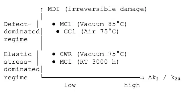
Figure D2. Combined mechanical drift representation
The figure illustrates that MDI predominantly tracks irreversible deformation localization (Δk₂), whereas pronounced changes in Δk₁ and ΔAy may occur at relatively low MDI values, indicating degradation regimes dominated by elastic stress accumulation rather than permanent structural damage.
Appendix D.2. Illustrative effect of environment on mechanical response (CC1 anode)
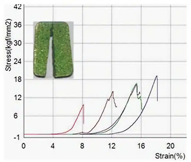
Figures D3 and D4 provide an illustrative comparison of the mechanical response of the same anode design (CC1) after reverse-bias exposure under vacuum and high-humidity air. The comparison highlights qualitative differences in plastic accommodation and deformation localization associated with environmental conditions. These data are included for visualization purposes only and are not used for quantitative analysis or MDI evaluation. The observed contrast is consistent with the interpretation of atmosphere-assisted stabilization of stressed interfacial states discussed in Sections 3.4–3.6.
References
1 A. Teverovsky Kinetics of Moisture Sorption and Reverse Bias Degradation in Chip Tantalum Capacitors https://passive-components.eu › uploads › 2017/10
2 A. Teverovsky Kinetics of Moisture Sorption and Reverse Bias Degradation in Chip Tantalum Capacitors NASA Electronic Parts and Packaging (NEPP) Program Presented by Alexander Teverovsky at Passive Components Networking Days, Brno, Czech Republic, September 12-15, 2017
3 V. Azbel Tantalum Capacitor Reliability Estimation Based on Anode Screening https://passive-components.eu/tantalum-capacitor-reliability-estimation-based-on-anode-screening/
4. V. Azbel: Structural Interpretation of Reliability in Tantalum Capacitor Anodes