Passive Components Blog
No Result
View All Result
  • Home
  • NewsFilter
    • All
    • Aerospace & Defence
    • Antenna
    • Applications
    • Automotive
    • Capacitors
    • Circuit Protection Devices
    • electro-mechanical news
    • Filters
    • Fuses
    • Inductors
    • Industrial
    • Integrated Passives
    • inter-connect news
    • Market & Supply Chain
    • Market Insights
    • Medical
    • Modelling and Simulation
    • New Materials & Supply
    • New Technologies
    • Non-linear Passives
    • Oscillators
    • Passive Sensors News
    • Resistors
    • RF & Microwave
    • Telecommunication
    • Weekly Digest

    Würth Elektronik Releases Long Life SMT nano and microSD Card Connectors

    Glass Core Technology Breakthrough Potential for High-Speed Interconnects

    YAGEO Releases High Isolation Transformer for 1500VDC Applications

    Bourns Releases 1500VDC Power Fuse for Photovoltaic Applications

    Murata Releases Worlds First Molded Thermistor with Wire-Bonding

    Vishay Extends Axial Wirewound Resistors with WSZ Lead Form

    Smoltek CNF-MIM Capacitor Commercialization Update

    Bourns Unveils Automotive Thick Film on Steel

    TT Electronics Releases Failsafe and High Surge SMD MELF Resistors

    Trending Tags

    • Ripple Current
    • RF
    • Leakage Current
    • Tantalum vs Ceramic
    • Snubber
    • Low ESR
    • Feedthrough
    • Derating
    • Dielectric Constant
    • New Products
    • Market Reports
  • VideoFilter
    • All
    • Antenna videos
    • Capacitor videos
    • Circuit Protection Video
    • Filter videos
    • Fuse videos
    • Inductor videos
    • Inter-Connect Video
    • Non-linear passives videos
    • Oscillator videos
    • Passive sensors videos
    • Resistor videos

    Understanding Switched Capacitor Converters

    Coupled Inductors Circuit Model and Examples of its Applications

    Inductor Resonances and its Impact to EMI

    Highly Reliable Flex Rigid PCBs, Würth Elektronik Webinar

    Causes of Oscillations in Flyback Converters

    How to design a 60W Flyback Transformer

    Modeling and Simulation of Leakage Inductance

    Power Inductor Considerations for AI High Power Computing – Vishay Video

    Coupled Inductors in Multiphase Boost Converters

    Trending Tags

    • Capacitors explained
    • Inductors explained
    • Resistors explained
    • Filters explained
    • Application Video Guidelines
    • EMC
    • New Products
    • Ripple Current
    • Simulation
    • Tantalum vs Ceramic
  • Knowledge Blog
  • Suppliers
    • Who is Who
  • Events
No Result
View All Result
Passive Components Blog
No Result
View All Result

Method for determining the reliability of a tantalum capacitor

9.1.2020
Reading Time: 6 mins read
A A

Vladimir Azbel published an article on his LinkedIn profile on reliability assessment of a tantalum capacitor.

The task set is to show the ability to predict the behavior of the electrical characteristics of the capacitance (C- CV / g ) and leakage current (DCL ) of the capacitor at the sinter pellet stage.

RelatedPosts

Würth Elektronik Releases Long Life SMT nano and microSD Card Connectors

Glass Core Technology Breakthrough Potential for High-Speed Interconnects

YAGEO Releases High Isolation Transformer for 1500VDC Applications

It is assumed that the capacitance of the capacitor depends on the porosity, and the leakage current behavior (DCL) depends on the neck properties of the frame material.

How the problem is solved:

The existing sinter pellet control method, by shrinkage, does not provide information about the neck and does not unambiguously reflect the change in porosity.

The proposed method, based on the mechanical characteristics of the sinter pellet, allows you to control changes in the porosity, size and defects of the neck depending on the powder and the manufacturing process.

Tantalum capacitors are widely used in the manufacture of electronic equipment for special applications, such as military, aerospace and medical, due to their high stability and reliability.

The tantalum capacitor is characterized by four electrical parameters. Of these four parameters, the capacitance and leakage currents are directly dependent on the design of the sinter pellet. For example: capacitor capacitance depends directly on the specific surface of the sinter pellet

Sinter pellet is a PM product representing pressed and sintered tantalum powder.

The manufacture of a tantalum capacitor is a lot – a step-by-step process and determining the possible causes of DCL failures associated with the production of a sinter pellet having a porous structure is not possible using existing methods of control for shrinkage or porosity. For this, an approach based on modeling a porous structure is used to predict its effect on the finished capacitor.

Production a predetermined capacitor design is primarily associated with obtaining the necessary sinter pellet porous structure, which is achieved by optimizing, on the one hand, the powder parameters: the size of its primary particle, their distribution curve, temperature agglomeration, and sintering activity; on the other hand, with technological parameters: pressing density (dg), temperature (Ts) and sintering time (t).

A structure has already been formed in the sinter pellet which defines the main characteristics of the capacitor, such as capacitance (C) and behavior, leakage current (DCL).

An increase in sinter density pellet, due to an increase in dg, leads to a decrease in C and DCL

If the capacitance of the capacitor, clearly, will be controlled by the sinter pellet porosity, and the leakage current (DCL) is associated with the defect of the dielectric. It is logical to assume that DCLs depend on the properties of the base material, i.e. from the metal frame, of a porous material, the most defective place located of which is the neck, which is the reason for the problems that occurred during electrolysis.

The sinter pellet control, when varying dg and Ts, by the standard method, allows to determine shrinkage and its changes, through its linear dimensions, but does not provide information about porosity, neck size and defect and their changes ..

The change in porosity and defects in PM products, depending on dg and Ts, is controlled by mechanical methods, in particular, by stress-strain curve.

The goal of this work is to show the relationship between the mechanical characteristics (σym, E, n) of the sinter pellets received from the stress-strain curve: with shrinkage and capacitor parameters: CV / g and DCL behavior, depending on the pressing density (dg), sintering temperature (Ts) and type of powder. This will allow the mechanical characteristics of sinter pellets to be used to predict, behavior CV /g and DCL of capacitor.

Using the proposed method will allow at the sinter pellet stage, based on a comparison of the mechanical characteristics of the tested sinter pellet, with similar characteristics of the sinter pellet selected as a benchmark:

  • control sintering process acceptability
  • control of acceptability of a new batch of powder
  • control acceptable of the powder of the same type as an alternative supplier
  • choice of the optimal sinter pellet design, when building the matrix

Comparison of the tested sinter pellet with its control analog (benchmark ), which is determined by the person responsible for its quality, increases the reliability of forecasting.

The reliability of predicting the behavior of the CV / g and DCL capacitor by the proposed method increases significantly if the mechanical characteristics of the tested sinter pellet used for the production of the capacitor are compared with similar characteristics of the sinter pellet, the design of which made it possible to receive a reliable capacitor.

Thus, at the sinter pellet stage, one can predict the behavior of the electrical characteristics of the CV/g and DCL capacitor

Mechanical inline test predicts tantalum capacitor reliability and reduces the production cost

Tantalum capacitors are widely used because of their unique high capacitance, high breakdown voltage, and relatively small sizes. Due to high-reliability tantalum capacitors are also used in military, aerospace and medical devices.

Tantalum capacitor production comprises fine Ta powder shaping and sintering into the pellets (anodes), the electrochemical formation of the Ta-oxide dielectric layer. Some inline measurements allow managing output parameters of the capacitor, but the reliability test is capable only at the end of the process. Based on the long-time investigations we found out that the reliability of the tantalum capacitor depends on the mechanical properties of the sintered pellet. Therefore the results of our special mechanical test of the sintered pellet can definitely predict the reliability behavior of the packaged capacitor. The prediction of the reliability properties of the tantalum capacitors at the early steps of the technological process saves the production cost. Below is the chart showing a correlation between the mechanical properties of the tantalum sintered pellet and the reliability behavior of the tantalum capacitor:

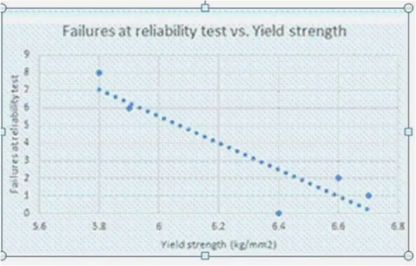
Mechanical stress of anodized pellet predicts the Ta-capacitor reliability

We have already discussed (see above) how the yield strength of a sintered Ta pellet (Ϭs) made from powders of the one grade, but from different vendors, allows predicting the reliability of a Ta-capacitor made from one recipe.

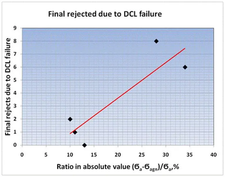
The value Ϭs may be sufficient when choosing an acceptable powder for the existing anodization recipe, but not representative enough for reliability indicators of Ta-capacitors, when it is necessary to choose an anodization recipe acceptable for specific sintered pellet. Anodization cause the formation of an amorphous film Ta2O5, which lead to created of defects in the anode (sintered pellet after anodization) and can affect the yield strength anode (Ϭa).

We offer an additional test to predict the reliability of tantalum capacitors by the ratio of the difference in the yield strength anode before (Ϭa) and after aging at 450°C (Ϭagn) to the Ϭa. In the case of an increase in this indicator, an increase in the number of failures is expected during the reliability test. Therefore, if the ratio trends to zero, it is assumed that reliability failures will be low. The graph below shows a very clear correlation between this ratio expressed as a percentage and the number of failures:

Related

Source: Vladimir Azbel Linked In Blog

Recent Posts

Smoltek CNF-MIM Capacitor Commercialization Update

11.6.2025
13

Understanding Switched Capacitor Converters

9.6.2025
50

Exxelia to Present Smart Integrated Magnetics and MML Film Capacitors at SIAE25 

6.6.2025
28

Knowles Extends Range and Performance of C0G MLCC Capacitors

6.6.2025
22

Panasonic Releases New Aluminum Hybrid Capacitors with High Ripple Current in Compact Size

6.6.2025
22

5th PCNS Conference Registration Now Open!

5.6.2025
23

YAGEO Introduces Automotive Supercapacitors for Stable BMS in EVs

5.6.2025
27

Capacitance Definition of Non-Linear Voltage Dependent Capacitors

5.6.2025
30

Passive Electronic Components Lead-times Update

4.6.2025
67

Quantic Eulex Presents Ceramic Gap RF Capacitors

12.6.2025
28

Upcoming Events

Jun 24
17:00 - 18:00 CEST

Ultra-Compact and Efficient Switched-Capacitor Power Converters

Jul 23
13:00 - 14:00 CEST

PCB design for a Smartwatch

View Calendar

Popular Posts

  • Buck Converter Design and Calculation

    0 shares
    Share 0 Tweet 0
  • Boost Converter Design and Calculation

    0 shares
    Share 0 Tweet 0
  • Flyback Converter Design and Calculation

    0 shares
    Share 0 Tweet 0
  • What is a Dielectric Constant and DF of Plastic Materials?

    4 shares
    Share 4 Tweet 0
  • LLC Resonant Converter Design and Calculation

    0 shares
    Share 0 Tweet 0
  • Ripple Current and its Effects on the Performance of Capacitors

    3 shares
    Share 3 Tweet 0
  • SEPIC Converter Design and Calculation

    0 shares
    Share 0 Tweet 0
  • Dual Active Bridge (DAB) Topology Explained

    0 shares
    Share 0 Tweet 0
  • How to Design an Inductor

    0 shares
    Share 0 Tweet 0
  • Flying Capacitors Explained

    0 shares
    Share 0 Tweet 0

Newsletter Subscription


Passive Components Blog

© EPCI - Leading Passive Components Educational and Information Site

  • Home
  • Privacy Policy
  • EPCI Membership & Advertisement
  • About

No Result
View All Result
  • Home
  • Knowledge Blog
  • Premium Suppliers

© EPCI - Leading Passive Components Educational and Information Site

This website uses cookies. By continuing to use this website you are giving consent to cookies being used. Visit our Privacy and Cookie Policy.
Go to mobile version