Passive Components Blog
No Result
View All Result
  • Home
  • NewsFilter
    • All
    • Aerospace & Defence
    • Antenna
    • Applications
    • Automotive
    • Capacitors
    • Circuit Protection Devices
    • electro-mechanical news
    • Filters
    • Fuses
    • Inductors
    • Industrial
    • Integrated Passives
    • inter-connect news
    • Market & Supply Chain
    • Market Insights
    • Medical
    • Modelling and Simulation
    • New Materials & Supply
    • New Technologies
    • Non-linear Passives
    • Oscillators
    • Passive Sensors News
    • Resistors
    • RF & Microwave
    • Telecommunication
    • Weekly Digest

    Nanocrystalline Cores for Low‑Loss MHz Chip Inductors

    Exxelia Miniaturized 400 MHz Inverted‑F Antenna

    Würth Elektronik Unveils High-Current Automotive Power Inductor

    Transformer-Based Power-Line Harvester Magnetic Design

    Tantalum Capacitor Anode Manufacturing Quality Management

    Middle East Conflict: The Potential Impact to Passive Components

    Wk 12 Electronics Supply Chain Digest

    Designing a 2 kW LLC Transformer with Integrated Resonant Inductor

    Inductor Technology Dossier

    Trending Tags

    • Ripple Current
    • RF
    • Leakage Current
    • Tantalum vs Ceramic
    • Snubber
    • Low ESR
    • Feedthrough
    • Derating
    • Dielectric Constant
    • New Products
    • Market Reports
  • VideoFilter
    • All
    • Antenna videos
    • Capacitor videos
    • Circuit Protection Video
    • Filter videos
    • Fuse videos
    • Inductor videos
    • Inter-Connect Video
    • Non-linear passives videos
    • Oscillator videos
    • Passive sensors videos
    • Resistor videos

    Transformer-Based Power-Line Harvester Magnetic Design

    Thermal Modeling of Magnetics

    Standard vs Planar LLC transformers Comparison for Battery Chargers

    How Modern Tools Model Magnetic Components for Power Electronics

    Advanced Loss Modeling for Planar Magnetics in the Frenetic Planar Tool

    2026 Power Magnetics Design Trends: Flyback, DAB and Planar

    Enabling Software‑Defined Vehicle Architectures: Automotive Ethernet and Zonal Smart Power

    Calculating Resistance Value of a Flyback RC Snubber 

    One‑Pulse Characterization of Nonlinear Power Inductors

    Trending Tags

    • Capacitors explained
    • Inductors explained
    • Resistors explained
    • Filters explained
    • Application Video Guidelines
    • EMC
    • New Products
    • Ripple Current
    • Simulation
    • Tantalum vs Ceramic
  • Knowledge Blog
  • DossiersNew
  • Suppliers
    • Who is Who
  • PCNS
    • PCNS 2025
    • PCNS 2023
    • PCNS 2021
    • PCNS 2019
    • PCNS 2017
  • Events
No Result
View All Result
Passive Components Blog
No Result
View All Result

Modelithics Microwave Supermodels Expands to mmWave Range

29.2.2024
Reading Time: 5 mins read
A A

Modelithics‘ ongoing initiative Modelithics Microwave Supermodels offers increasingly more models validated to higher frequencies (like mmWave range 50 or 67 GHz) for components in which higher-frequency validation makes sense.

There’s no question that mmWave frequencies have received a great deal of attention in recent years. Of course, much of this interest revolves around 5G along with the emerging topic of 6G. As a mmWave application space, 5G has been under the microscope for some time now.

RelatedPosts

Modelithics Library for MATLAB: Measurement-Based Models for Microwave and RF Passive Components

Modelithics Releases Component Model Library for SIMULIA CST Studio Suite

Modelithics COMPLETE Library v25.8 for Keysight ADS

Of course, the need for mmWave frequencies also extends to other arenas—for instance, mmWave radar is another application that demands performance at these higher frequencies.

Having said all this, one thing is clear: many companies recognize the need to offer products that perform at frequencies higher than ever before. For Modelithics, one ongoing initiative is to offer increasingly more models validated to higher frequencies (like 50 or 67 GHz) for components in which higher-frequency validation makes sense. This initiative not only applies to new models being released but also models originally developed in years past.

Many of these higher-frequency models were introduced in the latest version of the Modelithics COMPLETE Library. These models are also included in the Modelithics mmWave and 5G Library (every model in the mmWave and 5G Library is validated to at least 30 GHz—some as high as 125 GHz). We mentioned how this higher-frequency initiative is relevant even to existing models. Let’s explain that by talking about Modelithics Microwave Supermodels, which were introduced several years back.

One of the first Microwave Supermodels is the model for the Coilcraft 0402CS inductor series. When this model was first introduced as model number IND-CLC-0402-001, it was validated to 10 GHz and covered part values ranging from 1 to 47nH. It also had a substrate-scalability range (i.e., substrate height divided by dielectric constant) of 1 to 8 mils.

Figure 1. Model features of the IND-CLC-0402-201 model.

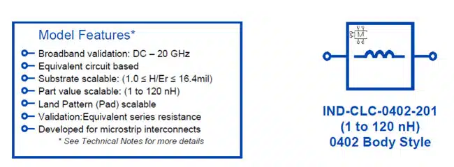
A second version was later introduced, followed by the currently available Microwave Supermodel (model number IND-CLC-0402-201). This Microwave Supermodel is validated to 20 GHz, covers a part-value range of 1 to 120 nH, and has a substrate scalability range of 1 to 16.4 mils (Fig. 1). It’s clear these numbers represent a pretty big jump compared to the original model.

Now, you’ll notice the IND-CLC-0402-201 Microwave Supermodel is validated to 20 GHz, which may seem like a pretty high frequency. But as mentioned earlier, Modelithics is currently making a push to extend the validated frequency range of certain models well beyond the original frequency range. That’s why you can now find Microwave Supermodels validated to frequencies much higher in comparison to the original models.

You may be wondering how all this is possible. Remember that the models being discussed here are based on actual lab measurements performed at Modelithics. So, these models really begin with the Modelithics lab team, which has extensive experience performing precise measurements of components mounted on printed-circuit-boards (PCBs) at frequencies to 110 GHz and even beyond.

A Microwave Supermodel is spawned when an existing Modelithics model is enhanced to allow for a wider range of performance. These performance enhancements include validations on additional substrates to enable a wider substrate scalability range. Other model enhancements include extending the validated frequency range and extending the part-value range.

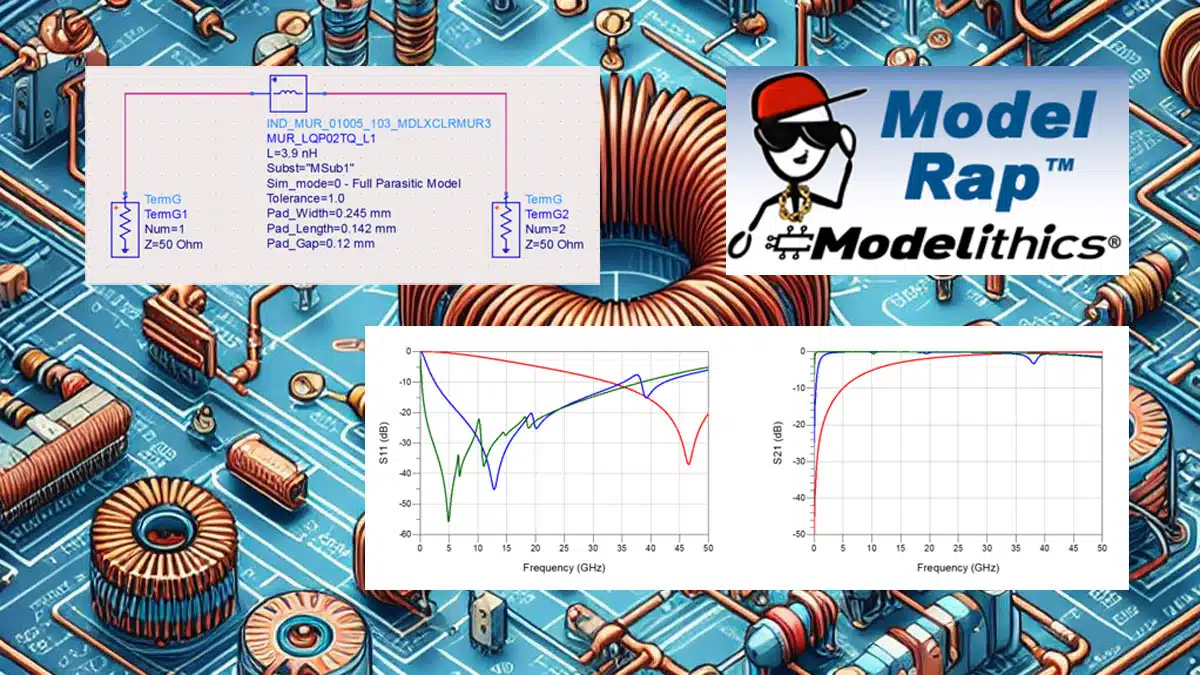
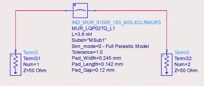
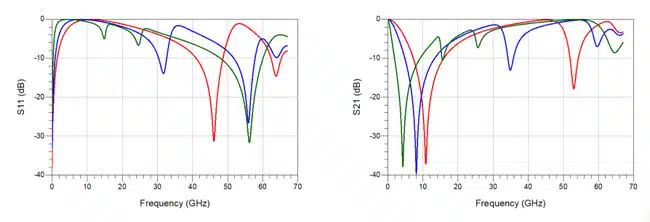
Let’s now take a closer look at these higher-frequency Microwave Supermodels. We’ll stick with inductors by examining the model for the Murata LQP02TQ series. When this model was first introduced as model number IND-MUR-01005-003, it had a validated frequency range of DC to 30 GHz. That model was recently replaced with an updated version (model number IND-MUR-01005-103) that’s validated to 67 GHz. Figure 2 shows a schematic that includes this model in a two-port series configuration. The substrate used for this simulation is 4-mil-thick Rogers RO4350B. Figure 3 shows the simulated S11 and S21 for three inductance values. Note that the IND-MUR-01005-103 model covers an inductance range of 0.4 to 22 nH.

Figure 2. Simple schematic that includes the IND-MUR-01005-103 model in a two-port series configuration.
Figure 3. Simulated S11 (left) and S21 (right) of the IND-MUR-01005-103 model in a two-port series configuration. Red: 3.9 nH; Blue: 6.8 nH; Green: 22 nH.

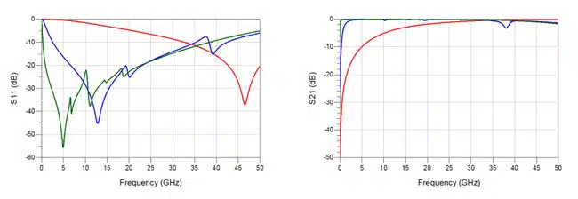
Let’s move beyond inductors and turn our attention to capacitors. In this case, let’s focus on the model for the Kemet CBR02 series (model number CAP-KMT-0201-201). This model is validated to 50 GHz, while the original model (model number CAP-KMT-0201-001) was only validated to 20 GHz. Figure 4 shows the simulated (two-port series configuration) S11 and S21 for three capacitance values. The substrate used this time is 6.6-mil-thick Rogers RO4350B. Note that the CAP-KMT-0201-201 model covers a capacitance range of 0.1 to 39 pF.

Figure 4. Simulated S11 (left) and S21 (right) of the CAP-KMT-0201-201 model in a two-port series configuration. Red: 0.1 pF; Blue: 1.8 pF; Green: 18 pF.

On a final note, expect to see more of these higher-frequency Microwave Supermodels in the future. On top of that, be on the lookout for application notes and other content in the days ahead that demonstrate practical higher-frequency design examples made possible by Microwave Supermodels as well as brand new models validated to higher frequencies.

References

  1. I. Bedford, H. Patel, and L. Levesque, “Application Note 058: Accelerating Designs With Modelithics Microwave
    Supermodels™.”
  2. C. DeMartino, E. O’Dell, and L. Dunleavy, “Application Note 067: Utilizing Substrate Scalability of Modelithics Models in
    Keysight ADS.”
  3. Modelithics literature: https://www.modelithics.com/Literature/AppNote

Related

Source: Modelithics

Recent Posts

Nanocrystalline Cores for Low‑Loss MHz Chip Inductors

25.3.2026
5

Exxelia Miniaturized 400 MHz Inverted‑F Antenna

24.3.2026
7

Würth Elektronik Unveils High-Current Automotive Power Inductor

24.3.2026
13

Transformer-Based Power-Line Harvester Magnetic Design

24.3.2026
6

Tantalum Capacitor Anode Manufacturing Quality Management

23.3.2026
16

Middle East Conflict: The Potential Impact to Passive Components

23.3.2026
73

Designing a 2 kW LLC Transformer with Integrated Resonant Inductor

20.3.2026
48

Inductor Technology Dossier

19.3.2026
46

Coilcraft Releases TLVR Inductors for High Density VRMs and PoL Converters

19.3.2026
40

Upcoming Events

Apr 21
16:00 - 17:00 CEST

Heatsink Solutions: Thermal Management in electronic devices

May 5
16:00 - 17:00 CEST

Understanding and Selecting Capacitors – Fundamentals, Technologies and Latest Trends

May 19
16:00 - 17:00 CEST

Designing Qi2 Wireless Power Systems: Practical Development and EMC Optimization

View Calendar

Popular Posts

  • Buck Converter Design and Calculation

    0 shares
    Share 0 Tweet 0
  • Boost Converter Design and Calculation

    0 shares
    Share 0 Tweet 0
  • Flyback Converter Design and Calculation

    0 shares
    Share 0 Tweet 0
  • LLC Resonant Converter Design and Calculation

    0 shares
    Share 0 Tweet 0
  • MLCC and Ceramic Capacitors

    0 shares
    Share 0 Tweet 0
  • Dual Active Bridge (DAB) Topology

    0 shares
    Share 0 Tweet 0
  • MLCC Manufacturers Consider Price Increase as AI Demand Outpaces Supply

    0 shares
    Share 0 Tweet 0
  • Ripple Current and its Effects on the Performance of Capacitors

    3 shares
    Share 3 Tweet 0
  • MLCC Case Sizes Standards Explained

    0 shares
    Share 0 Tweet 0
  • What is a Dielectric Constant and DF of Plastic Materials?

    4 shares
    Share 4 Tweet 0

Newsletter Subscription


Passive Components Blog

© EPCI - Leading Passive Components Educational and Information Site

  • Home
  • Privacy Policy
  • EPCI Membership & Advertisement
  • About

No Result
View All Result
  • Home
  • Knowledge Blog
  • PCNS

© EPCI - Leading Passive Components Educational and Information Site

This website uses cookies. By continuing to use this website you are giving consent to cookies being used. Visit our Privacy and Cookie Policy.
Go to mobile version