Passive Components Blog
No Result
View All Result
  • Home
  • NewsFilter
    • All
    • Aerospace & Defence
    • Antenna
    • Applications
    • Automotive
    • Capacitors
    • Circuit Protection Devices
    • electro-mechanical news
    • Filters
    • Fuses
    • Inductors
    • Industrial
    • Integrated Passives
    • inter-connect news
    • Market & Supply Chain
    • Market Insights
    • Medical
    • Modelling and Simulation
    • New Materials & Supply
    • New Technologies
    • Non-linear Passives
    • Oscillators
    • Passive Sensors News
    • Resistors
    • RF & Microwave
    • Telecommunication
    • Weekly Digest

    Researchers Demonstrated High Energy Ceramic Capacitors Stable in Wide Temperature Range

    Stackpole Offers High Voltage Plate Resistors up to 40KV

    How to Manage Supercapacitors Leakage Current and Self Discharge 

    Qualification of Commercial Supercapacitors for Space Applications

    Experimental Evaluation of Wear Failures in SMD Inductors

    Resonant Capacitors in High-Power Resonant Circuits

    a Schematic diagram of the BNT-based components constructed based on the entropy-increase strategy. b Digital photograph, cross-sectional SEM image, and EDS mappings of the MLCCs. c Unipolar P-E loops of MLCCs as a function of applied E. d Wrec and η of the MLCCs as a function of applied E. The comparison of (e) Wrec and η, (f) η and UF of the MLCCs with those of other recently reported state-of-the-art MLCCs. source: Nature Communications

    Researchers Proposed Enhanced Energy Storage MLCC

    Littelfuse Releases First Reflow-Compatible Illuminated Tactile Switch

    Vishay Unveils 5W Power Metal Strip Resistor in Compact 1206 Case Size

    Trending Tags

    • Ripple Current
    • RF
    • Leakage Current
    • Tantalum vs Ceramic
    • Snubber
    • Low ESR
    • Feedthrough
    • Derating
    • Dielectric Constant
    • New Products
    • Market Reports
  • VideoFilter
    • All
    • Antenna videos
    • Capacitor videos
    • Circuit Protection Video
    • Filter videos
    • Fuse videos
    • Inductor videos
    • Inter-Connect Video
    • Non-linear passives videos
    • Oscillator videos
    • Passive sensors videos
    • Resistor videos

    Efficient Power Converters: Duty Cycle vs Conduction Losses

    Ripple Steering in Coupled Inductors: SEPIC Case

    SEPIC Converter with Coupled and Uncoupled Inductors

    Coupled Inductors in SEPIC versus Flyback Converters

    Non-Linear MLCC Class II Capacitor Measurements Challenges

    Percolation Phenomenon and Reliability of Molded Power Inductors in DC/DC converters

    Root Causes and Effects of DC Bias and AC in Ceramic Capacitors

    How to Calculate the Output Capacitor for a Switching Power Supply

    Switched Capacitor Converter Explained

    Trending Tags

    • Capacitors explained
    • Inductors explained
    • Resistors explained
    • Filters explained
    • Application Video Guidelines
    • EMC
    • New Products
    • Ripple Current
    • Simulation
    • Tantalum vs Ceramic
  • Knowledge Blog
  • Suppliers
    • Who is Who
  • Events
No Result
View All Result
Passive Components Blog
No Result
View All Result

Murata introducing 0805 inch 6A highest impedance ferrite beads for automotive power supplies

19.3.2018
Reading Time: 2 mins read
A A

Source: Murata news

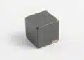
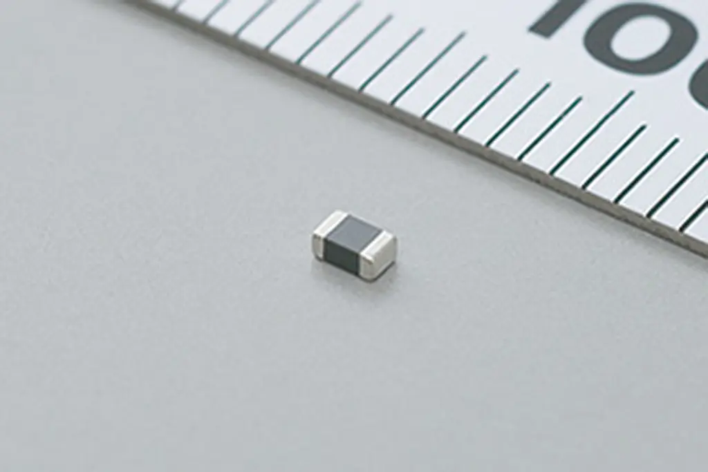
Murata Manufacturing Co., Ltd. has introduced the 0805 inch (2.0mm x 1.25mm) BLM21SP series of chip ferrite beads for use in automotive power train safety applications.
This product has a rated current of 6A and also an impedance of 70Ω, the highest in the industry. In addition, it is expected to provide a high degree of noise immunity. By using the BLM21SP series on power lines which are liable to generate noise, they can assist in enabling these power lines to meet various noise standards such as CISPR25. Mass production of this product commenced in March 2018.

RelatedPosts

Researchers Demonstrated High Energy Ceramic Capacitors Stable in Wide Temperature Range

Stackpole Offers High Voltage Plate Resistors up to 40KV

How to Manage Supercapacitors Leakage Current and Self Discharge 

Background
In the automotive industry in recent years, large-scale electronic devices are being mounted on vehicles such as hybrid automobiles and electric vehicles, along with the automation of various functions. As a result, conductive noise and radiation noise is increasing, and there are greater demands for noise reduction measures.

Particularly, in the case of power lines which carry large currents, noise issues are liable to occur, and countermeasures are necessary. However, it is difficult to design high-impedance noise reduction components which can be used at the high rated currents carried by power lines.

Murata has enhanced the impedance acquisition efficiency due to the adoption of new internal electrode forming technology and optimization of structural design. As a result of this technology, whereas the BLM21PG series, which is Murata’s existing power product intended for power supply use, has a rated current of 6A and an impedance of 22Ω at 100MHz, the new product has a rated current of 6A and realizes a high impedance of 70Ω at 100MHz, which is more than twice that of the previous product. Also, a comparison of the new and old products for the same impedance value reveals that the rated current of the new product is at least 1.5 times that of the old product.

From now on, Murata intends to develop a lineup that has even higher impedance values, and will also expand its range of high-temperature products.

Features

  • Supports power train safety in automobiles.
  • Conforms to AEC-Q200.
  • Is compact (2.0 x 1.25mm) and has a high maximum rated current of 6A.
  • A large current, high impedance lineup (70Ω/6A, 110Ω/5A, 180Ω/4A) is available.

Electric characteristics
Performance comparison between BLM21SP series and BLM21PG series

Related

Recent Posts

Researchers Demonstrated High Energy Ceramic Capacitors Stable in Wide Temperature Range

2.10.2025
1

How to Manage Supercapacitors Leakage Current and Self Discharge 

1.10.2025
12

Experimental Evaluation of Wear Failures in SMD Inductors

1.10.2025
14

Resonant Capacitors in High-Power Resonant Circuits

1.10.2025
8

Vishay Unveils 5W Power Metal Strip Resistor in Compact 1206 Case Size

1.10.2025
10

Polymer Tantalum Capacitors Beyond AEC-Q200 LEO Satellites

30.9.2025
31

Flaked Tantalum Powders: High Capacitance Powders for High Reliable Tantalum Capacitors

29.9.2025
14

Efficient Power Converters: Duty Cycle vs Conduction Losses

29.9.2025
15

Design of High Precision Integrated Resistive Voltage Dividers

29.9.2025
28

Samsung Electro-Mechanics Releases 470nF 16V MLCC in 0402 Size

29.9.2025
15

Upcoming Events

Oct 8
11:00 - 12:00 CEST

PCB Online Shop – simply “Made in Germany” by Würth Elektronik

Oct 14
16:00 - 17:00 CEST

Smart Sensors, Smarter AI: Building Reliable Edge Systems

Oct 17
12:00 - 14:00 EDT

External Visual Inspection per MIL-STD-883 TM 2009

Oct 20
October 20 - October 23

Digital WE Days 2025 – Virtual Conference

Oct 21
October 21 @ 12:00 - October 23 @ 14:15 EDT

Space and Military Standards for Hybrids and RF Microwave Modules

View Calendar

Popular Posts

  • Buck Converter Design and Calculation

    0 shares
    Share 0 Tweet 0
  • Boost Converter Design and Calculation

    0 shares
    Share 0 Tweet 0
  • Flyback Converter Design and Calculation

    0 shares
    Share 0 Tweet 0
  • LLC Resonant Converter Design and Calculation

    0 shares
    Share 0 Tweet 0
  • Dual Active Bridge (DAB) Topology Explained

    0 shares
    Share 0 Tweet 0
  • SEPIC Converter Design and Calculation

    0 shares
    Share 0 Tweet 0
  • What is a Dielectric Constant and DF of Plastic Materials?

    4 shares
    Share 4 Tweet 0
  • Ripple Current and its Effects on the Performance of Capacitors

    3 shares
    Share 3 Tweet 0
  • MLCC and Ceramic Capacitors

    0 shares
    Share 0 Tweet 0
  • Flying Capacitors Explained

    0 shares
    Share 0 Tweet 0

Newsletter Subscription


Passive Components Blog

© EPCI - Leading Passive Components Educational and Information Site

  • Home
  • Privacy Policy
  • EPCI Membership & Advertisement
  • About

No Result
View All Result
  • Home
  • Knowledge Blog
  • Premium Suppliers

© EPCI - Leading Passive Components Educational and Information Site

This website uses cookies. By continuing to use this website you are giving consent to cookies being used. Visit our Privacy and Cookie Policy.
Go to mobile version