Passive Components Blog
No Result
View All Result
  • Home
  • NewsFilter
    • All
    • Aerospace & Defence
    • Antenna
    • Applications
    • Automotive
    • Capacitors
    • Circuit Protection Devices
    • electro-mechanical news
    • Filters
    • Fuses
    • Inductors
    • Industrial
    • Integrated Passives
    • inter-connect news
    • Market & Supply Chain
    • Market Insights
    • Medical
    • Modelling and Simulation
    • New Materials & Supply
    • New Technologies
    • Non-linear Passives
    • Oscillators
    • Passive Sensors News
    • Resistors
    • RF & Microwave
    • Telecommunication
    • Weekly Digest

    Littelfuse Announced TVS Diodes for 48 V Automotive Systems

    Spectrum Controls Joins Modelithics Program to Offer High‑Fidelity RF Models for Resistors, Attenuators and Terminations

    RF Filters and Passive Components Enabling the 7 Missile RF Subsystems

    Ferrite versus Nanocrystalline Power Inductor Cores: Turns, Gap and Size

    YAGEO Presents NANOMET Soft Magnetic Cores for High‑Density Power Conversion

    Coilcraft Releases High-Current Ferrite Beads for CISPR 25 EMC compliance

    From DCL to SSC: Bridging Electrical Symptoms and Structural Indicators in Tantalum Capacitors

    Vishay Unveils Multi-Turn Position Sensor for Harsh Industrial Environments

    YAGEO Introduces Automotive MOV Surge Protection Varistor

    Trending Tags

    • Ripple Current
    • RF
    • Leakage Current
    • Tantalum vs Ceramic
    • Snubber
    • Low ESR
    • Feedthrough
    • Derating
    • Dielectric Constant
    • New Products
    • Market Reports
  • VideoFilter
    • All
    • Antenna videos
    • Capacitor videos
    • Circuit Protection Video
    • Filter videos
    • Fuse videos
    • Inductor videos
    • Inter-Connect Video
    • Non-linear passives videos
    • Oscillator videos
    • Passive sensors videos
    • Resistor videos

    Ferrite versus Nanocrystalline Power Inductor Cores: Turns, Gap and Size

    KYOCERA AVX Presents Antenna Integrator Studio Tutorial for Antenna Placement and RF Design

    Power Design Simulation Tools for Faster Inductor Selection and Loss Optimization

    EMC‑Compliant PCB and Connector Design Guidelines

    Why Isolated DC/DC Power Supplies Fail Late, Würth Elektronik Podcast

    Designing 800 V DC EMC Filters: Calculation, Simulation and Measurement

    Current Sense Transformer Datasheet and Design‑in Guide

    Designing a USB Type‑C Flyback Planar Transformer with Frenetic’s Planar Tool

    Magnetics Design in High‑Frequency GaN Converters

    Trending Tags

    • Capacitors explained
    • Inductors explained
    • Resistors explained
    • Filters explained
    • Application Video Guidelines
    • EMC
    • New Products
    • Ripple Current
    • Simulation
    • Tantalum vs Ceramic
  • Knowledge Blog
  • Dossiers
    • AI Hardware Dossier
    • Power Converter Dossier
    • Automotive Dossier
    • Capacitor Dossier
    • Resistor Dossier
    • Inductor Dossier
    • Circuit Protection Dossier
  • Suppliers
    • Who is Who
  • PCNS
    • PCNS 2025
    • PCNS 2023
    • PCNS 2021
    • PCNS 2019
    • PCNS 2017
  • Events
  • Home
  • NewsFilter
    • All
    • Aerospace & Defence
    • Antenna
    • Applications
    • Automotive
    • Capacitors
    • Circuit Protection Devices
    • electro-mechanical news
    • Filters
    • Fuses
    • Inductors
    • Industrial
    • Integrated Passives
    • inter-connect news
    • Market & Supply Chain
    • Market Insights
    • Medical
    • Modelling and Simulation
    • New Materials & Supply
    • New Technologies
    • Non-linear Passives
    • Oscillators
    • Passive Sensors News
    • Resistors
    • RF & Microwave
    • Telecommunication
    • Weekly Digest

    Littelfuse Announced TVS Diodes for 48 V Automotive Systems

    Spectrum Controls Joins Modelithics Program to Offer High‑Fidelity RF Models for Resistors, Attenuators and Terminations

    RF Filters and Passive Components Enabling the 7 Missile RF Subsystems

    Ferrite versus Nanocrystalline Power Inductor Cores: Turns, Gap and Size

    YAGEO Presents NANOMET Soft Magnetic Cores for High‑Density Power Conversion

    Coilcraft Releases High-Current Ferrite Beads for CISPR 25 EMC compliance

    From DCL to SSC: Bridging Electrical Symptoms and Structural Indicators in Tantalum Capacitors

    Vishay Unveils Multi-Turn Position Sensor for Harsh Industrial Environments

    YAGEO Introduces Automotive MOV Surge Protection Varistor

    Trending Tags

    • Ripple Current
    • RF
    • Leakage Current
    • Tantalum vs Ceramic
    • Snubber
    • Low ESR
    • Feedthrough
    • Derating
    • Dielectric Constant
    • New Products
    • Market Reports
  • VideoFilter
    • All
    • Antenna videos
    • Capacitor videos
    • Circuit Protection Video
    • Filter videos
    • Fuse videos
    • Inductor videos
    • Inter-Connect Video
    • Non-linear passives videos
    • Oscillator videos
    • Passive sensors videos
    • Resistor videos

    Ferrite versus Nanocrystalline Power Inductor Cores: Turns, Gap and Size

    KYOCERA AVX Presents Antenna Integrator Studio Tutorial for Antenna Placement and RF Design

    Power Design Simulation Tools for Faster Inductor Selection and Loss Optimization

    EMC‑Compliant PCB and Connector Design Guidelines

    Why Isolated DC/DC Power Supplies Fail Late, Würth Elektronik Podcast

    Designing 800 V DC EMC Filters: Calculation, Simulation and Measurement

    Current Sense Transformer Datasheet and Design‑in Guide

    Designing a USB Type‑C Flyback Planar Transformer with Frenetic’s Planar Tool

    Magnetics Design in High‑Frequency GaN Converters

    Trending Tags

    • Capacitors explained
    • Inductors explained
    • Resistors explained
    • Filters explained
    • Application Video Guidelines
    • EMC
    • New Products
    • Ripple Current
    • Simulation
    • Tantalum vs Ceramic
  • Knowledge Blog
  • Dossiers
    • AI Hardware Dossier
    • Power Converter Dossier
    • Automotive Dossier
    • Capacitor Dossier
    • Resistor Dossier
    • Inductor Dossier
    • Circuit Protection Dossier
  • Suppliers
    • Who is Who
  • PCNS
    • PCNS 2025
    • PCNS 2023
    • PCNS 2021
    • PCNS 2019
    • PCNS 2017
  • Events
No Result
View All Result
Passive Components Blog
No Result
View All Result

SCHURTER Introduces 2410 SMD Fuse for Robust AC/DC Protection

17.2.2026
Reading Time: 8 mins read
A A

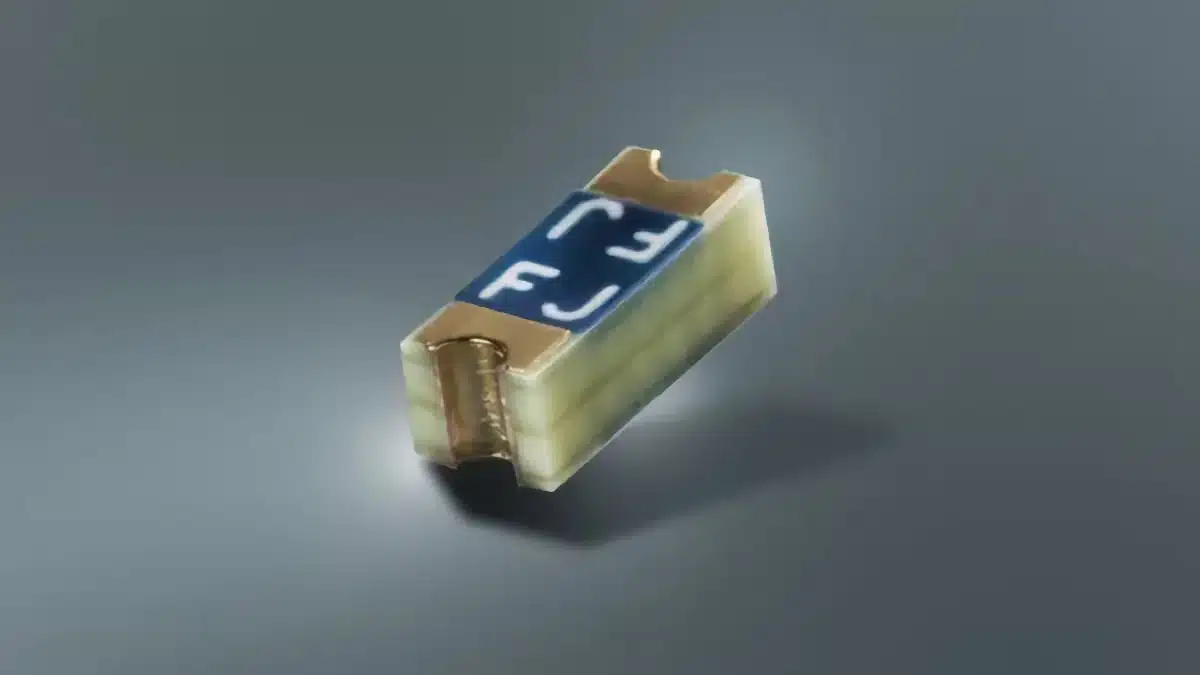
SCHURTER’s USE 2410 is a quick-acting, wire-in-air surface‑mount fuse in the compact 2410 footprint, designed for both AC and DC mains-related applications.

It combines a high breaking capacity and robust mechanical design with AEC‑Q200 testing, making it attractive for industrial, automotive and other demanding environments.

RelatedPosts

SCHURTER Introduces PPTC Resettable Overcurrent Protection for Compact Electronics

SCHURTER Buys Biaodi to Boost High-Voltage Protection Portfolio

SCHURTER Releases SMT Micro Switch for Compact HMIs

Key features and benefits

The USE 2410 fuse targets designers who need compact overcurrent protection with mains-compliant ratings and high reliability.

  • Surface-mount quick‑acting F fuse in 2410 footprint
  • Voltage ratings: 125–250 VAC and 86–125 VDC
  • Breaking capacity up to 200 A
  • Rated current range from 0.6 A to 10 A
  • Temperature range from -55 °C to 125 °C
  • Lead-free design, compliant with RoHS and REACH
  • Tested according to AEC‑Q200, suitable for automotive‑grade designs
  • UL and VDE approvals (according to manufacturer)
  • Housing material UL 94V‑0 (fiber‑reinforced plastic)
  • Gold‑plated copper terminals
  • Sealed construction, resistant against typical potting compounds
  • Reflow solderable for standard SMT assembly processes

From a practical engineering perspective, the combination of 2410 size and up to 250 VAC rating allows designers to replace larger through‑hole or cartridge fuses in space‑constrained designs. The extended operating temperature range improves reliability in harsh environments such as under‑hood automotive, industrial cabinets or tightly packed LED drivers.

Wire-in-air concept and mechanical robustness

The USE 2410 uses an innovative melting wire technology in a wire‑in‑air configuration rather than a traditional fuse link buried in bulk material. This construction:

  • Supports precise, rapid opening under overload and short‑circuit conditions
  • Minimizes the risk of internal solder joint fatigue, as there are no internal solder joints
  • Enhances vibration resistance and robustness, especially in mobile and automotive applications

For mobile, transport and industrial equipment subject to shock and vibration, the absence of internal solder joints helps mitigate common failure modes such as cracked joints or drift in electrical characteristics over lifetime.

Typical applications

The USE 2410 is intended for a wide range of AC and DC applications where compact, fast‑acting overcurrent protection is required.

Typical use cases include:

  • Battery‑operated systems (portable instruments, battery management units, DC power stages)
  • LED drivers and electronic ballasts (primary and secondary side overcurrent protection)
  • Medical and industrial equipment (auxiliary supplies, control boards, I/O modules)
  • Switched‑mode power supplies and adapters (primary mains input and secondary DC outputs)
  • White goods and household appliances (control boards, motor drives, auxiliary loads)
  • Automotive electronics (ECUs, DC/DC converters, body electronics)
  • Aerospace and other transport applications requiring robust, vibration‑resistant SMT fuses

In automotive designs, the AEC‑Q200 testing and the manufacturer’s IATF 16949 background mean the device can be considered for many non‑safety‑critical ECU protection roles, provided the system‑level safety and derating guidelines are respected. In industrial and medical equipment, the sealed construction and wide temperature range help when potting or conformal coating is used for increased insulation or environmental protection.

Technical highlights

From a component selection perspective, several parameters are particularly relevant.

Electrical ratings

  • Voltage:
    • 125–250 VAC (mains‑related AC applications)
    • 86–125 VDC (DC buses and battery systems in this range)
  • Current range: 0.6–10 A (according to manufacturer datasheet)
  • Breaking capacity: up to 200 A

In practice, the 250 VAC rating with 200 A breaking capacity allows the fuse to safely interrupt high fault currents typical of low‑impedance mains or DC bus systems, when coordinated with upstream protection and PCB trace design. The wide current range supports both low‑power logic rails and higher‑current sections such as LED strings, DC motors or power supply outputs.

Thermal and environmental performance

  • Operating temperature range: -55 °C to 125 °C
  • Housing and terminals:
    • Fiber‑reinforced plastic housing, UL 94V‑0 rated
    • Gold‑plated copper terminals

The extended temperature range allows the fuse to be placed close to heat sources such as power semiconductors, transformers or resistors, while still maintaining predictable behavior when properly derated. Gold‑plated terminations improve solderability and long‑term contact reliability, which is valuable in high‑humidity or corrosive environments.

Construction and standards

  • Wire‑in‑air melting wire technology for precise, fast tripping
  • No internal solder joints for improved shock and vibration resistance
  • Sealed construction resistant to common potting compounds
  • Tested to AEC‑Q200 (component qualification standard widely used in automotive)
  • Conformity to UL, VDE, RoHS and REACH (according to manufacturer)

For designers, the AEC‑Q200 qualification means the component has been subjected to a standardized set of environmental, mechanical and electrical tests, making it easier to justify its use in automotive and other high‑reliability applications. The UL 94V‑0 housing flammability rating is often required by safety standards and internal corporate design rules.

Design-in notes for engineers

When designing in the USE 2410, there are several practical points to consider.

Electrical coordination

  • Select the fuse current rating so that it does not open under normal operating and inrush conditions, but clears reliably under fault. Use the time‑current characteristics from the datasheet rather than relying on nominal current alone.
  • Check the maximum prospective short‑circuit current in the application and confirm that it is within the 200 A breaking capacity at the relevant system voltage.
  • Ensure coordination with upstream protection (circuit breakers, mains fuses) and downstream copper traces so that in a fault the fuse clears before PCB damage or excessive heating occurs.

For applications with strong inrush (for example, capacitive input power supplies or LED drivers), it may be necessary to implement inrush limiting or adjust the fuse rating while still meeting safety and reliability targets.

Layout and thermal aspects

  • Use PCB land patterns recommended in the manufacturer datasheet for the 2410 footprint to ensure proper solder fillets and mechanical stability.
  • Place the fuse away from extreme hot spots where possible; if it must be near hot components, apply thermal derating based on the datasheet curves and the ambient inside the enclosure.
  • Consider creepage and clearance distances around the fuse and associated traces when operating at mains voltages, in accordance with relevant safety standards.

In potted or conformally coated assemblies, the sealed design of the USE 2410 helps maintain performance, but it is still important to verify that the chosen compound and process do not excessively modify the thermal environment.

Reliability and qualification

  • For automotive and other high‑reliability designs, the AEC‑Q200 testing background is useful, but final qualification should follow the end‑customer or OEM requirements.
  • Run board‑level tests (thermal cycling, vibration, surge/overload tests) with the selected fuse rating to confirm behavior under real system conditions.
  • For global products, verify that the specific catalog part number used has the required UL and VDE approvals for the target markets.

By aligning fuse selection, PCB layout and system‑level protection strategy, the USE 2410 can deliver compact, reliable overcurrent protection in a wide range of AC and DC applications.

Source

This article is based on information provided by SCHURTER in their official press release and associated product documentation for the USE 2410 surface‑mount fuse series.

References

  1. SCHURTER press release – Surface-Mount Fuse USE 2410: Wire-in-air redefined
  2. SCHURTER USE 2410 datasheet

Related

Recent Posts

Littelfuse Announced TVS Diodes for 48 V Automotive Systems

10.7.2026
13

RF Filters and Passive Components Enabling the 7 Missile RF Subsystems

9.7.2026
36

Coilcraft Releases High-Current Ferrite Beads for CISPR 25 EMC compliance

8.7.2026
36

Vishay Unveils Multi-Turn Position Sensor for Harsh Industrial Environments

7.7.2026
29

YAGEO Introduces Automotive MOV Surge Protection Varistor

7.7.2026
25

TDK Releases Compact SMD Gate Drive Transformers for xEV

7.7.2026
35

Molex Unveils Automotive Ethernet Connectors for Next‑Gen SDV Architectures

2.7.2026
41

TAIYO YUDEN Introduced Hybrid Aluminum Capacitors for 48V Automotive Power Supplies

2.7.2026
71

YAGEO Announces July 2026 Capacitor Price Increase

1.7.2026
695

Upcoming Events

Jul 14
16:00 - 17:00 CEST

EMC Design Essentials: Mastering Varistors and Common Mode Chokes

Jul 21
16:00 - 17:00 CEST

Safety by design: X and Y Interference suppression capacitors for power line filters

Jul 28
8:00 - 11:00 CEST

Post Procurement Testing of EEE Components for LEO Space Applications

View Calendar

Popular Posts

  • Boost Converter Design and Calculation

    0 shares
    Share 0 Tweet 0
  • Buck Converter Design and Calculation

    0 shares
    Share 0 Tweet 0
  • Flyback Converter Design and Calculation

    0 shares
    Share 0 Tweet 0
  • LLC Resonant Converter Design and Calculation

    0 shares
    Share 0 Tweet 0
  • YAGEO Announces July 2026 Capacitor Price Increase

    0 shares
    Share 0 Tweet 0
  • MLCC and Ceramic Capacitors

    0 shares
    Share 0 Tweet 0
  • Earthing Systems and IEC Classification Explained

    0 shares
    Share 0 Tweet 0
  • Nvidia Vera Rubin: Why One AI Rack Needs So Many More MLCC Capacitors

    0 shares
    Share 0 Tweet 0
  • MLCCs in the Age of AI: Q2 2026 Market Tightness

    0 shares
    Share 0 Tweet 0
  • Dual Active Bridge (DAB) Topology

    0 shares
    Share 0 Tweet 0

Newsletter Subscription


Passive Components Blog

© EPCI - Leading Passive Components Educational and Information Site

  • Home
  • Privacy Policy
  • EPCI Membership & Advertisement
  • About

No Result
View All Result
  • Home
  • Knowledge Blog
  • Dossiers
  • PCNS

© EPCI - Leading Passive Components Educational and Information Site

This website uses cookies. By continuing to use this website you are giving consent to cookies being used. Visit our Privacy and Cookie Policy.
Go to mobile version