Passive Components Blog
No Result
View All Result
  • Home
  • NewsFilter
    • All
    • Aerospace & Defence
    • Antenna
    • Applications
    • Automotive
    • Capacitors
    • Circuit Protection Devices
    • electro-mechanical news
    • Filters
    • Fuses
    • Inductors
    • Industrial
    • Integrated Passives
    • inter-connect news
    • Market & Supply Chain
    • Market Insights
    • Medical
    • Modelling and Simulation
    • New Materials & Supply
    • New Technologies
    • Non-linear Passives
    • Oscillators
    • Passive Sensors News
    • Resistors
    • RF & Microwave
    • Telecommunication
    • Weekly Digest

    TDK Extends SMT Gate Drive Transformers to 1000 V

    Non-Linear MLCC Class II Capacitor Measurements Challenges

    Researchers Demonstrated HfO Anti-Ferroelectric Flexible Capacitors

    Connector Industry Achieves Double-Digit Growth

    Stackpole Unveils Metal Element High Current Chip Jumpers

    Common Mistakes in Flyback Transformer Specs

    Vishay Releases Miniature SMD Trimmers for Harsh Environments

    Würth Elektronik Releases Push-Button and Main Switches

    Littelfuse Unveils High-Precision TMR Angle Magnetic Sensors

    Trending Tags

    • Ripple Current
    • RF
    • Leakage Current
    • Tantalum vs Ceramic
    • Snubber
    • Low ESR
    • Feedthrough
    • Derating
    • Dielectric Constant
    • New Products
    • Market Reports
  • VideoFilter
    • All
    • Antenna videos
    • Capacitor videos
    • Circuit Protection Video
    • Filter videos
    • Fuse videos
    • Inductor videos
    • Inter-Connect Video
    • Non-linear passives videos
    • Oscillator videos
    • Passive sensors videos
    • Resistor videos

    Non-Linear MLCC Class II Capacitor Measurements Challenges

    Percolation Phenomenon and Reliability of Molded Power Inductors in DC/DC converters

    Root Causes and Effects of DC Bias and AC in Ceramic Capacitors

    How to Calculate the Output Capacitor for a Switching Power Supply

    Switched Capacitor Converter Explained

    Understanding Inductor Dot Markings and Their Application in LTspice

    Accelerating Full Bridge LLC Resonant Converter Design with Frenetic AI

    Understanding Switched Capacitor Converters

    Coupled Inductors Circuit Model and Examples of its Applications

    Trending Tags

    • Capacitors explained
    • Inductors explained
    • Resistors explained
    • Filters explained
    • Application Video Guidelines
    • EMC
    • New Products
    • Ripple Current
    • Simulation
    • Tantalum vs Ceramic
  • Knowledge Blog
  • Suppliers
    • Who is Who
  • Events
No Result
View All Result
Passive Components Blog
No Result
View All Result

New flip-chip resistors offer ultra-stable performance and improved ruggedness

23.2.2016
Reading Time: 2 mins read
A A

source: Vishay VPG news

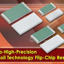
Latest from VPG is the Vishay Foil Resistors FRFC Series, a new family of ultra-high-precision flip chip resistors based on the market-leading Z1 Foil Technology. The FRFC Series delivers remarkable load life stability of 50ppm, better withstanding to higher temperatures, and better moisture resistance than previous-generation foil resistors. Compared with surface-mount chips with wraparound terminations, the flip chip configuration of the FRFC Series provides PCB space savings of more than 35%.

RelatedPosts

TDK Extends SMT Gate Drive Transformers to 1000 V

Non-Linear MLCC Class II Capacitor Measurements Challenges

Researchers Demonstrated HfO Anti-Ferroelectric Flexible Capacitors

The FRFC Series owes its high-performance characteristics to a resistive element based on Z1 Foil Technology, a solid alloy that is matched to the ceramic substrate with polyimide bonding to enable a uniform thickness of the bond line, superior adhesion strength, and improved resistance to moisture. Virtually insensitive to destabilizing factors, the FRFC Series features a temperature coefficient of resistance (TCR) or ± 0.2 ppm/C (-55°C to +125C, +25C ref), ESD immunity to 25kV or more, and noise-free operation. Its power rating is 750mW at +70°C, a 25% improvement over the VFCP Series, which is already a superior product in the high-precision resistors industry. The FRFC Series flip chip resistors are offered in the 0805, 1206, 1506, 2010, and 2512 case sizes, with power TCR (ΔR due to self-heating) of 5ppm at rated power and tight tolerances to ±0.01%.

“The FRFC Series devices provide designers with the most stable resistors available today — allowing them to achieve new benchmark levels in performance,” said Jacky Acoca, director of sales and marketing, Vishay Foil Resistors. “In addition to saving on board space, the devices’ flip chip terminations increase reliability by providing better strain relief to eliminate cracked substrates and board delamination.”

The FRFC Series flip chip resistors are optimized for a wide range of high-precision industrial, telecommunications, medical, and laboratory applications, including bridge networks, gyro navigational controls, pressure sensors, standards and decade boxes, process controls, weighing systems, electron beams, and automatic test equipment.

The new resistors offer a resistance range from 5ohm to 125kohm with any conceivable ohmic value within this range — out to six digits – available with no additional cost or lead time effect. They feature a rise time of 1 ns with effectively no ringing; a thermal stabilization time of <1s (within 10ppm of steady state value); current noise of 0.01μVrms/V of applied voltage (<-40dB); and a voltage coefficient of <0.1ppm/V. The RoHS-compliant FRFC Series resistors offer a non-inductive (<0.08 μH), non-capacitive design and are available in matched sets on request, says the company.

Related

Recent Posts

TDK Extends SMT Gate Drive Transformers to 1000 V

20.8.2025
12

Stackpole Unveils Metal Element High Current Chip Jumpers

19.8.2025
10

Vishay Releases Miniature SMD Trimmers for Harsh Environments

14.8.2025
12

Littelfuse Unveils High-Precision TMR Angle Magnetic Sensors

13.8.2025
9

Stackpole Extends Voltage of High Temp Chip Resistors

13.8.2025
11

High Voltage MLCCs Meeting the Growing Demand for Efficiency in Power Conversion

12.8.2025
126

Bourns Releases High Power High Ripple Chokes

8.8.2025
34

KYOCERA AVX Releases Hermaphroditic WTW and WTB Connectors

8.8.2025
15

TDK Releases Compact Polypropylene Film Capacitors for Resonant Topologies

7.8.2025
34

Würth Elektronik Offers Accessory Humidity Sensor Filter Cap

6.8.2025
10

Upcoming Events

Aug 27
17:00 - 18:00 CEST

Capacitor Assemblies for High-Power Circuit Designs

Sep 3
15:30 - 17:30 CEST

How to Choose Your Magnetic Supplier

Sep 16
17:00 - 18:00 CEST

EMI Shielding Challenges

Sep 22
September 22 @ 13:00 - September 25 @ 15:15 EDT

Pre Cap Visual Inspection per Mil-Std-883 (TM 2017)

Sep 30
September 30 @ 12:00 - October 2 @ 14:00 EDT

MIL-Std-883 TM 2010

View Calendar

Popular Posts

  • Buck Converter Design and Calculation

    0 shares
    Share 0 Tweet 0
  • Boost Converter Design and Calculation

    0 shares
    Share 0 Tweet 0
  • Flyback Converter Design and Calculation

    0 shares
    Share 0 Tweet 0
  • LLC Resonant Converter Design and Calculation

    0 shares
    Share 0 Tweet 0
  • What is a Dielectric Constant and DF of Plastic Materials?

    4 shares
    Share 4 Tweet 0
  • Ripple Current and its Effects on the Performance of Capacitors

    3 shares
    Share 3 Tweet 0
  • Dual Active Bridge (DAB) Topology Explained

    0 shares
    Share 0 Tweet 0
  • How to Design an Inductor

    0 shares
    Share 0 Tweet 0
  • Core Materials, Permeability and Their Losses

    0 shares
    Share 0 Tweet 0
  • MLCC Case Sizes Standards Explained

    0 shares
    Share 0 Tweet 0

Newsletter Subscription


Passive Components Blog

© EPCI - Leading Passive Components Educational and Information Site

  • Home
  • Privacy Policy
  • EPCI Membership & Advertisement
  • About

No Result
View All Result
  • Home
  • Knowledge Blog
  • Premium Suppliers

© EPCI - Leading Passive Components Educational and Information Site

This website uses cookies. By continuing to use this website you are giving consent to cookies being used. Visit our Privacy and Cookie Policy.
Go to mobile version