Passive Components Blog
No Result
View All Result
  • Home
  • NewsFilter
    • All
    • Aerospace & Defence
    • Antenna
    • Applications
    • Automotive
    • Capacitors
    • Circuit Protection Devices
    • electro-mechanical news
    • Filters
    • Fuses
    • Inductors
    • Industrial
    • Integrated Passives
    • inter-connect news
    • Market & Supply Chain
    • Market Insights
    • Medical
    • Modelling and Simulation
    • New Materials & Supply
    • New Technologies
    • Non-linear Passives
    • Oscillators
    • Passive Sensors News
    • Resistors
    • RF & Microwave
    • Telecommunication
    • Weekly Digest

    Samtec Expands Connector Severe Environment Testing Offering

    Silicon Capacitors Market: Shaping the Foundation for Next-Gen Miniaturization Electronics

    YAGEO Releases Compact Coupled Inductors for High-Density VR Designs

    Enhancing Energy Density in Nanocomposite Dielectric Capacitors

    Advances in the Environmental Performance of Polymer Capacitors

    Vishay Releases DLA Tantalum Polymer Capacitors for Military and Aerospace

    Vishay Expanded Inductor Portfolio With More Than 2000 Stock Items 

    Paumanok Releases Capacitor Foils Market Report 2025-2030

    Modelithics Welcomes CapV as a Sponsoring MVP

    Trending Tags

    • Ripple Current
    • RF
    • Leakage Current
    • Tantalum vs Ceramic
    • Snubber
    • Low ESR
    • Feedthrough
    • Derating
    • Dielectric Constant
    • New Products
    • Market Reports
  • VideoFilter
    • All
    • Antenna videos
    • Capacitor videos
    • Circuit Protection Video
    • Filter videos
    • Fuse videos
    • Inductor videos
    • Inter-Connect Video
    • Non-linear passives videos
    • Oscillator videos
    • Passive sensors videos
    • Resistor videos

    Connector PCB Design Challenges

    Efficient Power Converters: Duty Cycle vs Conduction Losses

    Ripple Steering in Coupled Inductors: SEPIC Case

    SEPIC Converter with Coupled and Uncoupled Inductors

    Coupled Inductors in SEPIC versus Flyback Converters

    Non-Linear MLCC Class II Capacitor Measurements Challenges

    Percolation Phenomenon and Reliability of Molded Power Inductors in DC/DC converters

    Root Causes and Effects of DC Bias and AC in Ceramic Capacitors

    How to Calculate the Output Capacitor for a Switching Power Supply

    Trending Tags

    • Capacitors explained
    • Inductors explained
    • Resistors explained
    • Filters explained
    • Application Video Guidelines
    • EMC
    • New Products
    • Ripple Current
    • Simulation
    • Tantalum vs Ceramic
  • Knowledge Blog
  • Suppliers
    • Who is Who
  • Events
No Result
View All Result
Passive Components Blog
No Result
View All Result

Power Over Ethernet (PoE) and PoE+

20.9.2021
Reading Time: 3 mins read
A A

Definition
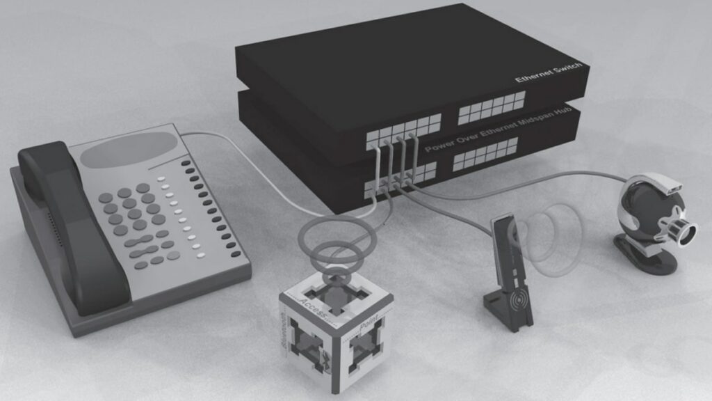
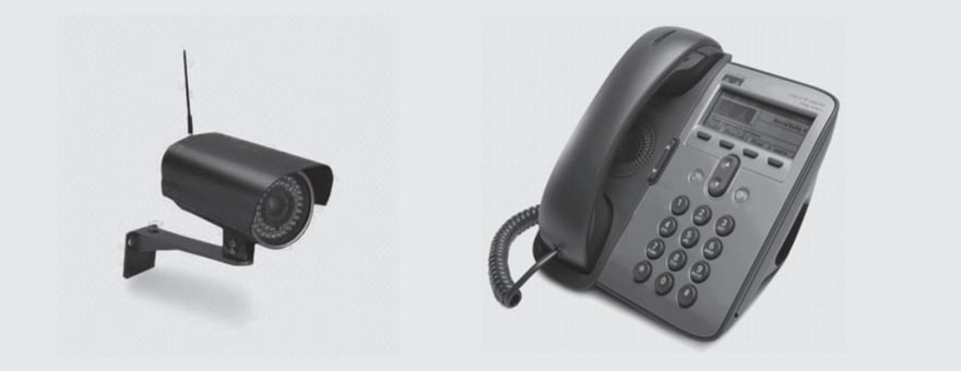
Power Over Ethernet (POE) technology allows VoIP phones, WLAN access, IP camera … to receive power as well as data over existing LAN cabling without modifying the existing system.

Establishment of an international standard, IEEE802.3af allows an explosion of POE installation all over the world, which was not possible while old proprietary standards were existing together. The cost of adding power supplies to Ethernet switches is getting smaller and smaller. Figure 2.159 shows a typical POE installation.

RelatedPosts

Polymer Materials and Processing

What is RF Connector

Connector Materials and Processes

Fig. 2.159: Typical POE installation

Today, most electronic applications require both data connectivity and power supply. The most familiar example is telephone which is powered via the same twisted pair that carries the voice since its invention. Did you ever plug your telephone to power before they become hand free?! Of course not so the aim of POE standard is to standardize how to do the same with Ethernet devices without modifying the communication protocol.

There were many technical constraints. A complete recognition protocol had to be defined to detect whether connected systems could receive power (without damaging them), classify their power ratings, and define the way of transmitting voltage and current.

Classification and Applications
This article does not aim to go into too much detail about POE but the attached classification gives the main characteristics of the POE & POE+ standards (POE+ being able to carry more power, up to 25.5 W like for a bigger IP camera with zoom …)

Tab. 2.18: POE classification
Fig. 2.160: Typical POE applications (left: IP camera/right: IP phone)

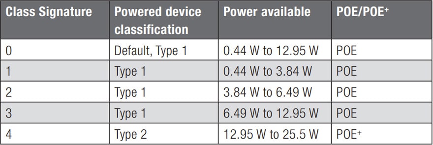
The IEEE standards are 802.3af and 802.3at respectively for PoE or PoE+.

Fig. 2.161: Synopsis of a POE system

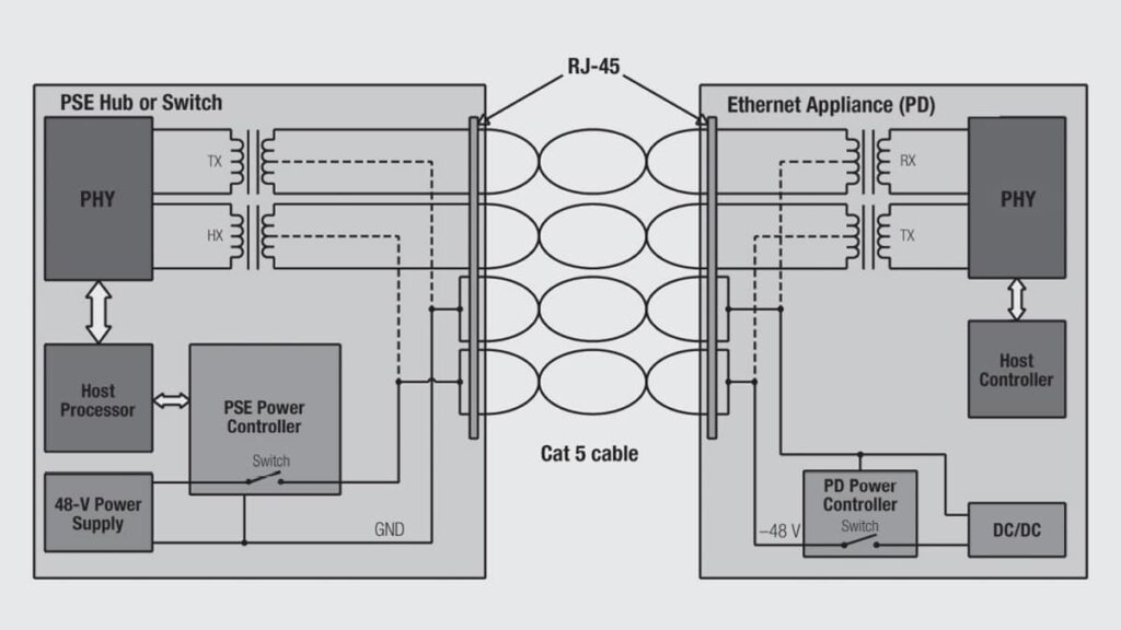
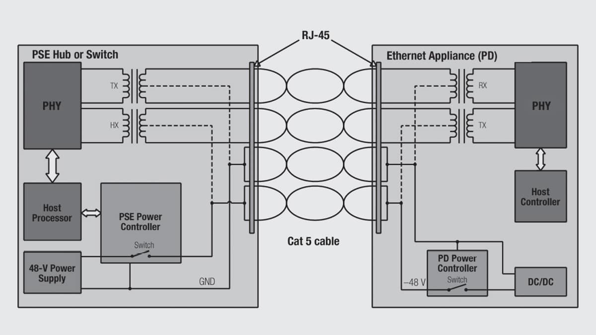
PSE: (Power Sourcing Equipment) the device that provides power.
PD: (Power Device) this is the device that receives power.

Usually, the distribution is as follows:

PHY side: TD+/–, RD+/–, PHY ground, LED pins (as LED are driven by the PHY)
Cable side: Power pins (PoE), RJ45 pins.

What about modular jacks, what does it imply on this respect?
The key point is the insulation which is carefully controlled and the interface must withstand 1500 Vrms 1 min. PHY side and cable side (remember Figure 2.155) must be insulated from each other.

The distance between RJ45 pins and between RJ45 pins & shielding must be sufficient to stand this voltage. In this case above 1.4mm.

Problems comes often from the LED pins that are in general too close to the shielding.

Summary
To stand POE standard, pins must always have a minimum distance of 1.4 mm between each other and with the shielding too. Special care must be on LED pins which are often too close to the shielding.

A connector does not have absolutely to be used with transformer to be POE compatible (a standard connector without LED should fit) but it is often necessary (for the LED one) since transformer connector designer often included the POE parameter in their concept (much more than the non-filtered one which were developed earlier)

Related

Source: Wurth elektronik

Recent Posts

Connector PCB Design Challenges

3.10.2025
34

Non-Magnetic Interconnects

23.4.2025
27

10 Tips for Ensuring Reliability of Discrete Wire Assemblies

20.2.2025
56

Polymer Materials and Processing

11.8.2025
55

Basic PCB Technology Overview

1.7.2025
24

What is RF Connector

17.12.2024
14

Creepage and Clearance of Connector

25.7.2025
24

Microwave Multi Line Connectors Mounting and Handling Precautions

11.8.2025
3

BASIC PCB Design Rules – Layout

1.7.2025
35

MEMR RF Relay for Space Compact Redundancy Ring

17.12.2024
4

Upcoming Events

Oct 14
16:00 - 17:00 CEST

Smart Sensors, Smarter AI: Building Reliable Edge Systems

Oct 17
12:00 - 14:00 EDT

External Visual Inspection per MIL-STD-883 TM 2009

Oct 20
October 20 - October 23

Digital WE Days 2025 – Virtual Conference

Oct 21
October 21 @ 12:00 - October 23 @ 14:15 EDT

Space and Military Standards for Hybrids and RF Microwave Modules

Oct 28
8:00 - 15:00 CET

Power Up Your Design: SN6507 and the Ready-to-Use Development Kit

View Calendar

Popular Posts

  • Buck Converter Design and Calculation

    0 shares
    Share 0 Tweet 0
  • Boost Converter Design and Calculation

    0 shares
    Share 0 Tweet 0
  • Flyback Converter Design and Calculation

    0 shares
    Share 0 Tweet 0
  • LLC Resonant Converter Design and Calculation

    0 shares
    Share 0 Tweet 0
  • What is a Dielectric Constant and DF of Plastic Materials?

    4 shares
    Share 4 Tweet 0
  • SEPIC Converter Design and Calculation

    0 shares
    Share 0 Tweet 0
  • Dual Active Bridge (DAB) Topology Explained

    0 shares
    Share 0 Tweet 0
  • Ripple Current and its Effects on the Performance of Capacitors

    3 shares
    Share 3 Tweet 0
  • MLCC and Ceramic Capacitors

    0 shares
    Share 0 Tweet 0
  • Flying Capacitors Explained

    0 shares
    Share 0 Tweet 0

Newsletter Subscription


Passive Components Blog

© EPCI - Leading Passive Components Educational and Information Site

  • Home
  • Privacy Policy
  • EPCI Membership & Advertisement
  • About

No Result
View All Result
  • Home
  • Knowledge Blog
  • Premium Suppliers

© EPCI - Leading Passive Components Educational and Information Site

This website uses cookies. By continuing to use this website you are giving consent to cookies being used. Visit our Privacy and Cookie Policy.
Go to mobile version