


KYOCERA AVX issues a white paper investigating radiation harness and radiation tolerance of tantalum capacitors and ceramic capacitors.
KYOCERA AVX’s white paper provides insights into the radiation tolerance of tantalum and ceramic capacitors.
Passive electronic components’ radiation hardness is poorly studied. They’re either considered non-sensitive to ionizing environments or not used in radiation-hardened applications. This knowledge gap hinders the adoption of new technologies in space, nuclear, military, and other applications with ionizing radiation, including polymer tantalum capacitors with high energy density, low ESR series resistance, and stable electrical parameters.
To investigate passive electronic components for these applications, focus on ionizing radiation dose and type. Directly ionizing radiation consists of charged particles (e.g., electrons, protons) with sufficient energy to create ionization. Indirectly ionizing radiation includes particles without charge (e.g., neutrons, photons) with higher penetrability due to lower interaction probability.
In a 2023 article, Kyocera AVX investigated the radiation tolerance of molded SMD tantalum capacitors with both conventional MnO₂ and polymer cathodes. The capacitors showed excellent radiation tolerance in terms of capacitance (CAP), dissipation factor (DF), equivalent series resistance (ESR), and direct current leakage (DCL) after irradiation with a 20 MeV photon beam at a dose rate of 1.44 kGy, up to a total dose of 4.5 kGy [1].
This article investigates the radiation tolerance of passive components across multiple high-reliability capacitor series manufactured by Kyocera AVX, including hermetically sealed polymer tantalum capacitors, MIL-PRF-39006/33 wet tantalum capacitors, and MIL-PRF-32535 MLCCs with X7R dielectric.
HERMETICALLY SEALED POLYMER TANTALUM CAPACITORS
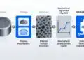
Hermetically sealed polymer tantalum capacitors are similar to standard SMD polymer tantalum capacitors. They consist of a sintered tantalum pellet with a high surface area. The tantalum pentoxide dielectric is formed by applying DC voltage to pellets submerged in an acidic electrolyte, with thickness proportional to the voltage. The polymer cathode terminal is prepared by in-situ polymerization or depositing polymer dispersions. PEDOT is the most commonly used conductive polymer due to its strong contact with the dielectric, high conductivity, and temperature stability. Hermetically sealing these capacitors in a ceramic case prevents oxidation and humidity degradation of the polymer cathode.
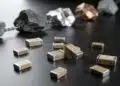
Hermetically sealed polymer tantalum capacitors offer low ESR, high energy density, voltages up to 125 V, and stable electrical parameters. They are typically used in power supplies and pulse power in aerospace and defense. [2,3]
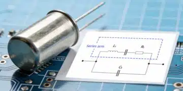
Wet tantalum capacitors, similar to SMD polymer tantalum capacitors, consist of a sintered tantalum pellet with an embedded tantalum wire. The pellet serves as the positive electrode (anode), while the negative electrode (cathode) is an extremely high surface area material on the inner surface of a tantalum can in contact with a liquid electrolyte. The electrolyte connects the cathode to the dielectric layer, forming the complete cathode. All components are hermetically sealed within the can, with external anode and cathode leads connected to the embedded anode wire and the can, respectively.
Wet tantalum capacitors have been used for years in high-energy storage applications requiring volumetric efficiency and high reliability, including industrial petroleum exploration, military avionics, and aerospace applications. The Kyocera AVX MIL-PRF-39006/33 meets the requirements for wet tantalum capacitors in military applications.
CERAMIC CAPACITORS WITH X7R DIELECTRIC
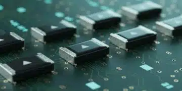
Multilayer ceramic capacitors (MLCCs) consist of a monolithic ceramic block with offset, interleaved electrodes embedded in the ceramic dielectric. Class I MLCCs are temperature-compensating, while Class II MLCCs are temperature-stable and suitable for general applications. The X7R dielectric, a common Class II formulation, has a capacitance variation of ±15% over a temperature range of -55°C to +125°C. Class II MLCC capacitance also varies with applied voltage and frequency. [5]
Kyocera AVX offers DLA-approved MIL-PRF-32535 X7R dielectric MLCCs in case sizes from 0402 to 2220, with capacitance/voltage ratings ranging from 2.2 nF to 22 µF and 16 to 100 V. These capacitors expand the CV range compared to standard MIL specifications while maintaining high reliability. Typical applications include science exploration, earth observation, communication, satellite launchers, and military/land/air-based applications. [6]
RADIATION TESTING
For irradiation testing, the Czech Academy of Sciences (CAS) in Prague operated a Microtron MT25.
The MT25 is a cyclic electron accelerator with a Kapitza resonator, capable of energizing electrons in clusters at levels scaled by 1 MeV steps from 6 MeV to 25 MeV. Electrons are accelerated by an RF electric field of constant amplitude and frequency in a uniform magnetic field. [7]
Unlike cyclotrons that produce protons, microtrons accelerate electrons, which are much lighter. Although electrons can reach high kinetic energies similar to protons, their interactions with matter differ due to mass, charge, and atomic behavior. The lower mass of electrons imparts less energy on irradiated samples, causing chemical changes without nuclear reactions. This makes it easier to achieve homogeneous irradiation and prevents radioactivity in the device under test (DUT). Microtrons also offer excellent control and configurability of the total radiation dose.
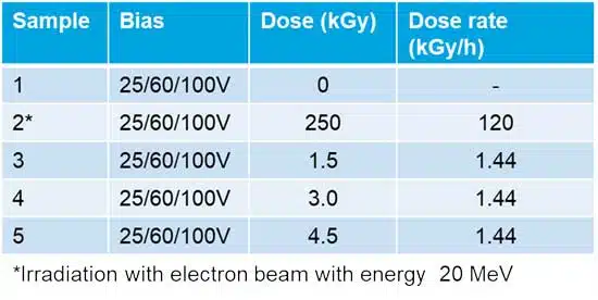
The irradiation used a photon beam (Bremsstrahlung) with an energy of 20 MeV, produced by decelerating electrons through a tungsten target behind the exit window. The dose rate was 1.44 kGy/hour.
An extreme irradiation dose was used with an electron beam from the microtron, also at 20 MeV, with a dose rate of 120 kGy/hour.
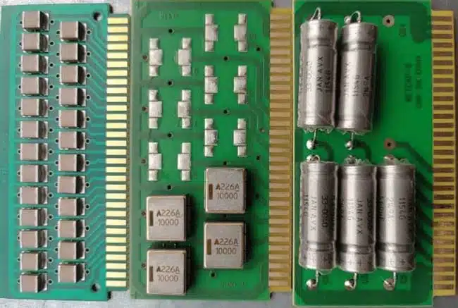
Hermetically sealed tantalum polymer capacitors (TCH9226M100W0150), wet tantalum capacitors (M39006/33-0040), and two ceramic capacitors with X7R dielectric were mounted on a custom FR5 PCB array for irradiation and characterization (Fig.1). Each group was exposed to three different radiation doses from a photon beam while the rated bias voltage was applied. All groups were also tested with an extreme irradiation dose from the electron beam, with the rated bias voltage applied, as shown in Fig. 2.
A 24-hour, 125°C high-temperature annealing period was included as the final stage in the testing cycle. This step, common in standards for irradiated components (such as MIL-STD 750-1, MIL-STD 883, ESCC 25100, and ESCC 22900), may help dissipate excitation electrons induced in the dielectric material by radiation.
After each radiation dose, the bulk capacitance, ESR, dissipation factor (DF), and DC leakage current (DCL) were measured across the devices in the array. For hermetically sealed polymer tantalum capacitors, bulk capacitance and DF were measured at 120 Hz with a 2 V bias and a 1 V AC measurement current; ESR was measured at 100 kHz with a 2 V bias and a 1 V AC measurement current; and DCL was measured with a 1 kΩ resistor in series at room temperature (RT), with readings taken after 300 seconds of applying the rated voltage.
For wet tantalum capacitors, bulk capacitance, DF, and ESR were measured at 120 Hz with a 2 V bias and a 1 V AC measurement current; DCL was measured with a 1 kΩ resistor in series at RT, with readings taken after 300 seconds of applying the rated voltage.
For ceramic capacitors with X7R dielectric, bulk capacitance, DF, and ESR were measured at 1 kHz with a 2 V bias and a 0.5 V AC measurement current; DCL was measured with a 10 kΩ resistor in series at RT, with readings taken after 300 seconds of applying the rated voltage.
By observing changes in these parameters across different radiation doses, the resilience of each device under ionizing radiation can be assessed.
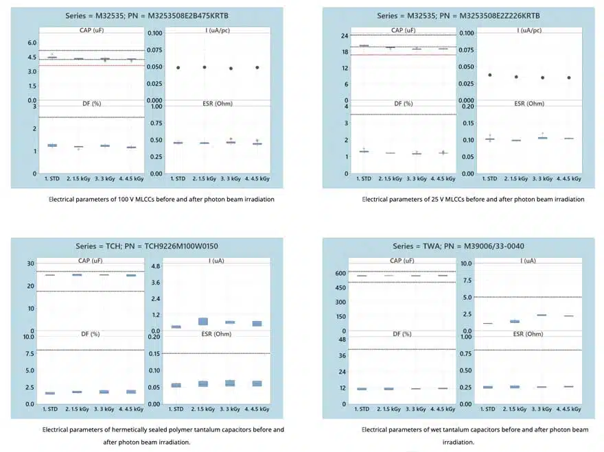
RESULTS OF TESTING | PHOTON BEAM IRRADIATION
A slight decrease in capacitance was observed for both the 25 V and 100 V MLCCs after photon irradiation at doses ranging from 1.5 to 4.5 kGy (Figures 3). The capacitance change was -7.5% for the 100 V parts and -10% for the 25 V parts. Despite the decrease, the capacitance remained within the permitted -15% change specified in MIL-PRF-32535.
A slight increase in leakage current was noted in the wet tantalum capacitors, rising by approximately 1 µA to a total of around 2 µA (Figure 3). This increase had no relevant impact on the performance of the parts and remained well below the 5 µA specification limit.
No other significant changes were observed in the measured parameters for any of the tested capacitors following photon beam irradiation at doses up to 4.5 kGy. The hermetically sealed polymer tantalum capacitors exhibited excellent stability across all measured parameters under photon beam irradiation up to this dose level (Figure 3).
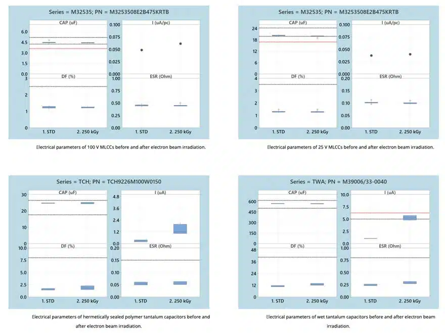
RESULTS OF TESTING | ELECTRON BEAM IRRADIATION
Electron beam irradiation at a dose of 250 kGy caused an increase in DCL across all tested capacitors. The DCL of both MLCC part numbers remained below 70 nA after testing (Figure 4.).
In the hermetically sealed polymer tantalum capacitors, DCL increased by approximately 1 µA. Following testing, the DCL remained within the specification limit of 220 µA for these parts (Figure 4.).
For wet tantalum capacitors, the highest observed DCL increase from electron beam irradiation was from 1 µA to 5.1 µA, exceeding the initial specification limit of 5 µA in some parts. MIL-PRF-39006/33B permits a 125% increase in DCL for reliability tests, equating to 6.25 µA, which was not exceeded (Figure 4).
DISCUSSIONS AND FUTURE CONSIDERATIONS
X7R dielectric MLCCs showed a decrease in capacitance after photon beam irradiation at doses up to 4.5 kGy and electron beam irradiation at 250 kGy, but this remained within reliability limits. DCL increased negligibly under electron beam irradiation. ESR and DF parameters remained stable. These results align with previous findings, supporting their use in military and space applications with radiation exposure.
Hermetically sealed tantalum capacitors showed excellent radiation stability across electrical parameters after photon beam irradiation at 4.5 kGy and electron beam irradiation at 250 kGy, similar to molded SMD tantalum polymer capacitors [1]. Their high volumetric efficiency, low ESR, long lifetime, and self-healing properties make them suitable for military and space applications with radiation exposure.
Wet tantalum capacitors also showed excellent stability in electrical parameters after photon beam irradiation at 4.5 kGy. DCL slightly increased after electron beam irradiation at 250 kGy but remained within reliability limits. Wet tantalum capacitors are recommended for military and space applications with radiation exposure.
The observed DCL changes after the extreme 250 kGy electron beam dose were due to the direct ionizing effect of electron irradiation and its high energy density (dose rate: 120 kGy/hour).
Future testing could measure electrical parameters for conventional MnO₂ tantalum, polymer tantalum, and wet tantalum capacitors during irradiation and study the effects of neutron irradiation. Both tests present unique challenges in testing equipment and radiation safety.
Visit https://www.kyocera-avx.com/products/tantalum/high-reliability/ to learn more about KYOCERA AVX’s tantalum polymer capacitors.
References:
- [1] K. Adamek: Radiation Tolerance of Tantalum Polymer Capacitors. (2023)
- [2] J. Petrzilek, M. Uher, J. Navratil, M. Biler: Polymer Tantalum Capacitors for Advanced High Reliability Applications, SPCD (2016)
- [3] KYOCERA AVX Provided Key Components for the Historic Chandrayaan-3 Lunar Mission. (n.d.). Kyocera AVX. Retrieved August 29, 2024, from https://www.kyocera-avx.com/news/chandrayaan-3-lunar-mission/
- [4] Tantalum WetElectrolytic Capacitors Guide. (n.d.). Kyocera AVX. Retrieved August 29, 2024, from https://www.kyocera-avx.com/docs/techinfo/WetTantalum.pdf
- [5] Surface Mount Ceramic Capacitor Products. (n.d.). Kyocera AVX. Retrieved August 29, 2024, from https://catalogs.kyocera-avx.com/SurfaceMount.pdf
- [6] MIL-PRF-32535 X7R BME Multi-Layer Ceramic Capacitors (MLCC). Kyocera AVX. Retrieved August 29, 2024, from https://www.kyocera-avx.com/products/ceramic-capacitors/surface-mount/militaryaerospace/mil-prf-32535-x7r-bme-mlcc-ceramic-capacitors/
- [7] Microtron MT25. (n.d.). Ústav jaderné fyziky AV ČR. Retrieved November 13, 2022, from http://www.ujf.cas.cz/en/departments/department-of-accelerators/microtron/
- [8] C.L. Hanks, D.J. Hamman: Radiation Effects Design Handbook Section 3. Electrical Insulating Materials and Capacitors. NASA CR-1787. (1971)
Download full paper version in pdf from KYOCERA AVX website here: