Passive Components Blog
No Result
View All Result
  • Home
  • NewsFilter
    • All
    • Aerospace & Defence
    • Antenna
    • Applications
    • Automotive
    • Capacitors
    • Circuit Protection Devices
    • electro-mechanical news
    • Filters
    • Fuses
    • Inductors
    • Industrial
    • Integrated Passives
    • inter-connect news
    • Market & Supply Chain
    • Market Insights
    • Medical
    • Modelling and Simulation
    • New Materials & Supply
    • New Technologies
    • Non-linear Passives
    • Oscillators
    • Passive Sensors News
    • Resistors
    • RF & Microwave
    • Telecommunication
    • Weekly Digest
    Researchers developed a polymer capacitor by combining two cheap, commercially available plastics. The new polymer capacitor makes use of the transparent material — pictured here, with vintage Penn State athletic marks visible through it — to store four times the energy and withstand significantly more heat.  Credit: Penn State

    Penn State Demonstrated Polymer Alloy Capacitor Film with 4× Energy Density up to 250C

    ECIA January 2026 Reports Strong Sales Confidence

    Vishay Unveils Ultra-Compact 0201 Thick Film Chip Resistors

    Würth Elektronik Component Data Live in Accuris

    Coilcraft Releases Automotive Common Mode Chokes

    MLCC Manufacturers Consider Price Increase as AI Demand Outpaces Supply

    YAGEO Extends Antenna Portfolio with Wi‑Fi 6E/7 and Tri‑band GNSS Solutions

    SCHURTER Introduces 2410 SMD Fuse for Robust AC/DC Protection

    TDK Releases High Temp 175C Automotive NTC thermistors

    Trending Tags

    • Ripple Current
    • RF
    • Leakage Current
    • Tantalum vs Ceramic
    • Snubber
    • Low ESR
    • Feedthrough
    • Derating
    • Dielectric Constant
    • New Products
    • Market Reports
  • VideoFilter
    • All
    • Antenna videos
    • Capacitor videos
    • Circuit Protection Video
    • Filter videos
    • Fuse videos
    • Inductor videos
    • Inter-Connect Video
    • Non-linear passives videos
    • Oscillator videos
    • Passive sensors videos
    • Resistor videos

    2026 Power Magnetics Design Trends: Flyback, DAB and Planar

    Enabling Software‑Defined Vehicle Architectures: Automotive Ethernet and Zonal Smart Power

    Calculating Resistance Value of a Flyback RC Snubber 

    One‑Pulse Characterization of Nonlinear Power Inductors

    Thermistor Linearization Challenges

    Coaxial Connectors and How to Connect with PCB

    PCB Manufacturing, Test Methods, Quality and Reliability

    Transformer Behavior – Current Transfer and Hidden Feedback

    Choosing the Right Capacitor: The Importance of Accurate Measurements

    Trending Tags

    • Capacitors explained
    • Inductors explained
    • Resistors explained
    • Filters explained
    • Application Video Guidelines
    • EMC
    • New Products
    • Ripple Current
    • Simulation
    • Tantalum vs Ceramic
  • Knowledge Blog
  • DossiersNew
  • Suppliers
    • Who is Who
  • PCNS
    • PCNS 2025
    • PCNS 2023
    • PCNS 2021
    • PCNS 2019
    • PCNS 2017
  • Events
No Result
View All Result
Passive Components Blog
No Result
View All Result

RF Components for Radar Application

8.2.2024
Reading Time: 9 mins read
A A

This article based on Knowles Precision Devices blog explains role and function of RF components in radar applications.

Overview and Trends

Radar systems are designed to detect and identify an object’s location.

RelatedPosts

Knowles Doubles Capacitance of its Class I Ceramic C0G Capacitors

Knowles Releases High Q Non-Magnetic X7R MLCCs for Medical Imaging

Knowles Unveils High-Performance Safety-Certified MLCC Capacitors

They use short bursts of energy to transmit radio frequency (RF) and microwave signals and gather information from the echoed signal returned by the object.  

Here, we’ll introduce radar, including its key functional units and technological evolution. 

Key Functional Components in Radar Systems 

We can learn a lot about radar systems by looking at the functional components and what specific tasks they perform. In the diagram below, we treat each function as a separate block, even though these functions can be combined or divided across several circuits.  

Figure 1: Functional block diagram and components of a radar system 

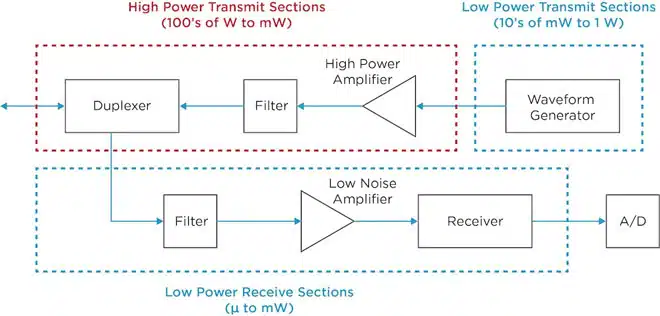
Key functions in radar systems include: 

Duplexing  

A duplexer is tasked with ensuring that transmit and receive signals avoid collisions. T/R waveguide tube devices, circulators, filters and switches can all perform this task in different configurations. For example, in low-power T/R modules, a switch might be the preferred duplexer because they’re small and easy to integrate.  
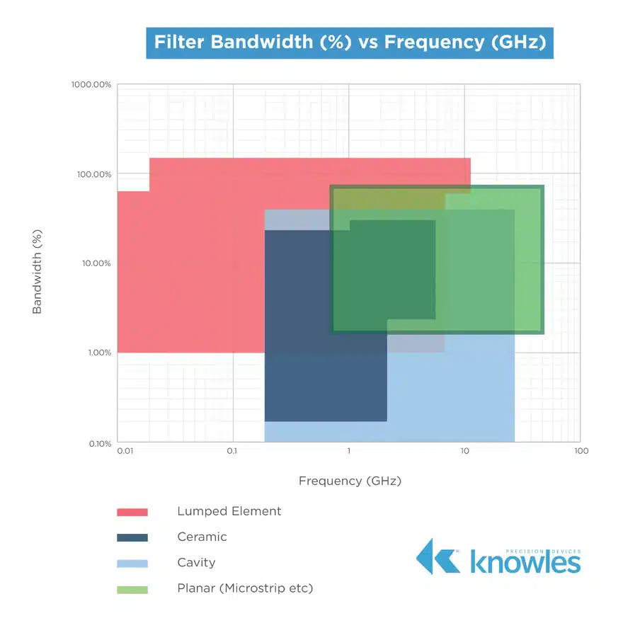
Filtering

Radar systems can leverage filters on both the transmit and receive paths depending on the frequency of operation and filter bandwidth requirements of the system. Filters also play a key role in protecting data converters in direct sampling systems. 

Figure 2: Filter bandwidth vs. frequency; in radar systems, filter selection depends on frequency of operation and bandwidth requirements 
Power Amplification

High-power amplifiers take signals from the waveform generator and increase their signal level to a higher power. Depending on the system, the increase could take the signal from hundreds of watts to megawatts. For example, PAVE PAWS was an early warning radar system and the first all-solid-state active electronically steered array (AESA) system. It had a transmit power of 340W per T/R module. Summed over 1,792 modules, the signal ended up at over 500 kW. High-power amplifiers usually leverage bypass capacitors, pulse storage capacitors and couplers. 

Waveform Generation  

Waveform generators create transmit fairly low-power waveforms. These waveforms are pulsed or otherwise and modulated in frequency or phase as needed. Modern waveform generators are based on digital waveform generation (DWG) and are functionally similar to the arbitrary waveform generators (AWG) commonly found in an RF lab. Here, the desired waveform is expressed mathematically. Through direct digital synthesis (DDS), a digital-to-analog converter (DAC) can produce an analog signal from a digital input. In frequency synthesis, a low-phase noise oscillator with a small form factor is key.

Low Noise Amplification  

Low-noise amplifiers (LNAs) amplify low-amplitude waveforms without decreasing their signal-to-noise ratio (SNR). A strong SNR improves the chances of detecting a target, so LNAs make it possible to detect these hard-to-find targets. Effectiveness is a measure of both resolution and accuracy. Accuracy improves as SNR increases. LNAs rely on bypass capacitors, bias networks, and gain equalizers.  

Receiving    

Receivers are tasked with preparing input frequencies for the analog-to-digital converter (ADC). Depending on the frequencies and sensitivity requirements, one or more down conversion stages may be required. Each stage requires filtering, amplification, and frequency conversion with the help of a low-phase noise frequency source.  

Analog to Digital Conversion     

The goal is to get the signal from the antenna into the analog-to-digital converter (ADC) as directly as possible by removing RF components in its path. When the ADC input matches the RF frequency seen at the antenna, RF sampling and direct sampling become relevant. An RF-ADC’s sampling rate, analog bandwidth, resolution and dynamic range help determine its ability to be used in RF sampling. 

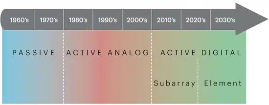
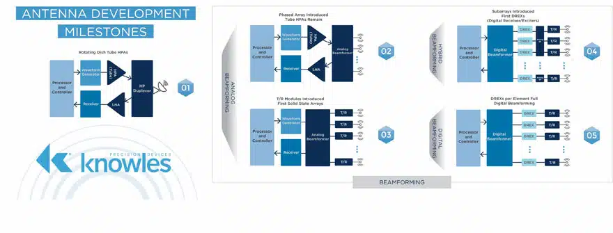
Phased Array Evolution

Radar plays a critical role in defense communications, law enforcement, space exploration, remote sensing and air traffic control. To accommodate different applications, these systems operate in a variety of frequency bands, including L, S, C, X and K bands. With high demand for multi-function, multi-mission systems, options like synthetic-aperture radar (SAR), featuring additional capabilities for imaging and tracking are becoming more popular too.

The most recent transition, shifting the industry from subarray digital phased arrays to element-level digital arrays, demonstrates some key benefits. We’re seeing more flexibility of mode and bandwidth, and when each element in the array has its own ADC, there’s an inherent increase in SNR. 

Figure 3: The technical evolution of radar 

The evolution can be observed in block diagrams too:  

Figure 4: The evolution of radar systems as block diagrams, including passive phased arrays (top left), active phased arrays (top right), subarray digital phased arrays (bottom left) and element-level digital phased arrays (bottom left)

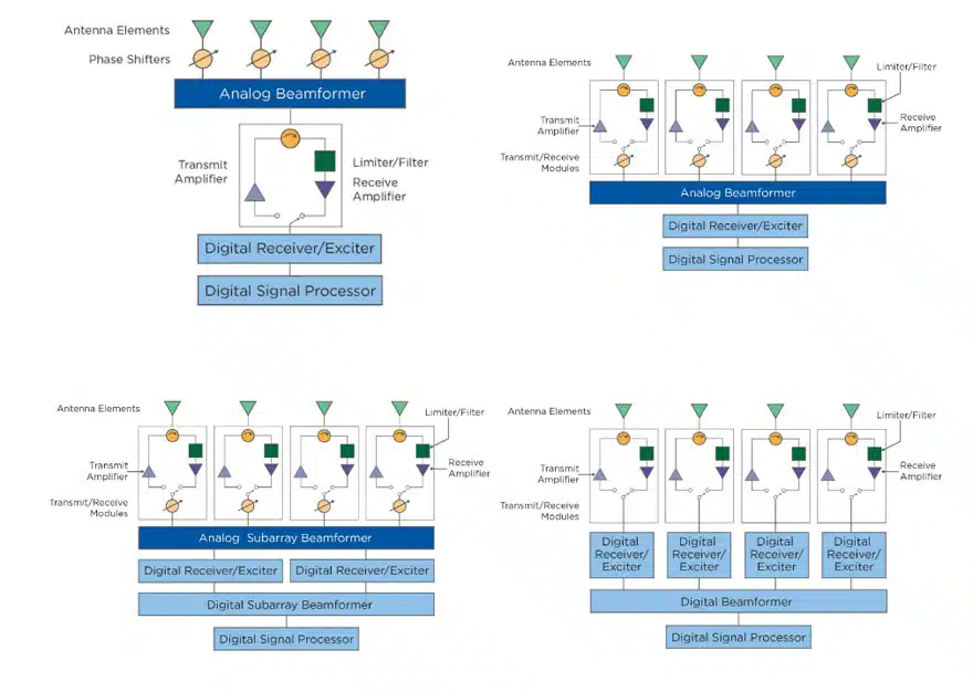
The Expansion of Digital Architecture 

With advancements in adjacent areas like RF and digital electronics, digital arrays are applicable in a wider variety of systems. Considering that these technologies build on each other, a digital-array radar is built on the fundamentals of a phased array antenna; however, in fully digital arrays, transmitted and received energy can be digitized at the element level. Digital-array radar can form multiple receive beams simultaneously. The number of beams, instantaneous bandwidth and dynamic range are only limited by the data converters, digital hardware specifications and power consumption.

As the industry expands on the capabilities of RF-ADCs in terms of analog bandwidth and sampling frequency, every-element DREX circuits are starting to emerge. This places fast converters close to the antenna and encourages the development of high-rejection filters to protect receivers. 

Duplexing

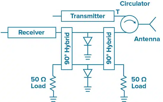
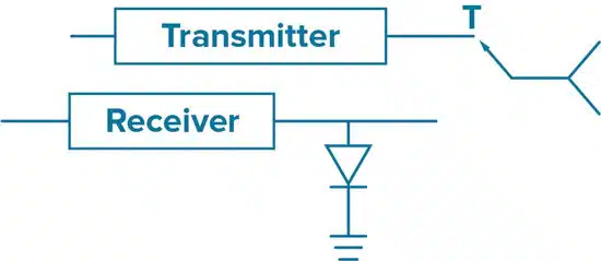
There are two main approaches to duplexing in modern systems. One leverages a circulator and a hybrid coupler. The other uses a single pole double throw switch (SPDT).  

Circulator and Hybrid Coupler Vs. Single Pole Double Throw Switch (SPDT) 

In radar systems with a traditional Tx/Rx antenna, duplexers separate Tx/Rx signals during operation, allowing the antenna to be used for transmitting and receiving signals. This function is particularly important for maintaining performance in high-power radar systems.  

Using a circulator, limiter and an SPDT switch, Tx/Rx signals can be kept separate yet connected to the same antenna.  

In this case, the circulator directs transmit energy to the antenna and isolates the transmitter from input energy. Hybrid couplers and limiters join forces to protect the receiver by directing reflected transmit energy and unwanted input energy to a load for dissipation.  

Thermal design considerations are particularly important for 90° input couplers. Excessive heat caused by power dissipation can destroy these resistors or change their resistance values. If either of these conditions occurs, the mismatched load will reflect power back into the coupler because the resistors won’t be able to terminate limiter reflections. Knowles Precision Devices tests couplers over temperature to avoid this potential pitfall. 

Relying on a SPDT switch and limiter to protect the received signal requires fast, robust power switches. Here, the switch directs energy from the transmitter to the antenna and then to the receiver. The limiter helps protect the receiver. 

Figure 5: Circulator and hybrid coupler duplexing scheme
Figure 6: SPDT duplexing scheme

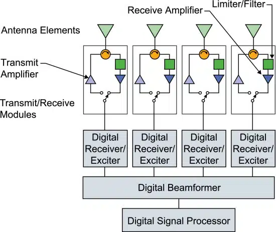
T/R modules are an essential component of active electronically scanned phased arrays (AESA). These modules provide a high-power transmit path and a sensitive receive path to interface directly with a radiating element. Paths either operate using a parallel structure with elements designed to isolate and direct signals, like circulators and limiters, or using a time-multiplexed technique with solid-state switches. 

Figure 7: Milestones in antenna development journey from analog to digital 

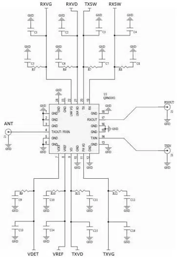
The Evolution of T/R Modules and High-Power GaN RF Switches

T/R modules appeared on the scene in the 1980s. As these modules evolved alongside radar system development, beamforming best practices have too. Today, duplexing is still an important function in a digital beamforming array. 

Figure 8: Duplexing is diagrammed as a circulator and takes place in each T/R module
Figure 9: GaN-based T/R module with a circulator for duplexing (top) vs. upgrading to a switch for duplexing (bottom). Source. 

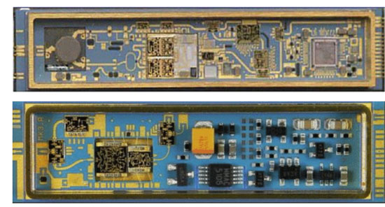
Monolithic microwave integrated circuit (MMIC) devices rely on passive components, like bias networks and decoupling capacitors, to ensure proper operations. The SPDT can be integrated into a single T/R module MMIC, but more passive components are required to support additional functionality. For example, a typical T/R module requires bias and control line networks.   

Figure 6: Monolithic microwave integrated circuit (MMIC) device

Related

Source: Knowles Precision Devices

Recent Posts

2026 Power Magnetics Design Trends: Flyback, DAB and Planar

13.2.2026
30

Mechanical Drift Indicator of Tantalum Capacitor Anodes Degradation under Reverse Bias

3.2.2026
48

Enabling Software‑Defined Vehicle Architectures: Automotive Ethernet and Zonal Smart Power

2.2.2026
42

Calculating Resistance Value of a Flyback RC Snubber 

2.2.2026
59

Bourns Releases High‑Q Air Coil Inductors for RF Aplications

29.1.2026
52

Power Electronics Tools for Passives and Magnetic Designs

3.2.2026
108

Modelithics Releases Component Model Library for SIMULIA CST Studio Suite

27.1.2026
41

DC/DC Push‑Pull Converter vs PSFB Design Guide

12.1.2026
280

Modelithics COMPLETE Library v25.8 for Keysight ADS

7.1.2026
62

Upcoming Events

Feb 24
16:00 - 17:00 CET

Mastering Galvanic Isolation: Ensuring Safety in Power Electronics

Mar 3
16:00 - 17:00 CET

Cybersecurity at the Eleventh Hour – from RED to CRA – Information and Discussion

Mar 21
All day

PSMA Capacitor Workshop 2026

View Calendar

Popular Posts

  • Buck Converter Design and Calculation

    0 shares
    Share 0 Tweet 0
  • Boost Converter Design and Calculation

    0 shares
    Share 0 Tweet 0
  • LLC Resonant Converter Design and Calculation

    0 shares
    Share 0 Tweet 0
  • Flyback Converter Design and Calculation

    0 shares
    Share 0 Tweet 0
  • Ripple Current and its Effects on the Performance of Capacitors

    3 shares
    Share 3 Tweet 0
  • Dual Active Bridge (DAB) Topology

    0 shares
    Share 0 Tweet 0
  • What is a Dielectric Constant and DF of Plastic Materials?

    4 shares
    Share 4 Tweet 0
  • MLCC and Ceramic Capacitors

    0 shares
    Share 0 Tweet 0
  • 3-Phase EMI Filter Design, Simulation, Calculation and Test

    0 shares
    Share 0 Tweet 0
  • MLCC Case Sizes Standards Explained

    0 shares
    Share 0 Tweet 0

Newsletter Subscription


Passive Components Blog

© EPCI - Leading Passive Components Educational and Information Site

  • Home
  • Privacy Policy
  • EPCI Membership & Advertisement
  • About

No Result
View All Result
  • Home
  • Knowledge Blog
  • PCNS

© EPCI - Leading Passive Components Educational and Information Site

This website uses cookies. By continuing to use this website you are giving consent to cookies being used. Visit our Privacy and Cookie Policy.
Go to mobile version