Passive Components Blog
No Result
View All Result
  • Home
  • NewsFilter
    • All
    • Aerospace & Defence
    • Antenna
    • Applications
    • Automotive
    • Capacitors
    • Circuit Protection Devices
    • electro-mechanical news
    • Filters
    • Fuses
    • Inductors
    • Industrial
    • Integrated Passives
    • inter-connect news
    • Market & Supply Chain
    • Market Insights
    • Medical
    • Modelling and Simulation
    • New Materials & Supply
    • New Technologies
    • Non-linear Passives
    • Oscillators
    • Passive Sensors News
    • Resistors
    • RF & Microwave
    • Telecommunication
    • Weekly Digest

    How a Digital Structural Twin Can Predict Tantalum Capacitor Reliability

    SCHURTER Buys Biaodi to Boost High-Voltage Protection Portfolio

    Binder Hybrid Connector Simplifies One Cable Automation

    Tapped Inductor Buck Converter Fundamentals

    TAIYO YUDEN Releases Mini Metal Power Inductors

    Molecular Memristor Shows Record 145 kH Emergent Inductance

    Planar vs Conventional Transformer: When it Make Sense

    Researchers Propose Next‑Gen Compact Memory Using Ultra-thin Ferroelectric Capacitors

    Nichicon ADN Automotive Hybrid Aluminum Capacitors Now Available in EMEA

    Trending Tags

    • Ripple Current
    • RF
    • Leakage Current
    • Tantalum vs Ceramic
    • Snubber
    • Low ESR
    • Feedthrough
    • Derating
    • Dielectric Constant
    • New Products
    • Market Reports
  • VideoFilter
    • All
    • Antenna videos
    • Capacitor videos
    • Circuit Protection Video
    • Filter videos
    • Fuse videos
    • Inductor videos
    • Inter-Connect Video
    • Non-linear passives videos
    • Oscillator videos
    • Passive sensors videos
    • Resistor videos

    Tapped Inductor Buck Converter Fundamentals

    Planar vs Conventional Transformer: When it Make Sense

    Modeling Fringing Field Losses in Inductors & Transformers

    Why Power Inductors Use a Ferrite Core With an Air Gap

    Transformer-Based Power-Line Harvester Magnetic Design

    Thermal Modeling of Magnetics

    Standard vs Planar LLC transformers Comparison for Battery Chargers

    How Modern Tools Model Magnetic Components for Power Electronics

    Advanced Loss Modeling for Planar Magnetics in the Frenetic Planar Tool

    Trending Tags

    • Capacitors explained
    • Inductors explained
    • Resistors explained
    • Filters explained
    • Application Video Guidelines
    • EMC
    • New Products
    • Ripple Current
    • Simulation
    • Tantalum vs Ceramic
  • Knowledge Blog
  • DossiersNew
  • Suppliers
    • Who is Who
  • PCNS
    • PCNS 2025
    • PCNS 2023
    • PCNS 2021
    • PCNS 2019
    • PCNS 2017
  • Events
No Result
View All Result
Passive Components Blog
No Result
View All Result

RF PCB Connector Impedance Matching and Dynamics

1.7.2025
Reading Time: 4 mins read
A A

This Würth Elektronik presentation is about sharing impedance variations and comparative analyses of transmission line structures and connector configurations.

In first segment, there is comparative analysis of PCB transmission line structures: straight, changed shape, and angle lines. In second segment, we investigate the impedance variation of connector contacts to PCB, including different mounting type.

RelatedPosts

Würth Elektronik Introduces Compact Flat-wire SMT Power Inductors for Automotive

Heatsink Design and Thermal Interface Materials for Reliable Electronics

Würth Elektronik Expanded Capacity for Validation and Services in Asia

Strategies for optimizing impedance across transmission lines, connectors, and PCB transmission line contact areas will be the last segment.

Optimizing Impedance Dynamics: Tuning PCB Transmission Lines and Connectors

This presentation explores the critical aspects of impedance matching in PCB transmission lines and connectors. It delves into common challenges, key factors influencing impedance, and provides technical guidelines for achieving optimal impedance dynamics in high-frequency applications.

1. Introduction

Effective impedance matching is essential for maximizing power transfer, minimizing signal reflections, reducing cross-talk, and minimizing energy loss in electronic circuits. This paper outlines practical approaches to addressing impedance mismatches in PCB transmission lines and connectors, with a focus on real-world applications and simulation-supported methodologies.

2. The Importance of Impedance Matching

  • Maximizing Power Transfer: Ensures efficient signal delivery.
  • Minimizing Signal Reflections: Reduces distortions that compromise signal integrity.
  • Reducing Cross-Talk: Essential for maintaining clarity in high-speed circuits.
  • Minimizing Energy Loss: Enhances overall system efficiency.

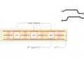
3. Transmission Line Design Considerations

  • Types of Transmission Lines:
    • Coplanar Waveguide with Ground (CPWG): Ideal for extending transmission from connector to signal source.
    • Microstrip Line: Commonly used for connections between connectors and antennas or test boards.
  • Impedance Influencing Factors:
    • Trace width and geometry
    • Angular propagation and path discontinuities
    • Material properties and environmental factors

4. Common Challenges in Impedance Matching

  • Right-Angle Turns: Cause impedance discontinuities leading to signal reflections.
  • Connector Design: Variations in connector types (End Launch, Through-Hole Technology (THT), Surface Mount Technology (SMT)) introduce unique impedance challenges.
  • Gap Dimensions: Gaps between connectors and PCB, and between center contacts and ground planes, critically affect impedance.

5. Technical Guidelines for Optimizing Impedance

  • PCB Trace Adjustments:
    • Implement smooth arcs instead of right angles.
    • Gradually transition trace widths to avoid abrupt changes.
    • Optimize gap distances through simulation.
  • Connector Design Optimization:
    • Adjust internal structures, such as adding notches or modifying air-to-dielectric ratios.
    • Tailor center contact dimensions and placement.
    • Balance the outer and inner contact geometries.

6. Simulation and Testing Methodologies

  • Simulation Tools: Use of HFSS software for advanced modeling.
  • Empirical Testing: Validation through Time Domain Reflectometry (TDR) and Vector Network Analysis (VNA).
  • Iterative Design Process: Combining simulation data with physical prototypes for optimal tuning.

7. Case Studies and Practical Applications

  • Customized Solutions: Documenting instances where tailored connector designs resolved critical impedance issues.
  • High-Frequency Considerations: Specific challenges and solutions for frequencies above 6 GHz.

8. Conclusion

Achieving optimal impedance matching requires a multifaceted approach, combining theoretical knowledge, simulation, and practical testing. By addressing the key factors discussed, electronic designers can significantly enhance signal integrity and system performance.

Related

Source: Würth Elektronik

Recent Posts

Heatsink Design and Thermal Interface Materials for Reliable Electronics

27.4.2026
37

Würth Elektronik Introduces Lead-Free SMT Spacers

11.2.2026
76

Coaxial Connectors and How to Connect with PCB

17.12.2025
591

PCB Manufacturing, Test Methods, Quality and Reliability

17.12.2025
284

Murata Releases World’s First Inner Cavity-Structure Ultra-Low-Loss LCP Flexible Substrate

10.12.2025
130

Connector PCB Design Challenges

3.10.2025
80

Panasonic Industry to Double Production of MEGTRON PCB Materials

15.9.2025
95

Glass Core Technology Breakthrough Potential for High-Speed Interconnects

5.1.2026
230

What Track Width To Use When Routing PCB

6.6.2025
160

Upcoming Events

May 19
16:00 - 17:00 CEST

Designing Qi2 Wireless Power Systems: Practical Development and EMC Optimization

Jun 2
16:00 - 17:00 CEST

Calculation, Simulation and Measurement of 800V EMC Filters

Jun 16
16:00 - 17:00 CEST

EMC with EMC – EMC‑compliant design with electromechanical connectors

View Calendar

Popular Posts

  • Buck Converter Design and Calculation

    0 shares
    Share 0 Tweet 0
  • Boost Converter Design and Calculation

    0 shares
    Share 0 Tweet 0
  • Flyback Converter Design and Calculation

    0 shares
    Share 0 Tweet 0
  • LLC Resonant Converter Design and Calculation

    0 shares
    Share 0 Tweet 0
  • MLCC and Ceramic Capacitors

    0 shares
    Share 0 Tweet 0
  • Dual Active Bridge (DAB) Topology

    0 shares
    Share 0 Tweet 0
  • Capacitor Charging and Discharging

    0 shares
    Share 0 Tweet 0
  • What Electronics Engineer Needs to Know About Passive Low Pass Filters

    0 shares
    Share 0 Tweet 0
  • Ripple Current and its Effects on the Performance of Capacitors

    3 shares
    Share 3 Tweet 0
  • MLCC Case Sizes Standards Explained

    0 shares
    Share 0 Tweet 0

Newsletter Subscription


Passive Components Blog

© EPCI - Leading Passive Components Educational and Information Site

  • Home
  • Privacy Policy
  • EPCI Membership & Advertisement
  • About

No Result
View All Result
  • Home
  • Knowledge Blog
  • PCNS

© EPCI - Leading Passive Components Educational and Information Site

This website uses cookies. By continuing to use this website you are giving consent to cookies being used. Visit our Privacy and Cookie Policy.
Go to mobile version