Passive Components Blog
No Result
View All Result
  • Home
  • NewsFilter
    • All
    • Aerospace & Defence
    • Antenna
    • Applications
    • Automotive
    • Capacitors
    • Circuit Protection Devices
    • electro-mechanical news
    • Filters
    • Fuses
    • Inductors
    • Industrial
    • Integrated Passives
    • inter-connect news
    • Market & Supply Chain
    • Market Insights
    • Medical
    • Modelling and Simulation
    • New Materials & Supply
    • New Technologies
    • Non-linear Passives
    • Oscillators
    • Passive Sensors News
    • Resistors
    • RF & Microwave
    • Telecommunication
    • Weekly Digest

    Designing a Custom Core Transformer for 10 kW LLC Data Center Power Stages

    Magnetics Design in High‑Frequency GaN Converters

    ECIA Industry Pulse April 2026: Sentiment Cools but Stays Strong

    Industrial Passive Components Markets and Technologies 2026

    Automotive Passive Components Technology Dossier

    Samsung Electro-Mechanics Signs 1.5T KRW Silicon Capacitor AI Contract

    Murata Expands Thermistor Production Capacity at Yokaichi Plant

    Hirose Expands Compact High‑Voltage EV connectors

    Qi2 Wireless Charging: Inductors, Capacitors and EMC Filters

    Trending Tags

    • Ripple Current
    • RF
    • Leakage Current
    • Tantalum vs Ceramic
    • Snubber
    • Low ESR
    • Feedthrough
    • Derating
    • Dielectric Constant
    • New Products
    • Market Reports
  • VideoFilter
    • All
    • Antenna videos
    • Capacitor videos
    • Circuit Protection Video
    • Filter videos
    • Fuse videos
    • Inductor videos
    • Inter-Connect Video
    • Non-linear passives videos
    • Oscillator videos
    • Passive sensors videos
    • Resistor videos

    Magnetics Design in High‑Frequency GaN Converters

    Qi2 Wireless Charging: Inductors, Capacitors and EMC Filters

    Two‑capacitor paradox explained for engineers

    Capacitances of Nonlinear MLCCs: What Datasheets Don’t Tell You

    Tapped Inductor Buck Converter Fundamentals

    Planar vs Conventional Transformer: When it Make Sense

    Modeling Fringing Field Losses in Inductors & Transformers

    Why Power Inductors Use a Ferrite Core With an Air Gap

    Transformer-Based Power-Line Harvester Magnetic Design

    Trending Tags

    • Capacitors explained
    • Inductors explained
    • Resistors explained
    • Filters explained
    • Application Video Guidelines
    • EMC
    • New Products
    • Ripple Current
    • Simulation
    • Tantalum vs Ceramic
  • Knowledge Blog
  • DossiersNew
  • Suppliers
    • Who is Who
  • PCNS
    • PCNS 2025
    • PCNS 2023
    • PCNS 2021
    • PCNS 2019
    • PCNS 2017
  • Events
No Result
View All Result
Passive Components Blog
No Result
View All Result

Risk of Tantalum Capacitor Anode Overheating: Modeling and Practical Solutions

18.2.2025
Reading Time: 9 mins read
A A

This article by Dr. V. Azbel, an Independent consultant on tantalum capacitors, introduces software-based approach on assessing the risk of tantalum capacitor anode overheating by modeling and practical solutions example.

Introduction

The development of a tantalum capacitor (TC) anode requires precise control over sintering and forming processes. One of the key challenges is anode overheating during the formation stage, which is associated with the growth of the amorphous tantalum pentoxide (Ta₂O₅) layer and its impact on the thermal conductivity of the anode neck. Traditional methods for calculating anode parameters require significant time and do not allow for an accurate assessment of overheating risks.

RelatedPosts

Using Stress–Strain Curves to Diagnose Tantalum Powders for Capacitors

How a Digital Structural Twin Can Predict Tantalum Capacitor Reliability

Energy Localization in Tantalum Anode Formation: A Structural Perspective

This study proposes a software-based approach to optimizing anode parameters. The developed model quantitatively evaluates the influence of structural characteristics and technological parameters on the anode’s thermal balance. The primary assessment criterion is the Q/Wa coefficient, where Q represents heat dissipation and Wa denotes the energy released. To minimize the risk of overheating, the Q/Wa value must exceed 10.

Modeling Methodology

The modeling of anode thermal balance is based on a geometric representation of its structure. The key stages of the methodology include:

  1. Modeling the Porous Structure of the Anode
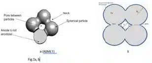
    • The anode represents a set of spherical particles forming pores and necks (see Fig. 1a, b).
    • The geometry of the neck critically affects thermal conductivity and electric current distribution.
Fig. 1a,b
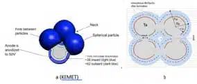
  1. Oxide Layer Formation Process
    • During the formation stage, the amorphous Ta₂O₅ Sooner grows inward and outward from the neck surface (see Fig. 2a, b).
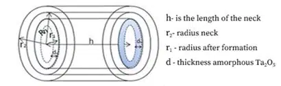
    • The growth of the oxide layer (d) reduces the cross-sectional area of the neck (S = π⋅(Rn)²/4) (see Fig. 3), increasing resistance and the released energy Wa.
    • If the oxide layer reaches a critical thickness, the neck becomes completely blocked, leading to anode failure.
Fig 2a,b
Fig.3
  1. Evaluation of Heat Transfer in the Neck Region
    • The primary mechanisms (see Appendix) include the thermal conductivity of tantalum and the amorphous Ta₂O₅ layer.
    • When the oxide’s thermal conductivity is low, heat accumulates, increasing the likelihood of local overheating.
  2. Determining the Q/Wa Coefficient
    • This coefficient is calculated based on the thermal conductivity, resistance, and neck geometry.
    • Experimental data* confirm that for stable anode operation, Q/Wa > 10.
  3. *Tested using tantalum capacitor anodes that have passed reliability testing.

Influence of Anode Parameters on Overheating Risk

Factors affecting heat distribution and the likelihood of overheating include:

  • Neck size and anode porosity: A smaller neck cross-sectional area increases the surface area (see Fig. 4). However, this also increases electrical resistance and the risk of localized heating.
  • Anode Thickness and Shape: Complex geometry complicates heat dissipation, creating localized overheating zones.
  • Transition Layer Between Ta and Ta₂O₅: Reduces thermal conductivity and increases resistance.
Fig.4 Surface Area and Inter-particles Sinter Neck Size as a function of Sinter Temperature

Advantages of the Software-Based Approach

The developed software allows for:

  • Automatic optimization of anode parameters.
  • Prediction of overheating risk based on Q/Wa.
  • Reduction in the number of experiments and time required for developing new TC designs.
  • Elimination of subjective errors in design.

Conclusions

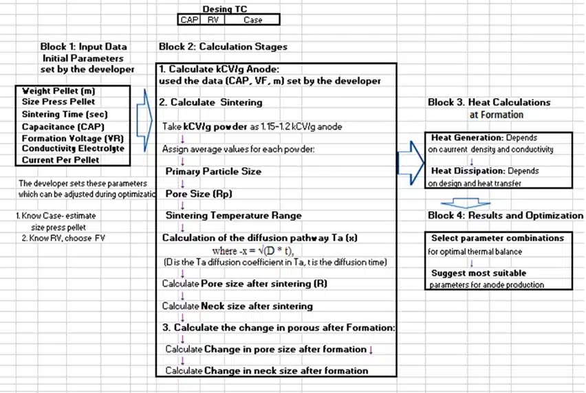
Modeling the anode’s thermal balance, considering neck structure and the oxide layer formation mechanism significantly improves the accuracy of overheating risk predictions. The developed software (with a calculation algorithm flowchart presented in Table 1, see Appendix) provides a convenient tool for the automated selection of optimal anode parameters, enhancing reliability and reducing failure probability. Future model improvements may include accounting for the mechanical properties of the anode for a more detailed analysis.

Integration of the Software into the Anode Production Process

The developed software is designed to calculate the hypothetical risk of overheating, serving as a key tool for optimizing anode parameters. Based on this foundation, an advanced version has been created, enabling real-time detection of issues within the ongoing production process. 

The new software version incorporates real-time integration of experimental data, further increasing the accuracy of overheating risk predictions. This functionality allows for continuous monitoring and adaptive adjustments, ensuring stable process parameters and minimizing failure risks.

Appendix

The table below clearly illustrates the dependence of BET, capacitance, and forming voltage on the size of primary powder particles.

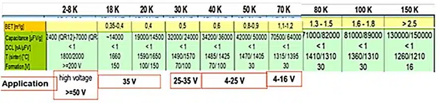
BET determines the range of powder applications—from high-voltage to low-voltage capacitors.
The primary influencing factor is the size of the primary particles while modifying the pressing density and sintering temperature further adjusts the properties.
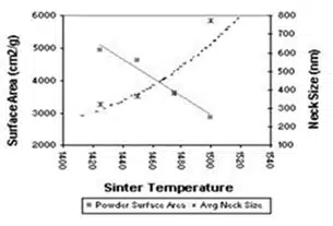
Sintering regulates porosity (capacitance) and the neck size between grains (forming voltage), allowing the material to be tailored to the required parameters.

This information was used to develop the program flowchart below, which enables the selection of optimal powder parameters based on specified capacitance and operating voltage requirements.

Table 1 Calculation algorithm flowchart 

Experimental data (CABOT, H.C. Starck) used in program development. Size prime particles powder- CABOT

Examples of the program’s operation

Table 2 presents data on the influence of the anode mass within a single design on the risk ofoverheating.

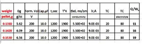
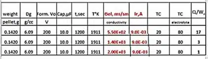
Table 3 shows the influence of different electrolysis parameters applied to a single-sintered pellet design on the risk of anode overheating.

Heat Transfer and Energy Dissipation Mechanisms in the Neck Region, used in Software

The main mechanisms include:

  1. Heat Transfer Through the Cross-Sectional Area of the Neck (q):

q = k⋅S⋅ΔT/h, where k is the thermal conductivity of tantalum (0.4 W·m⁻¹·K⁻¹), ΔT is the temperature difference, which can reach 450°C at the onset of amorphous film crystallization.

  1. Heat Transfer Through the Surface of the Amorphous Film (Q):

Q = k1⋅A⋅ΔT/d, where k₁ is the thermal conductivity of the amorphous film (0.7 W·m⁻¹·K⁻¹), A is the surface area of the film, and d is its thickness.

  1. Energy Dissipation in the Neck
    The reduction of the neck’s cross-sectional area due to increasing forming voltage raises electrical resistance, leading to an increase in dissipated energy (Wa). According to the proposed model, this energy is calculated as:

Wa = Ir²⋅ρ⋅h/S, where Ir is the forming current, ρ is the resistivity, h is the neck length, and S is the cross-sectional area:

S = π⋅L²/4, where L=Rn ​(see Fig. 3).

  1. Risk of Complete Neck Blockage
    If the forming voltage exceeds the optimal level, the radius of the oxide layer (r₁) becomes equal to the radius of the tantalum core (Rn). This results in complete neck blockage, a reduction in capacitance, and an increased risk of failure.

Related

Source: Vladimir Azbel

Recent Posts

Designing a Custom Core Transformer for 10 kW LLC Data Center Power Stages

22.5.2026
25

Magnetics Design in High‑Frequency GaN Converters

22.5.2026
27

Industrial Passive Components Markets and Technologies 2026

21.5.2026
68

Automotive Passive Components Technology Dossier

21.5.2026
49

Samsung Electro-Mechanics Signs 1.5T KRW Silicon Capacitor AI Contract

21.5.2026
45

Qi2 Wireless Charging: Inductors, Capacitors and EMC Filters

21.5.2026
23

Samsung Introduced Low ESL 3-Terminal Reverse-Geometry MLCCs for High-Performance ADAS

20.5.2026
47

Using Stress–Strain Curves to Diagnose Tantalum Powders for Capacitors

20.5.2026
27

Samsung Launches Ultra-Compact 008004 High Q MLCC for Next-Generation RF Applications

20.5.2026
32

Upcoming Events

Jun 2
16:00 - 17:00 CEST

Calculation, Simulation and Measurement of 800V EMC Filters

Jun 16
16:00 - 17:00 CEST

EMC with EMC – EMC‑compliant design with electromechanical connectors

View Calendar

Popular Posts

  • Buck Converter Design and Calculation

    0 shares
    Share 0 Tweet 0
  • Boost Converter Design and Calculation

    0 shares
    Share 0 Tweet 0
  • Flyback Converter Design and Calculation

    0 shares
    Share 0 Tweet 0
  • LLC Resonant Converter Design and Calculation

    0 shares
    Share 0 Tweet 0
  • MLCC and Ceramic Capacitors

    0 shares
    Share 0 Tweet 0
  • What Electronics Engineer Needs to Know About Passive Low Pass Filters

    0 shares
    Share 0 Tweet 0
  • Capacitor Charging and Discharging

    0 shares
    Share 0 Tweet 0
  • Dual Active Bridge (DAB) Topology

    0 shares
    Share 0 Tweet 0
  • Ripple Current and its Effects on the Performance of Capacitors

    3 shares
    Share 3 Tweet 0
  • Samsung Electro-Mechanics Releases High-Capacitance MLCCs for AI Server Applications

    0 shares
    Share 0 Tweet 0

Newsletter Subscription


Passive Components Blog

© EPCI - Leading Passive Components Educational and Information Site

  • Home
  • Privacy Policy
  • EPCI Membership & Advertisement
  • About

No Result
View All Result
  • Home
  • Knowledge Blog
  • Dossiers
  • PCNS

© EPCI - Leading Passive Components Educational and Information Site

This website uses cookies. By continuing to use this website you are giving consent to cookies being used. Visit our Privacy and Cookie Policy.
Go to mobile version