




Linear and switching regulators solve different power-supply problems: linear regulators offer simple regulation without an intentional switching power stage, while switching regulators usually reduce conversion losses when the input-to-output voltage difference or load current is substantial.
This article compares their operating principles, efficiency, thermal behavior, noise and passive-component requirements for design engineers selecting board-level DC power supplies.
Key Takeaways
The choice depends on the complete operating envelope, not on a single efficiency or noise specification.
- A linear regulator is often appropriate for a small voltage reduction, modest dissipation or a sensitive analog supply, provided its dropout, noise and stability requirements are met.
- A switching regulator can step voltage down, up or between ranges, depending on topology, and usually offers a thermal advantage when a linear regulator would dissipate excessive power.
- Linear-regulator efficiency depends mainly on the output-to-input voltage ratio and operating current. Switching-regulator efficiency must be checked across input voltage, load and operating mode.
- Capacitance, ESR, ripple-current capability, inductor saturation and PCB layout are functional design parameters, not secondary implementation details.
- A switching preregulator followed by an LDO can combine efficient voltage reduction with additional ripple attenuation, but only if adequate headroom and frequency-dependent rejection are maintained.
- Validate load transients, startup, temperature and EMI on the actual assembly. Neither regulator category guarantees the required dynamic or noise performance by itself.
Power Regulation Essentials
A voltage regulator maintains the supply delivered to a load despite changes in input voltage and load current, within its specified operating limits. The implementation affects energy loss, temperature rise, supply noise and the behavior of the surrounding circuit. [1]
This comparison focuses on board-level DC voltage regulation, especially nonisolated point-of-load supplies. Isolated switching converters are included where transformers and safety requirements affect selection, but isolation-system design and mains front ends require additional application-specific analysis.
Passive components support different functions: capacitors provide local energy storage and filtering, inductors control energy transfer in magnetic switching converters, resistors establish feedback or sensing functions, and transformers transfer energy across circuits where the topology requires them. These functions should not be treated as interchangeable.
Key Performance Parameters
- Output accuracy: the permitted deviation from nominal voltage, including reference accuracy, feedback-component tolerance and operating conditions.
- Load regulation: the steady-state output-voltage change caused by a specified change in load current.
- Line regulation: the steady-state output-voltage change caused by a specified change in input voltage.
- Efficiency: output power divided by input power at a defined operating point. For battery systems, the time spent in active, idle and shutdown states also matters.
- Transient response: output undershoot, overshoot and settling following a specified input or load change. Compare the load-step amplitude, slew rate, capacitance and measurement conditions.
- Thermal dissipation: losses in the regulator and associated components, evaluated against their temperature limits and the actual heat-removal path.
- Noise performance: intrinsic output noise, periodic ripple, switching spikes and conducted or radiated interference, each evaluated over the relevant frequency range.
- Operating envelope: input and output ranges, dropout or duty-cycle limits, current capability, startup behavior and protection functions. [1–3]
Linear Regulators: Simplicity and Clean Output
A linear regulator controls a series pass element continuously rather than deliberately switching its power path on and off. It can provide a compact supply with low switching-related disturbance, but its usable current depends on both electrical limits and heat dissipation. [1]
Operating Principle
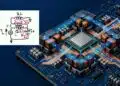
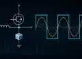
An error amplifier compares a representation of the output voltage with a reference and adjusts a bipolar transistor or MOSFET pass element. The regulator absorbs the input-to-output voltage difference across that element. Figures 1 and 2 retain the original principle illustration and circuit example.


For a conventional positive series regulator, the input must remain above the output by at least the required dropout voltage. Low-dropout regulators, or LDOs, reduce this minimum difference; they do not remove the underlying dissipation associated with a given input voltage, output voltage and load current. Check dropout at the required current and temperature, not only at a typical headline condition. [1]
Efficiency and Dissipation
Let VIN and VOUT be the input and output voltages, IOUT the load current, and IG the current returned through the regulator ground connection at the operating point. For a conventional single-input series regulator, its approximate internal loss PLOSS is given by Eq. (1). External feedback-divider losses or separate bias supplies must be added where applicable. [1, 2]
Under the same assumptions, efficiency η follows Eq. (2). The approximation on the right applies when ground current is small compared with load current. Datasheet no-load quiescent current is not necessarily identical to ground current under every load condition. [1, 2]
Eq. (1) shows why a large voltage drop at substantial current creates a thermal problem. Eq. (2) also shows why describing all linear regulators as inefficient is misleading: the voltage-ratio efficiency can be high when the input is only slightly above the output. At very light loads, operating current can become a major part of the power budget. [1, 2]
Advantages
- Few external components and no external power inductor for ordinary series regulation.
- No intentional switching-frequency power-stage ripple, making suitable devices useful for sensitive analog, measurement and RF supplies.
- Potentially fast load-transient response, depending on loop design, load conditions and output capacitance.
- Useful local post-regulation after a switching converter when the LDO has adequate headroom and rejection at the relevant disturbance frequencies. [1, 3]
Limitations
- A conventional positive series regulator only steps voltage down; it cannot boost a positive input or provide galvanic isolation.
- Voltage drop and load current produce heat, which can limit usable current before the nominal current rating is reached.
- Cooling may require additional PCB copper, thermal vias, a suitable package or a heatsink, depending on dissipation and construction.
- Output-capacitor requirements and input-to-output headroom must be respected. Low intrinsic noise does not guarantee strong rejection of upstream ripple at every frequency. [1, 3, 4]
Typical Applications
Suitable applications include operational amplifiers, ADCs, DACs, RF front ends and local post-regulation after DC-DC conversion. A linear regulator can also be appropriate for a low-power auxiliary or standby rail, provided its operating current and dropout behavior suit the complete load profile. These application labels do not replace a noise and thermal budget. [1, 2]
Switching Regulators: Efficiency and Scalability
A switching regulator transfers energy by repeatedly changing the state of its power switches. Magnetic switching converters use inductors or transformers together with capacitors to deliver a regulated output while limiting the losses that would occur in a continuously dissipative pass element. [1]
Operating Principle
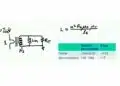
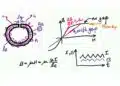
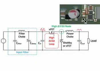
A buck converter steps voltage down; a boost converter steps it up; and suitable buck-boost arrangements regulate across input voltages above or below the desired output. A flyback uses a coupled magnetic component and can provide isolation when designed for that purpose. Figures 3 and 4 retain the original switching-regulator principle illustration and buck circuit example. [1]


For an ideal buck converter operating in continuous conduction, the duty ratio D is related to input and output voltage by Eq. (3). Here tON is the high-side switch on-time and TS is the switching period. Losses, minimum on-time, maximum duty ratio and operating-mode transitions limit the accuracy and applicability of this ideal relationship. [1]
The separate guide to buck converter design and calculation develops the power-stage relationships beyond this architecture comparison.
Control Modes and Integration
Pulse-width modulation, or PWM, is common, but switching regulators are not limited to PWM. Depending on the device, pulse-frequency modulation, pulse skipping, hysteretic control or constant-on-time control may be used. Light-load modes can reduce switching activity and improve efficiency, while changing the ripple spectrum and transient behavior. [5]
Compare forced continuous operation and power-saving modes under the actual load profile. A fixed-frequency operating mode can simplify the placement of switching-related spectral components, but it does not by itself guarantee acceptable noise or EMI. [5]
A controller with external switches offers component-selection flexibility. A monolithic regulator integrates power switches, while a power module can also integrate magnetics and other components. Integrated compensation and modules can reduce design effort, but their permitted external capacitance, thermal conditions and layout requirements still apply. [1, 5]
Advantages
- Usually lower conversion loss than linear regulation when the required voltage reduction and load would otherwise cause substantial dissipation.
- Topology choices for step-down, step-up, inverting, buck-boost and isolated conversion.
- Potentially smaller cooling requirements and higher power density, subject to switching, magnetic and conduction losses.
- Options for synchronous rectification, multiphase operation and current sharing in appropriate high-current systems. [1, 5]
Limitations
- Switching edges and pulsating currents create ripple and potential conducted or radiated interference.
- Power-stage components, current paths and feedback routing require careful selection and layout.
- Loop stability must be maintained with the chosen inductance, effective capacitance and ESR. Some devices need external compensation; others provide internal compensation within specified limits.
- Efficiency varies with input voltage, load, frequency and mode. Switching and control-circuit losses can be important at light load.
- Transient performance depends on control architecture, available inductor-current slew rate and output capacitance; it is not universally slower than linear regulation. [1, 5]
Typical Applications
Switching regulators serve portable electronics, laptops, smartphones, industrial controls, telecom equipment and high-current digital loads. Switching conversion also underpins renewable-energy and larger power-conversion systems, although their semiconductor, magnetic, insulation and protection requirements extend beyond ordinary board-level point-of-load design. [1]
Thermal Management and Efficiency vs Noise
Efficiency, temperature and noise must be assessed together. A supply that meets its nominal voltage specification can still fail the application through excessive junction temperature, load-step excursions or interference coupled into a sensitive signal path.
Thermal Assessment
For a linear regulator, calculate dissipation with Eq. (1) at the relevant combinations of input voltage and load. For a switching converter, account for losses in switches, rectifiers, inductors, capacitors and control circuitry. Lower total loss does not eliminate local hot spots. [1]
The allowable operating current depends on package construction, PCB copper, thermal connections, airflow and enclosure conditions. A datasheet current rating is not a guarantee that the device can continuously deliver that current at any voltage drop or ambient temperature. Thermal shutdown is a protective function, not a normal temperature-control strategy.
Ripple, Intrinsic Noise and PSRR
Intrinsic output noise originates within the regulator. Power-supply rejection ratio, or PSRR, describes attenuation of a small input disturbance reaching the output. These are different specifications: a regulator with low internally generated noise can still pass significant upstream ripple at frequencies where its rejection is poor. [3]
For input and output ripple amplitudes vr,in and vr,out at the same frequency, Eq. (4) defines PSRR in decibels. Compare measurements under matching load, headroom, output-voltage and capacitor conditions. [3]
For an LDO following a switching converter, check PSRR at the switching frequency and relevant disturbance frequencies rather than relying on a low-frequency headline value. Insufficient input-to-output headroom can reduce rejection before the rail completely loses regulation. Output capacitance and PCB parasitics also influence the result. [3]
EMI Control and Measurement
Place the switching converter’s high-frequency input capacitor close to its power-current loop, keep the switch-node area controlled, and separate sensitive feedback and signal paths from noisy power nodes. Filtering and shielding are application-dependent measures; they do not compensate for an unsuitable power layout. [1]
Measure ripple and transients at the intended load connection, using a probe connection and measurement bandwidth appropriate to the specification. Record the setup so that switching spikes, broadband noise and load-step excursions are not compared as though they were the same quantity. A clean local voltage measurement also does not establish system-level EMI compliance.
Cost and Component Count
A simple linear regulator often minimizes initial component count, whereas a switching solution can reduce cooling needs and operating losses. Compare the complete implementation rather than only the regulator IC price. [1, 2]
Include input and output capacitors, magnetics, feedback and compensation components, PCB area, cooling hardware, assembly and validation effort. A power module may cost more as a purchased component while reducing development effort and implementation risk. Conversely, a low-current rail with a small voltage drop may gain little from a more complex switching solution. [1]
For battery-powered equipment, evaluate energy consumption across active, idle and shutdown states. Low operating current, shutdown leakage and the usable battery-voltage range can matter more than peak conversion efficiency at a load the product rarely reaches. [2, 5]
Passive Components in Power Conversion
Passive components determine much of a regulator’s stability, ripple, transient response and thermal performance. Selection must use operating-condition data, not nominal capacitance or inductance alone. [1, 4]
Capacitors
For linear regulation, follow the specific device’s requirements for input and output capacitance, capacitor placement and permissible ESR. Do not assume that replacing an older capacitor with a lower-ESR ceramic part is automatically beneficial: the output network participates in the regulator’s dynamic behavior.
Use effective capacitance after the relevant DC-bias, temperature, tolerance and aging effects. This is particularly important for Class II ceramic capacitors, whose available capacitance under bias can differ substantially from the nominal marking. The component-level introduction to capacitor operation and characteristics provides the underlying terminology. [4]
For a buck converter, the input capacitor carries pulsating current and must have suitable RMS ripple-current capability. Output capacitors affect both ripple and load-transient performance. Compare capacitance, ESR, impedance, voltage rating, ripple-current heating and lifetime under the intended conditions; changing capacitor technology can require a new stability assessment. [1]
Inductors and Transformers
Select a power inductor using inductance under DC bias, peak current, RMS current, winding resistance, core loss and temperature rise. Saturation-current and heating-current ratings describe different limits and may use different manufacturer criteria. Check both against the converter’s ripple and fault behavior. [1]
The basic guide to inductor operation explains energy storage; a regulator design additionally needs the actual part’s current-dependent and frequency-dependent characteristics.
Not every switching regulator uses a transformer. Where a transformer or coupled magnetic component is required, consider turns ratio, magnetizing and leakage inductance, winding losses, insulation and parasitic coupling. In a flyback, energy storage is an intended function of the magnetic component. For broader construction context, see transformer and solenoid functionality. [1]
Resistors and Filter Networks
Feedback resistors contribute to output setting and accuracy; current-sense resistors introduce loss and affect sensing performance. Evaluate tolerance, temperature behavior, power dissipation and placement for the actual function rather than choosing by resistance alone. The introduction to resistor characteristics covers the component basics.
Additional input or output filtering must be checked together with the regulator. A filter changes the impedance seen by the converter or load; adding components without considering damping and loop behavior can worsen transient response or stability. Validate the assembled network over the operating range.
Design and Selection Checklist for Linear and Switching Regulators
Translate the system requirements into a comparison sheet before selecting the regulator and passives. Use guaranteed limits where necessary, and retain the test conditions associated with every typical curve.
- Supply range: record normal input variation, startup conditions, interruptions and expected transients. Separate recommended operating limits from absolute maximum ratings.
- Load profile: specify continuous current, peak current, sleep current, pulse duration and permitted voltage excursions. Include the required startup and shutdown sequence.
- Linear-regulator parameters: compare dropout at load and temperature, ground current, output accuracy, noise bandwidth, PSRR versus frequency, current limiting and required output-capacitor characteristics.
- Switching-regulator parameters: compare topology, input and output range, minimum on-time, duty-cycle limits, current-limit definition, operating frequency, light-load mode, efficiency curves and compensation requirements.
- Passive-component limits: verify effective capacitance, ESR and ripple heating; inductor saturation, heating and losses; and feedback or sense-resistor accuracy and dissipation.
- Catalog versus custom: prefer a catalog part when its documented envelope meets the design. Consider custom magnetics only when geometry, insulation, winding arrangement or another requirement justifies the additional development and qualification work.
- Qualification and sourcing: confirm the exact ordering code, temperature grade, required qualification evidence, traceability and lifecycle status. A mechanically compatible substitute still needs an electrical and thermal equivalence review.
- Safety and protection: define isolation, fault handling, reverse-current behavior and applicable end-equipment requirements. A transformer alone does not establish a compliant isolation barrier, and a protection feature does not replace system-level fault analysis.
- Prototype validation: test line and load regulation, startup, shutdown, load steps, short-circuit behavior, temperature and EMI in the intended assembly. Repeat critical checks after changing passives or layout. [1–5]
Comparative Summary Table
Table 1 summarizes the practical trade-offs for conventional series linear regulators and magnetic switching converters. Each entry depends on the selected device and operating conditions; it is not a substitute for datasheet review or measurement. [1–5]
| Criterion | Linear Regulator | Switching Regulator |
|---|---|---|
| Conversion function | Conventional positive series regulation steps voltage down | Step-down, step-up, buck-boost, inverting or isolated conversion, depending on topology |
| Efficiency | Mainly determined by voltage ratio and ground current; can be high with a small voltage drop | Usually advantageous for substantial conversion ratios or power; varies with load, frequency and mode |
| Noise and EMI | No intentional power-stage switching ripple; intrinsic noise and input-ripple feedthrough remain | Switching ripple and edges require layout and filtering appropriate to the application |
| Complexity | Usually few external components; capacitor requirements still matter | Power stage and loop need attention; integration can reduce external component count |
| Thermal dissipation | Voltage drop multiplied by load current is the main loss term | Loss is distributed among switches, magnetics, capacitors and control circuitry |
| Transient response | Device, headroom, capacitance and load-step conditions determine performance | Control architecture, inductor slew rate and capacitance determine performance |
| Best use case | Small voltage drops, simple auxiliary rails and suitable low-noise analog or RF supplies | Efficiency-critical conversion, higher-power rails and voltage conversion unavailable from a series regulator |
Conclusion
The right regulator balances voltage-conversion requirements, loss, noise, thermal constraints and implementation effort. Start with the input range and load profile, then check the regulator and passive components as one system.
Choose a linear regulator when its dropout and dissipation are acceptable and its simplicity or noise performance benefits the application. Choose a switching regulator when the required conversion function or loss budget makes linear regulation unsuitable. A switching preregulator followed by an LDO can be a useful combination, provided the remaining headroom, rejection spectrum and total losses are verified.
Neither architecture removes the need for capacitor stability checks, current and temperature margins, careful layout and validation on the finished assembly.
FAQ
These answers summarize the selection principles developed above for board-level voltage regulation.
A linear regulator continuously controls a series pass element and dissipates the input-to-output voltage difference at the load current. A switching regulator transfers energy through repeated switching and an associated power stage. The switching topology determines whether it can step voltage down, step it up, invert it or provide isolation.
Use a linear regulator when the available input remains above the required output by sufficient headroom, the calculated dissipation is acceptable and its simplicity or noise performance benefits the load. Typical candidates include sensitive analog rails and local post-regulation. Check dropout, ground current, output-capacitor requirements and frequency-dependent ripple rejection before making the choice.
Switching regulators usually reduce losses when a linear regulator would have to absorb a large voltage drop at substantial current. Suitable topologies also provide boost, buck-boost, inverting or isolated conversion. Their practical advantages depend on efficiency across the actual input and load range, together with magnetic losses, thermal performance, control mode and layout.
Usable current is limited by the device’s electrical ratings, current limiting, dropout and temperature. The main dissipation term is the input-to-output voltage difference multiplied by load current. A nominal current rating does not guarantee continuous operation at every voltage drop. Check the package, PCB heat path, ambient conditions and required output-capacitor network.
No. Switching regulators require careful control of current loops, switch-node geometry and feedback routing, but shielding is an application-dependent measure. Transient response depends on control architecture, operating point, inductance and output capacitance. Compare measured undershoot, overshoot and settling under equivalent load-step conditions rather than assuming that every switching regulator is slower than a linear regulator.
A linear regulator often has a lower initial component count, but cooling and wasted energy can change the total cost. A switching solution adds power-stage and validation requirements while potentially reducing losses and cooling needs. Compare the complete assembly, development effort and operating profile. Integrated modules can reduce implementation effort even when their purchase price is higher.
For capacitors, check effective capacitance, permissible ESR, voltage rating, ripple-current heating and placement. For power inductors, check inductance under bias, peak and RMS current, saturation, winding resistance and core loss. Feedback and sense resistors also affect accuracy and dissipation. Component substitutions require a new assessment of stability, transient response and temperature.
Higher efficiency reduces loss but does not eliminate it. A switching converter dissipates power in semiconductors, magnetics, capacitors and control circuitry, and local hot spots can remain significant. Evaluate the actual PCB, airflow and enclosure. A linear regulator requires the same system-level approach, with particular attention to voltage drop multiplied by load current.
How to Choose Between Switching and Linear Power Regulators
Use this procedure to narrow the architecture choice, then validate the selected regulator and passives together.
Select and validate a regulator architecture for a board-level DC supply.
- Evaluate the application requirements
Define output accuracy, line and load regulation, startup behavior, permitted voltage excursions and the complete active, idle and shutdown load profile.
- Assess input and output voltages
Check the full input range against the required output. Verify linear-regulator dropout or switching-regulator duty-cycle and timing limits at the required current and temperature.
- Define noise and EMI requirements
Separate intrinsic noise, input-ripple rejection, switching ripple and system EMI. For an LDO after a switching converter, compare rejection at the relevant frequencies and available headroom.
- Analyze current and power
Calculate linear-regulator loss and compare switching-converter efficiency across the actual load range. Include operating current and light-load modes rather than relying on peak efficiency.
- Evaluate thermal management
Check semiconductor and passive-component temperatures in the intended PCB, airflow and enclosure. Confirm that the heat-removal path supports continuous operation without relying on thermal shutdown.
- Compare implementation cost
Include passives, PCB area, cooling, assembly and validation effort. Compare controller, monolithic regulator and module options where relevant, and justify any custom magnetics.
- Select and qualify passive components
Verify effective capacitance, ESR, ripple heating, inductor current limits and losses. Confirm exact ordering codes, required qualification evidence, sourcing constraints and insulation requirements where applicable.
- Verify dynamic performance
Test startup, shutdown, line changes and load steps with the selected passives and layout. Record undershoot, overshoot, settling and the measurement conditions, and investigate instability or excessive ringing.
- Make and document the final decision
Choose the architecture that meets electrical, noise, thermal, safety and cost requirements across the operating envelope. Document validation results and the checks required after component or layout changes.
Further Reading
These related guides develop the component-selection and topology topics introduced above.
- Selection of Storage Inductors for DC/DC Converters — a focused continuation for selecting the magnetic energy-storage component.
- Input Filters for DC/DC Converters — further guidance on the converter’s input-filter network.
- SEPIC Converter Design and Calculation — a topology-specific continuation for input ranges crossing the desired output voltage.
- Boost Converter Design and Calculation — further treatment of step-up conversion.
- Flyback Converter Design and Calculation — a continuation for flyback power-stage design.
- Fly-Buck Converter Explained and Comparison to Flyback — context for choosing between related magnetic conversion approaches.
- LLC Resonant Converter Design and Calculation — an extension beyond the board-level regulator comparison into resonant conversion.
- How to Calculate the Output Capacitor for a Switching Power Supply — further development of output-capacitor sizing.
References
The following manufacturer technical publications support the operating principles and selection considerations cited in the article.
- Analog Devices, AN-140: Basic Concepts of Linear Regulator and Switching Mode Power Supplies, Analog Devices, publication year not stated on the accessed HTML version.
- Analog Devices, Linear Regulators in Portable Applications, Analog Devices, 2002.
- John C. Teel, Understanding Power Supply Ripple Rejection in Linear Regulators, Texas Instruments, Analog Applications Journal, second quarter 2005.
- Wilson Fwu, LDO Basics: Capacitor vs. Capacitance, Texas Instruments, SSZT654, 2018.
- Analog Devices, Choose the Right Regulator for the Job: Part 1, Regulator Control Schemes, Analog Devices, 2016.